CN202837643U - Anti-wire jumping and wire clamping optical cable linear tackle - Google Patents
Anti-wire jumping and wire clamping optical cable linear tackle Download PDFInfo
- Publication number
- CN202837643U CN202837643U CN 201220574598 CN201220574598U CN202837643U CN 202837643 U CN202837643 U CN 202837643U CN 201220574598 CN201220574598 CN 201220574598 CN 201220574598 U CN201220574598 U CN 201220574598U CN 202837643 U CN202837643 U CN 202837643U
- Authority
- CN
- China
- Prior art keywords
- pulley
- optical cable
- wire
- jumping
- cable linear
- Prior art date
- Legal status (The legal status is an assumption and is not a legal conclusion. Google has not performed a legal analysis and makes no representation as to the accuracy of the status listed.)
- Expired - Fee Related
Links
Images

Landscapes
- Light Guides In General And Applications Therefor (AREA)
Abstract
本实用新型属于光缆直线滑车技术领域,公开了一种防跳线、卡线光缆直线滑车。其主要技术特征为:包括上端带有挂钩的滑轮架和带有第一线槽的第一滑轮,在所述第一滑轮上方的滑轮架上设置有第二滑轮,在所述第二滑轮中部设置有第二线槽,在进行放紧线、张力放线时,当两边杆塔高,中间杆塔低时,牵引绳、光缆也不会离开滑车的第一线槽和第二线槽,有效地防止跳线和卡线现象的发生,避免了因跳线和卡线造成的安全事故,工作效率大大提高。
The utility model belongs to the technical field of optical cable linear pulleys, and discloses an optical cable linear pulley for preventing wire jumping and jamming. Its main technical features are: it includes a pulley frame with a hook on the upper end and a first pulley with a first wire groove, a second pulley is arranged on the pulley frame above the first pulley, and a second pulley is located in the middle of the second pulley. There is a second wire slot. When the wires are tensioned or tensioned, when the pole towers on both sides are high and the middle tower is low, the traction rope and optical cable will not leave the first wire slot and the second wire slot of the pulley, effectively preventing jumping The phenomenon of line and line jamming avoids safety accidents caused by jumping lines and line jamming, and the work efficiency is greatly improved.
Description
技术领域 technical field
本实用新型属于光缆直线滑车技术领域,具体的讲涉及防跳线、卡线光缆直线滑车。 The utility model belongs to the technical field of optical cable linear pulleys, in particular to an optical cable linear pulley for preventing wire jumping and jamming.
背景技术 Background technique
光缆直线滑车是应用于光缆放紧线施工中的必备工具,目前使用的光缆直线滑车由于结构的原因,存在以下缺陷:其一,在展放光缆施工中,当两边杆塔高,中间杆塔低时,牵引绳、光缆就会离开滑车的滑轮槽,造成跳线现象;当牵引绳、光缆落下时,由于风摆晃动就会偏离牵引方向,落不到滑车槽内就会发生卡槽,这样会造成牵引绳断股,光缆光纤卡断,严重的还会发生牵引绳断开造成人员抽伤、触电、杆塔垮塌等危险事故;其二,光缆与光缆牵引绳在展放过程中会因高差、大风等条件影响,造成光缆与光缆牵引绳从滑车内脱槽跳线或卡线等危险因素。光缆与光缆牵引绳在光缆直线滑车内安全通过决定了施工安全与施工质量。 The optical cable linear block is an essential tool used in the construction of the optical cable tensioning line. Due to structural reasons, the optical cable linear block currently used has the following defects: First, in the construction of the optical cable, when the towers on both sides are high and the middle tower is low When the traction rope and optical cable will leave the pulley groove of the block, causing jumping phenomenon; It will cause the strands of the traction rope to be broken, the optical fiber of the optical cable to be stuck, and in serious cases, the disconnection of the traction rope will cause dangerous accidents such as convulsions, electric shocks, and tower collapse; Influenced by poor conditions, strong winds and other conditions, the optical cable and the optical cable traction rope will fall out of the pulley from the slot and jump or get stuck. The safe passing of the optical cable and the optical cable traction rope in the optical cable linear block determines the construction safety and construction quality.
实用新型内容 Utility model content
本实用新型解决的技术问题就是提供一种可有效防止跳线和卡线、施工效率高、使用安全方便的防跳线、卡线光缆直线滑车。 The technical problem solved by the utility model is to provide an anti-jumping and jamming optical cable linear block that can effectively prevent jumping and jamming, has high construction efficiency, and is safe and convenient to use.
为解决上述技术问题,本实用新型提出的技术方案为:包括上端带有挂钩的滑轮架和带有第一线槽的第一滑轮,在所述第一滑轮上方的滑轮架上设置有第二滑轮,在所述第二滑轮中部设置有第二线槽。 In order to solve the above-mentioned technical problems, the technical solution proposed by the utility model is: comprising a pulley frame with a hook on the upper end and a first pulley with a first wire groove, and a second pulley frame above the first pulley is provided with The pulley is provided with a second slot in the middle of the second pulley.
其附加技术特征为: Its additional technical features are:
所述第二滑轮的直径小于第一滑轮的直径; the diameter of the second pulley is smaller than the diameter of the first pulley;
所述第二滑轮与所述第一滑轮边缘距离为0.5厘米。 The distance between the second pulley and the edge of the first pulley is 0.5 cm.
本实用新型提供的防跳线、卡线光缆直线滑车,同现有技术相比较具有以下优点:其一,由于包括上端带有挂钩的滑轮架和带有第一线槽的第一滑轮,在所述第一滑轮上方的滑轮架上设置有第二滑轮,在所述第二滑轮中部设置有第二线槽,在进行放紧线、张力放线时,当两边杆塔高,中间杆塔低时,牵引绳、光缆也不会离开滑车的第一线槽和第二线槽,有效地防止跳线和卡线现象的发生,避免了因跳线和卡线造成的安全事故,工作效率大大提高;其二,由于所述第二滑轮的直径小于第一滑轮的直径,这样,滑轮架的高度不需要增加或仅仅少量增加,便于施工;其三,由于所述第二滑轮与所述第一滑轮边缘距离为0.5厘米,防止了牵引绳或光缆移出第一线槽和第二线槽。 Compared with the prior art, the anti-jump line and cable linear block provided by the utility model has the following advantages: one, due to including the pulley rack with the hook on the upper end and the first pulley with the first wire groove, The pulley frame above the first pulley is provided with a second pulley, and a second wire groove is arranged in the middle of the second pulley. When performing tensioning and tension pay-off, when the pole towers on both sides are high and the middle pole tower is low, The traction rope and optical cable will not leave the first wire slot and the second wire slot of the pulley, effectively preventing jumping and jamming, avoiding safety accidents caused by jumping and jamming, and greatly improving work efficiency; Two, because the diameter of the second pulley is smaller than the diameter of the first pulley, like this, the height of the pulley frame does not need to be increased or only slightly increased, which is convenient for construction; three, because the second pulley is connected to the edge of the first pulley The distance is 0.5 cm, which prevents the pulling rope or optical cable from moving out of the first wire slot and the second wire slot.
附图说明 Description of drawings
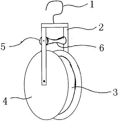
图1为防跳线、卡线光缆直线滑车的结构示意图。 Fig. 1 is a structural schematic diagram of the anti-jumping and stuck optical cable linear pulley.
具体实施方式 Detailed ways
下面结合附图对本实用新型所提出的防跳线、卡线光缆直线滑车的结构做进一步说明。 Below in conjunction with accompanying drawing, the structure of the anti-jump line proposed by the utility model and the clamped optical cable linear block will be further described.
如图1所示,为防跳线、卡线光缆直线滑车的结构示意图。其结构包括上端带有挂钩1的滑轮架2和带有第一线槽3的第一滑轮4,在第一滑轮4上方的滑轮架2上设置有第二滑轮5,在第二滑轮5中部设置有第二线槽6。在进行放紧线、张力放线时,当两边杆塔高,中间杆塔低时,牵引绳、光缆也不会离开滑车的第一线槽和第二线槽,有效地防止跳线和卡线现象的发生,避免了因跳线和卡线造成的安全事故,工作效率大大提高。
As shown in Figure 1, it is a schematic structural diagram of the anti-jumping and jammed optical cable linear pulley. Its structure includes a
第二滑轮5的直径小于第一滑轮4的直径,这样,滑轮架2的高度不需要增加或仅仅少量增加,便于施工。
The diameter of the second pulley 5 is smaller than the diameter of the
第二滑轮5与第一滑轮边缘距离为0.5厘米,防止了牵引绳或光缆移出第一线槽和第二线槽。 The distance between the second pulley 5 and the edge of the first pulley is 0.5 centimeter, which prevents the traction rope or optical cable from moving out of the first wire groove and the second wire groove.
本实用新型的保护范围不仅仅局限于上述实施例,只要结构与本实用新型防跳线、卡线光缆直线滑车结构相同,就落在本实用新型保护的范围。 The scope of protection of the utility model is not only limited to the above-mentioned embodiments, as long as the structure is the same as that of the utility model anti-jump wire and clamping optical cable linear pulley, it falls within the scope of protection of the utility model.
Claims (3)
Priority Applications (1)
| Application Number | Priority Date | Filing Date | Title |
|---|---|---|---|
| CN 201220574598 CN202837643U (en) | 2012-11-05 | 2012-11-05 | Anti-wire jumping and wire clamping optical cable linear tackle |
Applications Claiming Priority (1)
| Application Number | Priority Date | Filing Date | Title |
|---|---|---|---|
| CN 201220574598 CN202837643U (en) | 2012-11-05 | 2012-11-05 | Anti-wire jumping and wire clamping optical cable linear tackle |
Publications (1)
| Publication Number | Publication Date |
|---|---|
| CN202837643U true CN202837643U (en) | 2013-03-27 |
Family
ID=47949318
Family Applications (1)
| Application Number | Title | Priority Date | Filing Date |
|---|---|---|---|
| CN 201220574598 Expired - Fee Related CN202837643U (en) | 2012-11-05 | 2012-11-05 | Anti-wire jumping and wire clamping optical cable linear tackle |
Country Status (1)
| Country | Link |
|---|---|
| CN (1) | CN202837643U (en) |
Cited By (2)
| Publication number | Priority date | Publication date | Assignee | Title |
|---|---|---|---|---|
| CN103387159A (en) * | 2013-08-02 | 2013-11-13 | 常熟市沪虞港口机械有限公司 | Wire jump preventer used in textile machine |
| CN113644589A (en) * | 2021-05-25 | 2021-11-12 | 国网河北省电力有限公司邯郸供电分公司 | A fully enclosed construction protection pulley for high-voltage transmission lines |
-
2012
- 2012-11-05 CN CN 201220574598 patent/CN202837643U/en not_active Expired - Fee Related
Cited By (3)
| Publication number | Priority date | Publication date | Assignee | Title |
|---|---|---|---|---|
| CN103387159A (en) * | 2013-08-02 | 2013-11-13 | 常熟市沪虞港口机械有限公司 | Wire jump preventer used in textile machine |
| CN103387159B (en) * | 2013-08-02 | 2015-11-18 | 太仓市天合新材料科技有限公司 | A kind of for the wire jumping prevention device in textile machine |
| CN113644589A (en) * | 2021-05-25 | 2021-11-12 | 国网河北省电力有限公司邯郸供电分公司 | A fully enclosed construction protection pulley for high-voltage transmission lines |
Similar Documents
| Publication | Publication Date | Title |
|---|---|---|
| CN201708479U (en) | Cable stretching construction cross pulley | |
| CN203531496U (en) | Falling type double-holding-rod pole erecting device | |
| CN203434532U (en) | Safety auxiliary device for vertical cable laying | |
| CN202423978U (en) | Overhead wire crossing frame | |
| CN201367332Y (en) | Variable hoisting pulley block | |
| CN102394485A (en) | Steel stranded wire clamping device | |
| CN205150975U (en) | Tensioning device of winch | |
| CN202094542U (en) | Improved pulley used for electric power line intersection and crossing construction | |
| CN201907879U (en) | Automatic take-up device for water tank | |
| CN203632097U (en) | Double-side motor transmission double-grooved-pulley stringing apparatus | |
| CN202651687U (en) | A tumbler used to remove foreign objects on power lines | |
| CN204173711U (en) | For the guiding anti-wobble mechanism of iron tower of power transmission line jacking system | |
| CN203743308U (en) | Rope fastening device of hoisting device | |
| CN201670675U (en) | Crane cable wire tripping-prevention device | |
| CN202678829U (en) | Wear-proof pulley for paying off overhead grounding wires | |
| CN202059099U (en) | Double-string tension insulator wire-tightening hook | |
| CN203541372U (en) | Butt-welded reinforcing steel bar straightening mechanism | |
| CN204680989U (en) | A kind of damping flying car for overhauling overhead ground wire | |
| CN202936030U (en) | Steel wire rope automatic winding frame | |
| CN202034123U (en) | Anti-vibration device for feeding wires in handpiece of crosslinking production line | |
| CN204732790U (en) | A kind of lead wire and earth wire in transmission line pulley block device | |
| CN202488032U (en) | Insulator cradle capable of changing 330kV power transmission line strain glass composite insulator | |
| CN203278104U (en) | Paying-off tackle for corner of cable draw pit | |
| CN202678913U (en) | External-support steel wire rope wear-proof pulley | |
| CN203632096U (en) | Single-pulley self-transmission type stringing apparatus |
Legal Events
| Date | Code | Title | Description |
|---|---|---|---|
| C14 | Grant of patent or utility model | ||
| GR01 | Patent grant | ||
| ASS | Succession or assignment of patent right |
Owner name: STATE ELECTRIC NET CROP. Free format text: FORMER OWNER: HENGSHUI POWER SUPPLY COMPANY Effective date: 20131212 Owner name: HENGSHUI POWER SUPPLY BRANCH COMPANY, STATE GRID H Free format text: FORMER OWNER: STATE ELECTRIC NET CROP. HEBEI ELECTRIC POWER CORPORATION Effective date: 20131212 |
|
| C41 | Transfer of patent application or patent right or utility model | ||
| COR | Change of bibliographic data |
Free format text: CORRECT: ADDRESS; FROM: 053000 HENGSHUI, HEBEI PROVINCE TO: 100031 XICHENG, BEIJING |
|
| TR01 | Transfer of patent right |
Effective date of registration: 20131212 Address after: 100031 Xicheng District West Chang'an Avenue, No. 86, Beijing Patentee after: State Grid Corporation of China Patentee after: Hengshui Power Supply Branch, State Grid Hebei Electric Power Co., Ltd. Patentee after: State Grid Hebei Electric Power Company Address before: 053000 Hengshui East Road, Hebei, No. 185 Patentee before: Hengshui Power Supply Company Patentee before: State Grid Corporation of China Patentee before: Hebei Electric Power Corporation |
|
| CF01 | Termination of patent right due to non-payment of annual fee |
Granted publication date: 20130327 Termination date: 20171105 |
|
| CF01 | Termination of patent right due to non-payment of annual fee |