CN202827818U - Car spare tire lifting device - Google Patents
Car spare tire lifting device Download PDFInfo
- Publication number
- CN202827818U CN202827818U CN 201220485273 CN201220485273U CN202827818U CN 202827818 U CN202827818 U CN 202827818U CN 201220485273 CN201220485273 CN 201220485273 CN 201220485273 U CN201220485273 U CN 201220485273U CN 202827818 U CN202827818 U CN 202827818U
- Authority
- CN
- China
- Prior art keywords
- swing arm
- spare tire
- vehicle frame
- lower swing
- top link
- Prior art date
- Legal status (The legal status is an assumption and is not a legal conclusion. Google has not performed a legal analysis and makes no representation as to the accuracy of the status listed.)
- Expired - Fee Related
Links
Images


Landscapes
- Handcart (AREA)
Abstract
本实用新型公开了一种汽车备胎升降装置,本实用新型包括上摆臂、下摆臂和备胎固定架,上摆臂和下摆臂的上下两端分别与车架和备胎固定架连接,上摆臂、下摆臂、车架和备胎固定架连接成一个平行四边形机构,平行四边形机构中位于车架上的边是竖向的,车架上设有驱动上摆臂或下摆臂绕其在车架上的铰接点转动的驱动机构。本实用新型由于平行四边形机构中位于车架上的边是竖向的,因此备胎固定支架一直是竖向升降的,备胎在竖直固定在备胎固定支架上,使得备胎纵向布置,因此能使备胎在升降过程中始终保持竖直状态,节省升降空间,便于在车上安装,并且能保证落到地面的备胎竖立,便于安装。
The utility model discloses a lifting device for a spare tire of an automobile. The utility model comprises an upper swing arm, a lower swing arm and a spare tire fixing frame. The upper and lower ends of the upper swing arm and the lower swing arm are respectively connected with the vehicle frame and the spare tire fixing frame. The upper swing arm, the lower swing arm, the vehicle frame and the spare tire fixing bracket are connected to form a parallelogram mechanism, the side of the parallelogram mechanism on the vehicle frame is vertical, and the vehicle frame is provided with a driving upper swing arm or a lower swing arm around it. A drive mechanism that rotates at a hinge point on the frame. In the utility model, since the side on the vehicle frame in the parallelogram mechanism is vertical, the spare tire fixing bracket is always vertically lifted, and the spare tire is vertically fixed on the spare tire fixing bracket, so that the spare tire is vertically arranged, Therefore, the spare tire can be kept in a vertical state during the lifting process, the lifting space is saved, and it is convenient to install on the car, and the spare tire that has fallen to the ground can be guaranteed to be upright, which is convenient for installation.
Description
技术领域 technical field
本实用新型涉及一种汽车备胎升降装置。 The utility model relates to a lifting device for a spare tire of an automobile.
背景技术 Background technique
随着自动化技术的飞速发展,方便、快捷,且省时、省力的汽车备胎升降装置越来越多的应用到载重汽车上。然而,目前的大多数汽车备胎升降装置,都采用备胎横向放置,这样限制了整车布置。 With the rapid development of automation technology, more and more convenient, fast, time-saving and labor-saving automobile spare tire lifting devices are applied to trucks. Yet most of present automobile spare tire lifting devices all adopt spare tire to place laterally, have limited like this whole vehicle arrangement. the
发明内容 Contents of the invention
本实用新型要解决的技术问题是:提供一种便于备胎纵向布置的汽车备胎升降装置。 The technical problem to be solved by the utility model is to provide an automobile spare tire lifting device which is convenient for the vertical arrangement of the spare tire.
为了解决上述技术问题,本实用新型包括上摆臂、下摆臂和备胎固定架,上摆臂和下摆臂的上下两端分别与车架和备胎固定架连接,上摆臂、下摆臂、车架和备胎固定架连接成一个平行四边形机构,平行四边形机构中位于车架上的边是竖向的,车架上设有驱动上摆臂或下摆臂绕其在车架上的铰接点转动的驱动机构。 In order to solve the above-mentioned technical problems, the utility model comprises an upper swing arm, a lower swing arm and a spare tire fixing frame, the upper and lower ends of the upper swing arm and the lower swing arm are respectively connected with the vehicle frame and the spare tire fixing frame, The frame and the spare tire fixing bracket are connected to form a parallelogram mechanism, the side of the parallelogram mechanism on the frame is vertical, and the frame is provided with hinge points that drive the upper swing arm or the lower swing arm around it on the frame Rotary drive mechanism.
所述的驱动机构包括油泵和油缸,上摆臂和下摆臂各通过各自的固定座与车架连接,上摆臂和下摆臂与固定座铰接,固定座固定在车架上,油缸的一端与上摆臂连接,油缸的另一端与上摆臂的固定座的连接,油缸连接油泵,油泵设置在车架上。 The driving mechanism includes an oil pump and an oil cylinder. The upper swing arm and the lower swing arm are connected to the vehicle frame through respective fixing seats, the upper swing arm and the lower swing arm are hinged to the fixing seats, and the fixing seats are fixed on the vehicle frame. The upper swing arm is connected, the other end of the oil cylinder is connected with the fixed seat of the upper swing arm, the oil cylinder is connected with an oil pump, and the oil pump is arranged on the vehicle frame.
为了便于在双前轴汽车上布置,所述的上摆臂和下摆臂均包括两个杆体,两个杆体的中间靠拢两端叉开。 In order to be conveniently arranged on a double-front-axle vehicle, the upper swing arm and the lower swing arm both include two rod bodies, and the middle of the two rod bodies is close to each other and the two ends are forked.
本实用新型的有益效果是:本实用新型通过上、下摆臂与备胎固定支架与车架之间形成平行四边形机构以对备胎提供升降功能,由于平行四边形机构中位于车架上的边是竖向的,因此备胎固定支架一直是竖向升降的,备胎在竖直固定在备胎固定支架上,使得备胎纵向布置,因此能使备胎在升降过程中始终保持竖直状态,节省升降空间,便于在车上安装,并且能保证落到地面的备胎竖立,便于安装。 The beneficial effects of the utility model are: the utility model forms a parallelogram mechanism between the upper and lower swing arms, the spare tire fixing bracket and the vehicle frame to provide lifting function for the spare tire, because the side on the vehicle frame in the parallelogram mechanism is Vertical, so the spare tire fixing bracket is always vertically lifted, and the spare tire is vertically fixed on the spare tire fixing bracket, so that the spare tire is vertically arranged, so that the spare tire can always maintain a vertical state during the lifting process, It saves lifting space, is easy to install on the car, and can ensure that the spare tire that has fallen to the ground is upright, which is easy to install.
附图说明 Description of drawings
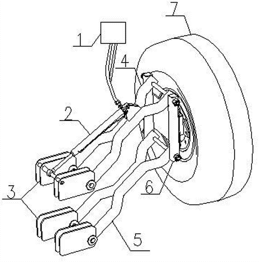
图1为本实用新型的结构示意图; Fig. 1 is the structural representation of the utility model;
图2为本实用新型初始状态的结构示意图; Figure 2 is a structural schematic diagram of the initial state of the utility model;
图3为本实用新型最终状态的结构示意图; Fig. 3 is the structural representation of the final state of the utility model;
图4为图1中件4、5和6的结构示意放大图;
Fig. 4 is the schematic enlarged view of the structure of
图中:1、油泵,2、举升缸,3、固定座;4、上摆臂,5、下摆臂,6、备胎固定支架,7、备胎。 In the figure: 1. Oil pump, 2. Lift cylinder, 3. Fixed seat; 4. Upper swing arm, 5. Lower swing arm, 6. Spare tire fixing bracket, 7. Spare tire.
具体实施方式 Detailed ways
如图1-图2所示的一种具体实施例,它包括油泵1、举升缸2和升降装置,所述升降装置包括上摆臂4、下摆臂5和备胎固定支架6,上摆臂4和下摆臂5一端各通过一个固定座3与车架连接,上摆臂4和下摆臂5与固定座3铰接,固定座3固定在车架上,上摆臂4和下摆臂5的另一端与备胎固定支架6铰接连接;举升缸2铰接连接在上摆臂4和上摆臂4的固定座之间;如图4所示,上摆臂4和下摆臂5平行并且长度相等,这样上摆臂4、下摆臂5、车架和备胎固定支架6构成双曲柄机构即平行四边形机构。平行四边形机构中位于车架上的边是竖向的。
A specific embodiment as shown in Figures 1-2, it includes an oil pump 1, a
上摆臂4和下摆臂5均包括两个杆体,两个杆体的中间靠拢两端叉开。这样上摆臂4和下摆臂5的两端各有两个连接点,稳定性好,而中间部分较窄,便于在双前轴汽车上应用,上下摆臂在上下摆动时中间部分可以通过双前轴汽车两个车轮间的间隙,便于布置。
Both the upper swing arm 4 and the
工作原理: working principle:
备胎7固定在备胎固定支架6上,本实用新型充分运用双曲柄机构即平行四边形机构运动特点:两个曲柄以相同的角速度作同向转动,而连杆作平动。使备胎7始终以纵向竖直状态,完成升降运动。 The spare tire 7 is fixed on the spare tire fixing support 6. The utility model fully utilizes the double crank mechanism, that is, the movement characteristics of the parallelogram mechanism: the two cranks rotate in the same direction at the same angular velocity, and the connecting rod performs translational motion. Make the spare tire 7 complete the lifting motion with the longitudinal vertical state all the time. the
本装置的初始状态如图2所示,平行四边形机构处于收起状态。 The initial state of the device is shown in Figure 2, and the parallelogram mechanism is in the retracted state.
当需要更换备胎时,在油泵1和举升缸2推动下,平行四边形机构的双曲柄即上、下摆臂同时同向以等角速度向下转动,随即推动备胎架作平动,使备胎7始终保持竖直状态直至备胎7落到底面,如图3所示。备胎7收起时,举升机构以相同状态反向运动,直至备胎7收起,如图2所示。
When it is necessary to replace the spare tire, under the push of the oil pump 1 and the
Claims (3)
Priority Applications (1)
| Application Number | Priority Date | Filing Date | Title |
|---|---|---|---|
| CN 201220485273 CN202827818U (en) | 2012-09-21 | 2012-09-21 | Car spare tire lifting device |
Applications Claiming Priority (1)
| Application Number | Priority Date | Filing Date | Title |
|---|---|---|---|
| CN 201220485273 CN202827818U (en) | 2012-09-21 | 2012-09-21 | Car spare tire lifting device |
Publications (1)
| Publication Number | Publication Date |
|---|---|
| CN202827818U true CN202827818U (en) | 2013-03-27 |
Family
ID=47939586
Family Applications (1)
| Application Number | Title | Priority Date | Filing Date |
|---|---|---|---|
| CN 201220485273 Expired - Fee Related CN202827818U (en) | 2012-09-21 | 2012-09-21 | Car spare tire lifting device |
Country Status (1)
| Country | Link |
|---|---|
| CN (1) | CN202827818U (en) |
Cited By (1)
| Publication number | Priority date | Publication date | Assignee | Title |
|---|---|---|---|---|
| CN102849129A (en) * | 2012-09-21 | 2013-01-02 | 中国重汽集团济南动力有限公司 | Lifting device for automobile spare tire |
-
2012
- 2012-09-21 CN CN 201220485273 patent/CN202827818U/en not_active Expired - Fee Related
Cited By (1)
| Publication number | Priority date | Publication date | Assignee | Title |
|---|---|---|---|---|
| CN102849129A (en) * | 2012-09-21 | 2013-01-02 | 中国重汽集团济南动力有限公司 | Lifting device for automobile spare tire |
Similar Documents
| Publication | Publication Date | Title |
|---|---|---|
| CN204506350U (en) | Lateral wheel is apart from telescopic devices | |
| CN103317987B (en) | The free landing cross-country car of a kind of wheel | |
| CN201633469U (en) | The Folding Wheel Mechanism of Agricultural High Clearance Spraying Vehicle | |
| CN103010181B (en) | Auxiliary parking device and electric vehicle having device | |
| CN204196608U (en) | Novel tyre detacher | |
| CN102555709B (en) | Winding and releasing device for wheels of amphibious vehicle | |
| CN203402170U (en) | Brake assistance device of car | |
| CN203419691U (en) | A rotary hoisting device | |
| CN103161185A (en) | Slipping loading machine perpendicular lift device | |
| CN204659700U (en) | Automatic lifting parallel shifted formula automobile chassis device | |
| CN205202634U (en) | Two yoke suspension hoisting device | |
| CN102849129A (en) | Lifting device for automobile spare tire | |
| CN202829496U (en) | Parallel four-bar lifting mechanism | |
| CN202345647U (en) | Pivot steering system of automobile with two-stage driving | |
| CN204998655U (en) | Vehicle conveying aluminum ladles | |
| CN202271794U (en) | Hydraulic hanging device for large-journey vehicle | |
| CN204037273U (en) | The cross-country car that a kind of chassis height is adjustable | |
| CN202156459U (en) | A folding tailgate device | |
| CN204279384U (en) | A kind of fluid pressure type apparatus for moving vehicle | |
| CN202152023U (en) | Swing arm type supporting and hanging combination device | |
| CN201895717U (en) | Quick-change type hydraulic lift spare tire carrier device | |
| CN202806519U (en) | Lifting mechanism of road wrecker | |
| CN104163085B (en) | Automobile wheel tread adjusting device | |
| CN203201192U (en) | Roadside parking device | |
| CN204567808U (en) | Entire vehicle formula lifting gear |
Legal Events
| Date | Code | Title | Description |
|---|---|---|---|
| C14 | Grant of patent or utility model | ||
| GR01 | Patent grant | ||
| CF01 | Termination of patent right due to non-payment of annual fee |
Granted publication date: 20130327 Termination date: 20150921 |
|
| EXPY | Termination of patent right or utility model |