CN202826496U - Hydraulic clutch structure of press machine - Google Patents
Hydraulic clutch structure of press machine Download PDFInfo
- Publication number
- CN202826496U CN202826496U CN 201220498374 CN201220498374U CN202826496U CN 202826496 U CN202826496 U CN 202826496U CN 201220498374 CN201220498374 CN 201220498374 CN 201220498374 U CN201220498374 U CN 201220498374U CN 202826496 U CN202826496 U CN 202826496U
- Authority
- CN
- China
- Prior art keywords
- clutch
- push
- braking platen
- lever
- pull
- Prior art date
- Legal status (The legal status is an assumption and is not a legal conclusion. Google has not performed a legal analysis and makes no representation as to the accuracy of the status listed.)
- Expired - Fee Related
Links
- 230000007246 mechanism Effects 0.000 claims description 18
- 238000010276 construction Methods 0.000 claims description 6
- 238000000926 separation method Methods 0.000 abstract 2
- 239000003921 oil Substances 0.000 description 13
- 230000009471 action Effects 0.000 description 4
- 230000000694 effects Effects 0.000 description 4
- 230000003321 amplification Effects 0.000 description 3
- 238000003199 nucleic acid amplification method Methods 0.000 description 3
- 239000010720 hydraulic oil Substances 0.000 description 2
- 230000000712 assembly Effects 0.000 description 1
- 238000000429 assembly Methods 0.000 description 1
- 230000009286 beneficial effect Effects 0.000 description 1
- 230000005540 biological transmission Effects 0.000 description 1
- 230000008859 change Effects 0.000 description 1
- 239000008358 core component Substances 0.000 description 1
- 238000010586 diagram Methods 0.000 description 1
- 238000005516 engineering process Methods 0.000 description 1
- 239000012467 final product Substances 0.000 description 1
- 239000012530 fluid Substances 0.000 description 1
- 210000004907 gland Anatomy 0.000 description 1
- 230000006872 improvement Effects 0.000 description 1
- 238000000034 method Methods 0.000 description 1
- 230000004044 response Effects 0.000 description 1
- 230000000007 visual effect Effects 0.000 description 1
Images

Landscapes
- Control Of Presses (AREA)
Abstract
The utility model provides a hydraulic clutch structure of press machine. The hydraulic clutch of press machine comprises a clutch-housing (1), a clutch cover (2) matched with the clutch-housing (1), a braking platen (6) installed in the clutch-housing (1), a spring assembly between the braking platen (6) and the clutch over (2), and a push-pull structure of the braking platen. The push-pull structure of the braking platen is more than two. The push-pull structure of the braking platen comprises a hydro-cylinder (3) which is fixed on the clutch-housing (1), and a lever structure and a push-pull rod (5). The lever structure is mounted on the clutch over (2). One end of the lever structure is connected with a piston head of the hydro-cylinder (3) and the other end of the lever structure is in hinge mode with the push-pull rod (5). The other end of the push-pull rod (5) is fixed with the braking platen (6). The hydraulic clutch of press machine has the advantages of large torque of separation and reunion, stable separation and reunion, and small size.
Description
Technical field
The utility model relates to field of mechanical technique, relates in particular to hydraulic clutch, specifically refers to a kind of forcing press hydraulic clutch structure.
Background technology
Because the hydraulic clutch of high-speed blanking press is the forcing press vital part, plays safe and reliable connection flywheel and bent axle, perhaps separates the effect of flywheel and bent axle.Traditional hydraulic clutch usually only adopts in the direct driving clutch of large tank and brakes platen, clutch moment is little when clutch, clutch is not steady, volume is larger, structural design is unreasonable, at heavy load and require in the situation of clutch exactly, easily causing can not be reliably, connect accurately, separate flywheel and bent axle, affects the normal use of complete machine, brings hidden danger and inconvenience to production work.
The utility model content
Primary technical problem to be solved in the utility model is, provide that a kind of clutch moment is large, clutch steadily and the forcing press hydraulic clutch structure of small volume, on this basis, the purpose of this utility model also is further to improve to realize that clutch is more steady, the effect of clutch fast response time.
Technical solution of the present utility model is, a kind of forcing press hydraulic clutch structure is provided, comprise clutch housing, the clutch case that matches with clutch housing, be located at the braking platen in the clutch housing, be located at spring assembly and braking platen push-pull mechanism between braking platen and the clutch case, described braking platen push-pull mechanism is provided with at least two groups, described braking platen push-pull mechanism comprises the oil cylinder that is fixed on the clutch housing, leverage and pull bar, described lever construction is located on the clutch case, the two ends of lever construction are hinged with an end of the piston head of oil cylinder and pull bar respectively, and the other end of described pull bar is fixedly connected with the braking platen.
After adopting above scheme, the utility model forcing press hydraulic clutch structure has adopted at least two group brake disc push-pull mechanisms that the braking platen is realized push pull maneuver, and the middle push pull maneuver of utilizing leverage to come Indirect driven braking platen, each oil cylinder does not need to export the push pull maneuver that too large power can be finished the braking platen so on the one hand, therefore can adopt can the satisfy the demand needs of high-torque braking of miniature oil cylinder, in addition, the scheme that the utility model adopts is owing to be to have utilized at least two group brake disc push-pull mechanisms that brake is carried out braking maneuver, so the clutch effect is comparatively steady.Therefore the utlity model has that clutch moment is large, clutch steadily and the small volume beneficial effect.
As preferably, described leverage comprises that an end is fixed on clutch case upper lever support and the lever hinged with lever dolly, and the two ends of described lever are hinged with an end of the piston head of oil cylinder and pull bar respectively.This preferred version adopts a simple lever principle to realize the amplification of oil cylinder output torque, and multiplication factor can be adjusted with the length of the arm of force of lever two hinged ends by adjusting lever dolly, and is simple in structure, is convenient to enforcement.
As preferably, described braking platen push-pull mechanism distributes along even circumferential at brake cap.Stressed even when this preferred version brake force imposes on the braking platen, braking steadily.
As preferably, described brake disc push-pull mechanism is provided with four groups.This preferred version adopts four groups of brake disc push-pull mechanisms that the braking platen is carried out push pull maneuver, and rational in infrastructure, braking moment is large.
As preferably, the quantity of described spring assembly is four groups.This preferred version can easily be realized flywheel and bent axle separating action, realizes reliably, separates rapidly.
Description of drawings
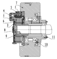
Fig. 1 is main TV structure schematic diagram of the present utility model.
Fig. 2 is A-A directional profile structural representation among Fig. 1.
Shown in the figure:
1, clutch housing 1,2, clutch case, 3, oil cylinder, 4, lever, 5, pull bar, 6, the braking platen, 7, flywheel, 8, the clutch shaft end cap, 9, bent axle, 10, bearing, 11, bearing gland, 12, lever dolly.
The specific embodiment
For ease of explanation, below in conjunction with accompanying drawing, forcing press hydraulic clutch structure of the present utility model is elaborated:
As shown in Fig. 1 and Fig. 2, a kind of forcing press hydraulic clutch structure, comprise clutch housing 1, the clutch case 2 that matches with clutch housing 1, be located at the braking platen 6 in the clutch housing 1, be located at four groups of spring assemblies between braking platen 6 and the clutch case 2 and brake the platen push-pull mechanism, described braking platen push-pull mechanism is provided with at least two groups, described braking platen push-pull mechanism comprises the oil cylinder 3 that is fixed on the clutch housing 1, leverage and pull bar 5, described lever construction is located on the clutch case 2, the two ends of lever construction are hinged with an end of the piston head of oil cylinder 3 and pull bar 5 respectively, the other end of described pull bar 5 is fixedly connected with braking platen 6, described leverage comprises that an end is fixed on clutch case 2 upper lever supports 12 and the lever 4 hinged with lever dolly 12, the two ends of described lever 4 are hinged with an end of the piston head of oil cylinder 3 and pull bar 5 respectively, and described braking platen push-pull mechanism distributes along even circumferential at clutch case 2; In the present embodiment, described brake disc push-pull mechanism is provided with four groups, and the quantity of described spring assembly is four groups.
When work, four oil cylinder 3 cylinder body hydraulic fluid ports pass into hydraulic oil, piston driving lever 4 is to left movement, moment amplification by 12 outputs of lever dolly, lever 4 drives pull bar 5 and moves right, pull bar 5 drive braking platens 6 move right, and this moment, brake disc can link together with the braking platen, and clutch is finished the action of flywheel 7 and bent axle 9 combinations; During reverse operation, the hydraulic oil pressure release, piston moves right under the effect of spring assembly, drives simultaneously braking platen 6 to left movement, brakes platen 6 this moment and separates with brake disc, realizes the separating action of flywheel 7 and bent axle 9.
Also should illustrate at this, above-described embodiment is only to crucial must the statement by core component among the embodiment, in the specific implementation, the mode that the clutch that the utility model is mentioned adopts brake disc and braking platen to combine realizes clutch, the braking platen 6 that the utility model is mentioned is for playing the braking platen of actual active pressuring action, the oil cylinder that the utility model uses can adopt the oil cylinder of prior art to get final product, mounting structure etc. is prior art between its concrete structure and mounting means and clutch and the bent axle, the utility model does not relate to the improvement to these prior aries, therefore, the utility model specification repeats no more this part prior art content.
In the above-described embodiments, preferred forms of the present utility model is described, obviously, under inventive concept of the present utility model, still can make a lot of variations, the quantity of the spring assembly as described also size of visual actual clutching force is adjusted, and described leverage also can adopt the multi-grade lever pair to carry out transmission with purpose of reaching larger moment amplification etc. for another example.At this, should illustrate that any change of making all will fall in the protection domain of the present utility model under inventive concept of the present utility model.
Claims (5)
1. forcing press hydraulic clutch structure, comprise clutch housing (1), the clutch case (2) that matches with clutch housing (1), be located at the braking platen (6) in the clutch housing (1), be located at spring assembly and braking platen push-pull mechanism between braking platen (6) and the clutch case (2), it is characterized in that: described braking platen push-pull mechanism is provided with at least two groups, described braking platen push-pull mechanism comprises the oil cylinder (3) that is fixed on the clutch housing (1), leverage and pull bar (5), described lever construction is located on the clutch case (2), the two ends of lever construction are hinged with an end of the piston head of oil cylinder (3) and pull bar (5) respectively, and the other end of described pull bar (5) is fixedly connected with braking platen (6).
2. forcing press hydraulic clutch structure according to claim 1, it is characterized in that: described leverage comprises that an end is fixed on clutch case (2) upper lever support (12) and the lever (4) hinged with lever dolly (12), and the two ends of described lever (4) are hinged with an end of the piston head of oil cylinder (3) and pull bar (5) respectively.
3. forcing press hydraulic clutch structure according to claim 1, it is characterized in that: described braking platen push-pull mechanism distributes along even circumferential at clutch case (2).
4. according to claim 1 to the described forcing press hydraulic clutch of 3 arbitrary claims structure, it is characterized in that: described brake disc push-pull mechanism is provided with four groups.
5. forcing press hydraulic clutch structure according to claim 4, it is characterized in that: the quantity of described spring assembly is four groups.
Priority Applications (1)
| Application Number | Priority Date | Filing Date | Title |
|---|---|---|---|
| CN 201220498374 CN202826496U (en) | 2012-09-27 | 2012-09-27 | Hydraulic clutch structure of press machine |
Applications Claiming Priority (1)
| Application Number | Priority Date | Filing Date | Title |
|---|---|---|---|
| CN 201220498374 CN202826496U (en) | 2012-09-27 | 2012-09-27 | Hydraulic clutch structure of press machine |
Publications (1)
| Publication Number | Publication Date |
|---|---|
| CN202826496U true CN202826496U (en) | 2013-03-27 |
Family
ID=47938281
Family Applications (1)
| Application Number | Title | Priority Date | Filing Date |
|---|---|---|---|
| CN 201220498374 Expired - Fee Related CN202826496U (en) | 2012-09-27 | 2012-09-27 | Hydraulic clutch structure of press machine |
Country Status (1)
| Country | Link |
|---|---|
| CN (1) | CN202826496U (en) |
Cited By (1)
| Publication number | Priority date | Publication date | Assignee | Title |
|---|---|---|---|---|
| CN102862315A (en) * | 2012-09-27 | 2013-01-09 | 山东金箭精密机器有限公司 | Hydraulic clutch structure of pressure machine |
-
2012
- 2012-09-27 CN CN 201220498374 patent/CN202826496U/en not_active Expired - Fee Related
Cited By (2)
| Publication number | Priority date | Publication date | Assignee | Title |
|---|---|---|---|---|
| CN102862315A (en) * | 2012-09-27 | 2013-01-09 | 山东金箭精密机器有限公司 | Hydraulic clutch structure of pressure machine |
| CN102862315B (en) * | 2012-09-27 | 2015-11-04 | 山东金箭精密机器有限公司 | Press hydraulic clutch structure |
Similar Documents
| Publication | Publication Date | Title |
|---|---|---|
| CN204093900U (en) | Direct-drive type toggle link hydraulic press | |
| CN201645850U (en) | Main driving mechanism of hydraulic servo press | |
| CN102862315B (en) | Press hydraulic clutch structure | |
| CN202826495U (en) | Hydraulic brake structure of press machine | |
| CN204548061U (en) | Middle power wheeled tractor the hydrostatic braking maneuvering system | |
| CN201521574U (en) | Direct-pushing type single-cylinder normally-closed brake | |
| CN203477291U (en) | Transmission gear selection return device | |
| CN203453333U (en) | Hydraulic clutch | |
| CN202574253U (en) | Hydraulic brake shoe type braking device for mine electric locomotive | |
| CN201934632U (en) | Speed reducer for rolling miller | |
| CN204403209U (en) | A kind of novel railway station squadrol clutch | |
| CN104455062A (en) | Novel railway station cruiser clutch | |
| CN202991952U (en) | Braking device of shaft lever | |
| CN202402512U (en) | Structure of clutch of brick making machine | |
| CN102825829B (en) | Forcing press Hydraulic brake structure | |
| CN101947583B (en) | Core pulling device on pipe bending machine | |
| CN201241728Y (en) | Carrying scraper with gear box having parking brake | |
| CN201100351Y (en) | Arrester pressure adjusting structure | |
| CN207864464U (en) | A kind of free-standing double-action clutch of big-power tractor | |
| CN203528724U (en) | Brake device used for mechanical disc brake of bicycle | |
| CN201621213U (en) | Direct pushing type single-cylinder normally open brake | |
| CN206328087U (en) | A kind of brake for crane | |
| CN203730617U (en) | Break caliper with gap adjustment function | |
| CN209869503U (en) | Adjustable clutch device of press machine | |
| CN202674122U (en) | Dry-type pneumatic double-plate friction clutch brake |
Legal Events
| Date | Code | Title | Description |
|---|---|---|---|
| C14 | Grant of patent or utility model | ||
| GR01 | Patent grant | ||
| CF01 | Termination of patent right due to non-payment of annual fee |
Granted publication date: 20130327 Termination date: 20160927 |
|
| CF01 | Termination of patent right due to non-payment of annual fee |