CN202804518U - Welding gun support - Google Patents
Welding gun support Download PDFInfo
- Publication number
- CN202804518U CN202804518U CN 201220394087 CN201220394087U CN202804518U CN 202804518 U CN202804518 U CN 202804518U CN 201220394087 CN201220394087 CN 201220394087 CN 201220394087 U CN201220394087 U CN 201220394087U CN 202804518 U CN202804518 U CN 202804518U
- Authority
- CN
- China
- Prior art keywords
- welding gun
- crossbeam
- pillar
- spacing hole
- welding
- Prior art date
- Legal status (The legal status is an assumption and is not a legal conclusion. Google has not performed a legal analysis and makes no representation as to the accuracy of the status listed.)
- Expired - Fee Related
Links
Images

Abstract
The utility model provides a welding gun support which is used in the technical field of welding devices. The welding gun support comprises a brace (1), a cross beam (2) which can rotate around the brace (1) is arranged at the upper end of the brace (1) in a movable mode, the cross beam is provided with a welding gun (3), and a tool platform (5) which can be used for placing to-be-welded workpieces is arranged below the cross beam (2). According to the welding gun support, an operator can rotate the cross beam to a position where the cross beam leaves the tool platform and above the tool platform, at the time, the fact that a crane lifts the to-be-welded workpieces can not be affected by the cross beam, so that the to-be-welded workpieces can be conveyed to the tool platform conveniently. After the welding gun is arranged in a penetrating hole of a mounting beam in a clamping mode, welding can be conducted, in the process of welding, the platform surface of the tool platform is rotated, welding processing on different portions of the to-be-welded workpieces can be achieved, not only is the problem of unreasonable structure solved and the operating difficulty of the operator is lowered, but also the working efficiency of welding is improved, time is saved, and working speed is accelerated.
Description
Technical field
The utility model belongs to the welder technical field, more particularly, relates to a kind of welding gun support.
Background technology
In the prior art at present, when grinding roller carries out automatic surfacing at the tooling platform that can rotate, adopt fixed welding gun support, such structure, the welding gun support is fixing body, when workpiece to be welded when upper and lower, welding gun can not rotate, and causes welding work pieces because welding torch position can not move, and workpiece to be welded is difficult in place and dismounting, thereby make inefficiency, operating personnel's labour intensity is large.
The utility model content
Technical problem to be solved in the utility model is: for the deficiencies in the prior art, provide a kind of simple in structure, can realize that welding gun makes things convenient for the shift position, thereby improve the welding gun support of welding efficiency.
Solve above-described technical problem, the technical scheme that the utility model is taked is:
The utility model is a kind of welding gun support, and described welding gun support comprises pillar, and the activity installation of pillar upper end can be installed welding gun around the crossbeam of pillar rotation on the crossbeam, and described crossbeam below arranges the tooling platform that can place workpiece to be welded.
The upper end of described pillar is connected with fixed part, described firmware component is connected with crossbeam by hinge, tooling platform comprises base and table top, table top is set to the structure that can freely rotate around base, pillar and base are installed on the ground, described crossbeam is set to horizontally disposed structure, and welding gun is vertically mounted on the crossbeam.
The plate structure that described fixed part is set to take the shape of the letter U, the fixed part left part is fixedly connected with column, the fixed part right part is connected with crossbeam by hinge, on the crossbeam He on the column limiting plate I and limiting plate II are set respectively, spacing hole I and spacing hole II are set respectively on limiting plate I and the limiting plate II, crossbeam rotate in place when the tooling platform top position, and spacing hole I and spacing hole II are in coincidence status, and latch is set to pass simultaneously the structure of spacing hole I and spacing hole II.
Described crossbeam comprises cross-beam body section, mounting rail, cross-beam body section is connected with firmware component by hinge, cross-beam body section is connected with mounting rail by a plurality of strutbeams, a plurality of perforation are set on the mounting rail, welding gun is set to be installed on the structure in any one perforation, and cross-beam body section and mounting rail are arranged in parallel.
Described pillar is connected with the oblique pull post, and an end of oblique pull post is connected with the pars intermedia of pillar, and the other end of oblique pull post is connected with ground, and the oblique pull post is set to be the structure that is in tilted layout.
Adopt the technical solution of the utility model, can obtain following beneficial effect:
Welding gun support of the present utility model, can first the latch that interts in spacing hole I 15 and spacing hole II 16 be extracted, crossbeam namely is in rotary state, the operator can turn to crossbeam the position of leaving the tooling platform top, at this moment, crossbeam can not affect crane and lift by crane workpiece to be welded, thereby is convenient to Workpiece transfer to be welded to tooling platform.After welding gun snaps fitted to perforation on the mounting rail, can weld, in the welding process, can be by the table top of rotary fixture platform, can realize treating the soldering of the different parts of welding work pieces, so both solve in the past irrational mix design and reduced operating personnel's operation easier, improve again the operating efficiency of welding, save the time, accelerated speed of production.
Description of drawings
The below makes briefly bright to each accompanying drawing of this specification expressed content and the mark among the figure:
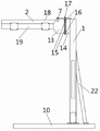
Fig. 1 is the positive TV structure structural representation of welding gun support described in the utility model;
Fig. 2 is the plan structure structural representation of the described welding gun support of Fig. 1;
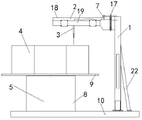
Fig. 3 is that welding gun support described in the utility model and tooling platform are faced structural representation when installing simultaneously on the ground;
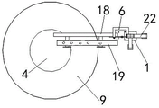
Fig. 4 is welding gun support described in the utility model and the tooling platform plan structure schematic diagram when installing simultaneously on the ground;
Be labeled as among the figure: 1, pillar; 2, crossbeam; 3, welding gun; 4, workpiece to be welded; 5, tooling platform; 6, fixed part; 7, hinge; 8, base; 9, table top; 10, ground; 11, fixed part left part; 12, fixed part right part; 13, limiting plate I; 14, limiting plate II; 15, spacing hole I; 16, spacing hole II; 17, latch; 18, cross-beam body section; 19, mounting rail; 20, strutbeam; 21, perforation; 22, oblique pull post.
The specific embodiment
The below contrasts accompanying drawing, by the description to embodiment, the effect of the mutual alignment between the shape of the specific embodiment of the present utility model such as related each member, structure, the each several part and annexation, each several part and operation principle etc. are described in further detail:
Shown in accompanying drawing 1-accompanying drawing 4, the utility model is a kind of welding gun support, and described welding gun support comprises pillar 1, and pillar 1 upper end activity installation can be around the crossbeam 2 of pillar 1 rotation, welding gun 3 is installed on the crossbeam 2, and described crossbeam 2 belows arrange the tooling platform 5 that can place workpiece 4 to be welded.
The upper end of described pillar 1 is connected with fixed part 6, described firmware component 6 is connected with crossbeam 2 by hinge 7, tooling platform 5 comprises base 8 and table top 9, table top 9 is set to the structure that can freely rotate around base 8, pillar 1 and base 8 are installed on the ground 10, described crossbeam 2 is set to horizontally disposed structure, and welding gun 3 is vertically mounted on the crossbeam 2.
The plate structure that described fixed part 6 is set to take the shape of the letter U, fixed part left part 11 is fixedly connected with column 1, fixed part right part 12 is connected with crossbeam 2 by hinge 7, on the crossbeam 2 He on the column 1 limiting plate I 13 and limiting plate II 14 are set respectively, spacing hole I 15 and spacing hole II 16 are set respectively on limiting plate I 13 and the limiting plate II 14, crossbeam 2 rotate in place when tooling platform 5 top position, spacing hole I 15 and spacing hole II 16 are in coincidence status, and latch 17 is set to pass simultaneously the structure of spacing hole I 15 and spacing hole II 16.
Described crossbeam 2 comprises cross-beam body section 18, mounting rail 19, cross-beam body section 18 is connected with firmware component 6 by hinge 7, cross-beam body section 18 is connected with mounting rail 19 by a plurality of strutbeams 20, a plurality of perforation 21 are set on the mounting rail 19, welding gun 3 is set to be installed on the structure in any one perforation 21, and described cross-beam body section 18 and mounting rail 19 are arranged in parallel.
Described pillar 1 is connected with oblique pull post 22, and an end of oblique pull post 22 is connected with the pars intermedia of pillar 1, and the other end of oblique pull post 22 is connected with ground 10, and oblique pull post 22 is set to be the structure that is in tilted layout.
Welding gun support of the present utility model, when needs are lifted to workpiece 4 to be welded on the tooling platform 5, can first the latch 17 that interts in spacing hole I 15 and spacing hole II 16 be extracted, at this moment, crossbeam 2 is in rotary state, the operator rotates horizontal 2 beams, crossbeam 2 rotates around hinge 7, crossbeam 2 can be turned to the position of leaving tooling platform 5 tops, at this moment, crossbeam 2 can not affect crane and lift by crane workpiece 4 to be welded, thereby be convenient to workpiece 4 to be welded is transplanted on the tooling platform 5, workpiece 4 to be welded needs to position at tooling platform 5, prevents play in welding process, thereby affects the welding quality of whole workpiece.Behind workpiece to be welded 4 location, can remove crane, rotating beam 2 is to the position of spacing hole I 15 and 16 coincidences of spacing hole II, then latch 17 is passed simultaneously spacing hole I 15 and spacing hole II 16, can realize the location to crossbeam 2, at this moment, selection clamps welding gun 3 in the perforation 21 on the mounting rail 19, which selection is installed on welding gun 3 and bored a hole 21 o'clock, and the suitable welding position that whether can aim on the workpiece 4 to be welded with welding gun 3 is as the criterion, after welding gun 3 clamps, can carry out the workpiece welding, in the welding process, table top 9 that can be by rotary fixture platform 5 can realize treating the soldering of the different parts of welding work pieces 4, so both solve in the past irrational mix design and reduced operating personnel's operation easier, improve again the operating efficiency of welding, saved the time, accelerated speed of production.
The above has carried out exemplary description to the utility model by reference to the accompanying drawings; obviously the concrete realization of the utility model is not subjected to the restriction of aforesaid way; as long as the various improvement of having adopted method design of the present utility model and technical scheme to carry out; or without improving design of the present utility model and technical scheme are directly applied to other occasions, all in protection domain of the present utility model.
Claims (5)
1. welding gun support, it is characterized in that: described welding gun support comprises pillar (1), pillar (1) upper end activity installation can be around the crossbeam (2) of pillar (1) rotation, the upper welding gun (3) of installing of crossbeam (2), described crossbeam (2) below arranges can place the tooling platform (5) of workpiece to be welded (4).
2. welding gun support according to claim 1, it is characterized in that: the upper end of described pillar (1) is connected with fixed part (6), described firmware component (6) is connected with crossbeam (2) by hinge (7), tooling platform (5) comprises base (8) and table top (9), table top (9) is set to the structure that can freely rotate around base (8), pillar (1) and base (8) are installed on the ground (10), described crossbeam (2) is set to horizontally disposed structure, and welding gun (3) is vertically mounted on the crossbeam (2).
3. welding gun support according to claim 2, it is characterized in that: the plate structure that described fixed part (6) is set to take the shape of the letter U, fixed part left part (11) is fixedly connected with column (1), fixed part right part (12) is connected with crossbeam (2) by hinge (7), crossbeam (2) upward and on the column (1) arranges respectively limiting plate I (13) and limiting plate II (14), spacing hole I (15) and spacing hole II (16) are set respectively on limiting plate I (13) and the limiting plate II (14), crossbeam (2) rotate in place when tooling platform (5) top position, spacing hole I (15) and spacing hole II (16) are in coincidence status, and latch (17) is set to pass simultaneously the structure of spacing hole I (15) and spacing hole II (16).
4. welding gun support according to claim 3, it is characterized in that: described crossbeam (2) comprises cross-beam body section (18), mounting rail (19), cross-beam body section (18) is connected with firmware component (6) by hinge (7), cross-beam body section (18) is connected with mounting rail (19) by a plurality of strutbeams (20), a plurality of perforation (21) are set on the mounting rail (19), welding gun (3) is set to be installed on the structure in any one perforation (21), and described cross-beam body section (18) is arranged in parallel with mounting rail (19).
5. welding gun support according to claim 4, it is characterized in that: described pillar (1) is connected with oblique pull post (22), one end of oblique pull post (22) is connected with the pars intermedia of pillar (1), the other end of oblique pull post (22) is connected with ground (10), and oblique pull post (22) is set to be the structure that is in tilted layout.
Priority Applications (1)
| Application Number | Priority Date | Filing Date | Title |
|---|---|---|---|
| CN 201220394087 CN202804518U (en) | 2012-08-09 | 2012-08-09 | Welding gun support |
Applications Claiming Priority (1)
| Application Number | Priority Date | Filing Date | Title |
|---|---|---|---|
| CN 201220394087 CN202804518U (en) | 2012-08-09 | 2012-08-09 | Welding gun support |
Publications (1)
| Publication Number | Publication Date |
|---|---|
| CN202804518U true CN202804518U (en) | 2013-03-20 |
Family
ID=47863461
Family Applications (1)
| Application Number | Title | Priority Date | Filing Date |
|---|---|---|---|
| CN 201220394087 Expired - Fee Related CN202804518U (en) | 2012-08-09 | 2012-08-09 | Welding gun support |
Country Status (1)
| Country | Link |
|---|---|
| CN (1) | CN202804518U (en) |
Cited By (3)
| Publication number | Priority date | Publication date | Assignee | Title |
|---|---|---|---|---|
| CN104162755A (en) * | 2014-08-01 | 2014-11-26 | 苏州市华宁机械制造有限公司 | Welding gun support for high-speed rails |
| CN106041384A (en) * | 2016-07-08 | 2016-10-26 | 彭东林 | Welding manipulator device |
| CN107717187A (en) * | 2017-11-03 | 2018-02-23 | 中船黄埔文冲船舶有限公司 | A kind of large-size cylinder body welding tooling and method |
-
2012
- 2012-08-09 CN CN 201220394087 patent/CN202804518U/en not_active Expired - Fee Related
Cited By (4)
| Publication number | Priority date | Publication date | Assignee | Title |
|---|---|---|---|---|
| CN104162755A (en) * | 2014-08-01 | 2014-11-26 | 苏州市华宁机械制造有限公司 | Welding gun support for high-speed rails |
| CN104162755B (en) * | 2014-08-01 | 2016-01-20 | 苏州市华宁机械制造有限公司 | A kind of high ferro rail welding gun support |
| CN106041384A (en) * | 2016-07-08 | 2016-10-26 | 彭东林 | Welding manipulator device |
| CN107717187A (en) * | 2017-11-03 | 2018-02-23 | 中船黄埔文冲船舶有限公司 | A kind of large-size cylinder body welding tooling and method |
Similar Documents
| Publication | Publication Date | Title |
|---|---|---|
| CN206356744U (en) | A kind of pipe lift cutting clamper | |
| CN201402918Y (en) | Switch cabinet body frame welding jig | |
| CN102430886B (en) | Shifting device of double-side assembling and clamping workpiece for automatic welding of hydraulic support | |
| CN202804518U (en) | Welding gun support | |
| CN211361169U (en) | Efficient welding tool for bridge guardrail stand column | |
| CN202701661U (en) | Assembly and welding tool for bogie frame beams | |
| CN111644799A (en) | Assembling tool for bridge guardrail stand column and machining method for guardrail stand column | |
| CN203227953U (en) | Automatic production device for disc type scaffolds | |
| CN102240881B (en) | Welding, fastening and overturning device of connecting rod body of foldable arm type lorry-mounted crane | |
| CN211162072U (en) | Steel construction connecting plate boring grab device | |
| CN202763448U (en) | Drilling and tapping dual purpose machine with chuck | |
| CN210231715U (en) | Angle cutting device for section bar cutting | |
| CN210524316U (en) | Many specifications cable support welding set | |
| CN205045716U (en) | Cable coaster is held in palm to quick change formula | |
| CN205021193U (en) | Drilling equipment based on positioning mobile work platform | |
| CN104014960A (en) | Engine platform support welding locating device | |
| CN202668091U (en) | Rotary workbench capable of being used for processing knocking-over comb | |
| CN201432378Y (en) | Plate 180-degree turnover machine | |
| CN202701675U (en) | Welding device of antenna support frame | |
| CN205629738U (en) | Mining car owner's roof beam welding special plane | |
| CN204470896U (en) | Silo support welding tooling | |
| CN202877967U (en) | Slewing bearing plug hole processing pneumatic clamping | |
| CN105269229B (en) | A kind of regulation tool structure that can realize rail welding perpendicularity | |
| CN203765249U (en) | Rotating positioning tool for gas insulated switchgear | |
| CN216176965U (en) | Special processing device for milling surface of X-frame flange of lower frame of excavator |
Legal Events
| Date | Code | Title | Description |
|---|---|---|---|
| C14 | Grant of patent or utility model | ||
| GR01 | Patent grant | ||
| C17 | Cessation of patent right | ||
| CF01 | Termination of patent right due to non-payment of annual fee |
Granted publication date: 20130320 Termination date: 20130809 |