CN202798389U - Side-by-side mixing excitation alternating current generator - Google Patents
Side-by-side mixing excitation alternating current generator Download PDFInfo
- Publication number
- CN202798389U CN202798389U CN 201220456807 CN201220456807U CN202798389U CN 202798389 U CN202798389 U CN 202798389U CN 201220456807 CN201220456807 CN 201220456807 CN 201220456807 U CN201220456807 U CN 201220456807U CN 202798389 U CN202798389 U CN 202798389U
- Authority
- CN
- China
- Prior art keywords
- motor
- magnetic flux
- electro
- flux switching
- pole
- Prior art date
- Legal status (The legal status is an assumption and is not a legal conclusion. Google has not performed a legal analysis and makes no representation as to the accuracy of the status listed.)
- Expired - Fee Related
Links
Images


Abstract
The utility model discloses a side-by-side mixing excitation alternating current generator. The generator comprises a housing, a 24 slot/20 pole permanent magnet synchronous motor and a 12/10 pole electro-magnetic flux switching motor, wherein the 24 slot/20 pole permanent magnet synchronous motor and the 12/10 pole electro-magnetic flux switching motor are arranged in the housing and installed at the left side and the right side of the inside of the housing respectively, rotors of the 24 slot/20 pole permanent magnet synchronous motor and the 12/10 pole electro-magnetic flux switching motor rotate axially, the 24 slot/20 pole permanent magnet synchronous motor and the 12/10 pole electro-magnetic flux switching motor have the same winding distribution mode, conductive elements in every slot are connected in series and the 24 slot/20 pole permanent magnet synchronous motor and the 12/10 pole electro-magnetic flux switching motor share a set of armature winding. By the aid of the generator, the permanent magnet synchronous motor and the electro-magnetic flux switching motor are combined dynamically, the output voltage of the generator is adjustable and the generator has important application value in an alternating current power supply system.
Description
Technical field
The utility model relates to a kind of block form mixed excitation electric machine, particularly a kind of block form composite excitation alternating current generator.
Background technology
In machine field, magneto particularly rare-earth permanent-magnet electric machine has the remarkable advantages such as simple and reliable for structure, that power density is high, efficient is high, but magneto is owing to adopt single permanent magnet excitation, air-gap field is regulated difficulty, under generator operation, load variations or rotation speed change, output voltage changes thereupon.In recent years, permanent magnet flux switching motor has received scholars' concern, electro-magnetic flux switching motor is also by corresponding proposition simultaneously, Primary Study shows, electro-magnetic flux switching motor is simple in structure, the relative magneto of cost is lower, has simultaneously that air-gap field is adjustable, the sinusoidal degree advantages of higher of counter potential waveform.Mixed excitation electric machine is a key area of present motor body research; Block form mixed excitation electric machine structural principle is simple, is easy to realize the bidirectional modulation of exciting current, is an important directions of mixed excitation electric machine technical research.As generator, mixed excitation electric machine has the high and output voltage adjustable two large advantages of magneto power density concurrently, thus the research of the new structure topology of block form composite excitation alternating current generator be necessity also be feasible; Simultaneously, general block form mixed excitation electric machine permanent magnetic circuit and electric magnetic excitation circuit are separate, and electric magnetic excitation circuit does not generally have additional air gap, so exciting power is little, and this also is a major advantage of block form mixed excitation electric machine.
Chinese invention patent CN2018602176U has proposed the brushless without the additional air gap mixed excitation synchronous generator of a kind of parallel construction, is formed side by side by permagnetic synchronous motor part and electric excitation synchronous motor.Although this motor excitation winding is installed on the stator, can increase the motor reliability of operation, owing to adopt AC excitation, so excitation control is complicated, restricted its range of application.Chinese invention patent CN1545189A has proposed a kind of block form mixed excitation biconvex pole motor T, is combined side by side by doubly salient permanent magnet motor and electric excitation biconvex electrode electric machine, and it is simple and reliable for structure.Because the double salient-pole electric machine magnetic linkage is the unipolarity pulsation, non-traditional alternating current machine magnetic linkage is the bipolarity alternation, so its power density is on the low side, and torque pulsation is large.For example Chinese invention patent CN101262160A has proposed a kind of mixed excited magnetic pass switch motor in addition, and its structural principle also belongs to block form.Permanent magnet flux switching motor is with respect to permagnetic synchronous motor, and power density is on the low side.
Patent of invention CN 0386853C adopts traditional permagnetic synchronous motor part and electric excitation biconvex electrode electric machine partly to constitute mixed excitation electric machine, realized the non-brushing of exciting current bidirectional modulation and whole motor, but this block form mixed excitation electric machine adopts two kinds of brushless electric machines directly to make up, two parts electric machine structure is the traditional structure form, because the difference of two types of motor induced potential waveforms, so that two class motor combination efficient are lower, affect its power density; In addition, two parts armature winding inside is separate, the outside is connected in series, although exciting current can bidirectional modulation, still the problem of De-excitation at fault in the time of can't solving magneto part armature winding internal short-circuit, this so that this motor under highly reliable requirement condition, be restricted such as the application in the aviation power system.What another was important a bit is that the double salient-pole electric machine magnetic linkage is unipolar, so the adjusting of permanent magnetism magnetic linkage partly also is subject to corresponding restriction.
The utility model content
The purpose of this utility model is to provide a kind of block form composite excitation alternating current generator, and it improves power density with permagnetic synchronous motor and electro-magnetic flux switching motor organic assembling on the adjustable basis of realization generator output voltage.
In order to reach above-mentioned purpose, the technical solution of the utility model is:
A kind of block form composite excitation alternating current generator, comprise casing and be located at 24 interior grooves of casing/20 pole permanent-magnet synchronous machines and 12/10 utmost point electro-magnetic flux switching motor, wherein, electro-magnetic flux switching motor and permagnetic synchronous motor are installed in respectively the inner left and right sides of casing, the two rotor coaxial rotation; Permagnetic synchronous motor has identical winding distribution form with electro-magnetic flux switching motor, and the every groove conductor element of two parts is directly connected, and shares a cover armature winding.
The stator core of above-mentioned 24 grooves/20 pole permanent-magnet synchronous machines is not for waiting facewidth structure, and wide tooth and narrow tooth are alternately distributed, and embedding is around armature winding on the wide tooth, and not around armature winding, rotor adopts surface-mount type magnetic steel structure or built-in magnetic steel construction on the narrow tooth; The stator of 12/10 utmost point electro-magnetic flux switching motor is the salient pole stator of flux switch motor, and excitation winding and armature winding all are installed on the stator, and rotor also is salient-pole structure.
The every phase armature winding of above-mentioned block form composite excitation alternating current generator passes stator and the electro-magnetic flux switching motor stator of permagnetic synchronous motor simultaneously, and two parts embedding is corresponding one by one around the stator tooth of armature winding/utmost point locus and phase sequence.
After adopting such scheme, the utility model is compared with existing mixed excitation electric machine structure has following beneficial features:
(1) electro-magnetic flux switching motor armature winding induced potential Waveform sine is high, and efficient stack and adjusting with the sinusoidal wave induced potential realization of permagnetic synchronous motor armature winding potential waveform are conducive to as alternating current generator;
(2) the direct series connection of armature winding two parts winding of realization permagnetic synchronous motor part and electro-magnetic flux switching motor part, not only greatly reduced the termination length of armature winding, and the winding internal short-circuit can regulate offset the magnetic field that permanent magnet excitation produces by electro-magnetic motor part exciting current, thus efficient demagnetization when realizing motor short circuit in winding fault;
(3) two parts motor magnetic circuit is separate, and does not have axial magnetic circuit and additional air gap, and therefore electric excitation efficiency is high;
(4) according to the difference of application scenario, appropriate design permagnetic synchronous motor part and the two-part core length ratio of electro-magnetic flux switching motor part can realize the wide voltage-regulation scope that electric power generation moves.
Description of drawings
Fig. 1 is axial section schematic diagram of the present utility model;
Fig. 2 (a) is the schematic cross-section of the utility model embodiment 24 grooves/20 pole permanent-magnet synchronous machines part;
Fig. 2 (b) is the schematic cross-section of the utility model embodiment 12/10 utmost point electro-magnetic flux switching motor part;
Fig. 3 (a) is the utility model embodiment two parts armature winding machinery angle location map;
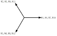
Fig. 3 (b) is the utility model embodiment two parts armature winding electromotive force star distribution map;
Fig. 3 (c) is the utility model embodiment two parts three phase winding combined electrical gesture star distribution maps.
Component symbol explanation among the figure:
The 1-rotating shaft, the 2-bearing, the 3-casing, the rotor core of 4-electro-magnetic flux switching motor, the stator core of 5-electro-magnetic flux switching motor, the stator core of 6-permagnetic synchronous motor, the 7-permanent magnet, the rotor core of 8-permagnetic synchronous motor, 9-armature winding, the 10-excitation winding, W1~W12-12 concentrated armature winding coil.
Embodiment
Below with reference to accompanying drawing, the technical solution of the utility model is elaborated.
As shown in Figure 1, the utility model provides a kind of block form composite excitation alternating current generator, comprise casing and be installed on casing interior 12/10 utmost point electro-magnetic flux switching motor and 24 grooves/20 pole permanent-magnet synchronous machines, electro-magnetic flux switching motor and permagnetic synchronous motor are installed in respectively the left and right sides in the same casing 3, wherein, the rotor core 4 of electro-magnetic flux switching motor and the rotor core 8 of permagnetic synchronous motor all are fixed in the rotating shaft 1, and respectively by bearing 2 supporting revolving shafts, permanent magnet 7 is installed in the rotor surface of permagnetic synchronous motor; The stator of electro-magnetic flux switching motor and permagnetic synchronous motor is installed in respectively the left and right sides of casing inside, excitation winding 10 is installed on the stator of electro-magnetic flux switching motor, the stator core 5 of electro-magnetic flux switching motor and the stator core of permagnetic synchronous motor 6 share a cover armature winding 9, and the every groove conductor element of two parts is directly connected.
In the utility model, 24 grooves/20 pole permanent-magnet synchronous machines adopt surface-mount type magnetic steel rotor structure or Interior permanent magnet rotor structure, and stator core is not for waiting facewidth structure, and wide tooth and narrow tooth are alternately distributed, on the wide tooth embedding around armature winding, on the narrow tooth not around armature winding; Its rotor adopts built-in tangential magnetic steel rotor structure or surface-mount type magnetic steel rotor structure, and stator core is formed by silicon steel plate stacking, shown in Fig. 2 (a).12/10 utmost point electro-magnetic flux switching motor stator is the salient pole stator of traditional flux switch motor, and wherein stator has 24 teeth, and the rotor number of teeth is 10, and the simultaneously embedding of armature winding and excitation winding is on the diverse location of stator tooth, shown in Fig. 2 (b).The armature winding phase sequence of described permagnetic synchronous motor and phase winding distribute identical with the armature winding of electro-magnetic flux switching motor, the simultaneously embedding of the every phase winding of the utility model alternating current generator is on the corresponding stator poles of permanent-magnetic synchronous motor stator tooth and electro-magnetic flux switching motor, through closed after the two-part stator core.
In order to realize the direct series connection of two parts winding, need the winding electromotive force star graph of explanation two parts motor, shown in Fig. 3 (a), be 24 grooves/20 pole permanent-magnet synchronous machines and 12 stator armature windings of 12/10 utmost point electro-magnetic flux switching motor mechanical angle position; In like manner, be depicted as 24 grooves/20 pole permanent-magnet synchronous machines and 12 stator armature windings of 12/10 utmost point electro-magnetic flux switching motor electromotive force star distribution map such as Fig. 3 (b), Fig. 3 (c) has provided the threephase armature winding combination electromotive force star distribution map of motor.
Above embodiment only is explanation technological thought of the present utility model; can not limit protection range of the present utility model with this; every technological thought according to the utility model proposes, any change of doing on the technical scheme basis all falls within the utility model protection range.
Claims (3)
1. block form composite excitation alternating current generator, it is characterized in that: comprise casing and be located at 24 interior grooves of casing/20 pole permanent-magnet synchronous machines and 12/10 utmost point electro-magnetic flux switching motor, wherein, electro-magnetic flux switching motor and permagnetic synchronous motor are installed in respectively the inner left and right sides of casing, the two rotor coaxial rotation; Permagnetic synchronous motor has identical winding distribution form with electro-magnetic flux switching motor, and the every groove conductor element of two parts is directly connected, and shares a cover armature winding.
2. a kind of block form composite excitation alternating current generator as claimed in claim 1, it is characterized in that: the stator core of described 24 grooves/20 pole permanent-magnet synchronous machines is not for waiting facewidth structure, wide tooth and narrow tooth are alternately distributed, embedding is around armature winding on the wide tooth, not around armature winding, rotor adopts surface-mount type magnetic steel structure or built-in magnetic steel construction on the narrow tooth; The stator of 12/10 utmost point electro-magnetic flux switching motor is the salient pole stator of flux switch motor, and excitation winding and armature winding all are installed on the stator, and rotor also is salient-pole structure.
3. a kind of block form composite excitation alternating current generator as claimed in claim 1, it is characterized in that: the every phase armature winding of described block form composite excitation alternating current generator passes permagnetic synchronous motor and electro-magnetic flux switching motor simultaneously, and two parts embedding is corresponding one by one around the stator tooth of armature winding/utmost point locus and phase sequence.
Priority Applications (1)
| Application Number | Priority Date | Filing Date | Title |
|---|---|---|---|
| CN 201220456807 CN202798389U (en) | 2012-09-07 | 2012-09-07 | Side-by-side mixing excitation alternating current generator |
Applications Claiming Priority (1)
| Application Number | Priority Date | Filing Date | Title |
|---|---|---|---|
| CN 201220456807 CN202798389U (en) | 2012-09-07 | 2012-09-07 | Side-by-side mixing excitation alternating current generator |
Publications (1)
| Publication Number | Publication Date |
|---|---|
| CN202798389U true CN202798389U (en) | 2013-03-13 |
Family
ID=47825562
Family Applications (1)
| Application Number | Title | Priority Date | Filing Date |
|---|---|---|---|
| CN 201220456807 Expired - Fee Related CN202798389U (en) | 2012-09-07 | 2012-09-07 | Side-by-side mixing excitation alternating current generator |
Country Status (1)
| Country | Link |
|---|---|
| CN (1) | CN202798389U (en) |
Cited By (3)
| Publication number | Priority date | Publication date | Assignee | Title |
|---|---|---|---|---|
| CN102843008A (en) * | 2012-09-07 | 2012-12-26 | 南京航空航天大学 | Parallel type mixed excitation alternating-current generator |
| CN108206595A (en) * | 2016-12-20 | 2018-06-26 | 郑州宇通客车股份有限公司 | A kind of permanent magnet motor stator and magneto |
| CN106787550B (en) * | 2017-02-03 | 2023-10-31 | 上海通凌化工有限公司 | Wide-voltage motor suitable for ecological balance instrument and control method |
-
2012
- 2012-09-07 CN CN 201220456807 patent/CN202798389U/en not_active Expired - Fee Related
Cited By (4)
| Publication number | Priority date | Publication date | Assignee | Title |
|---|---|---|---|---|
| CN102843008A (en) * | 2012-09-07 | 2012-12-26 | 南京航空航天大学 | Parallel type mixed excitation alternating-current generator |
| CN108206595A (en) * | 2016-12-20 | 2018-06-26 | 郑州宇通客车股份有限公司 | A kind of permanent magnet motor stator and magneto |
| CN108206595B (en) * | 2016-12-20 | 2023-08-11 | 宇通客车股份有限公司 | Permanent magnet motor |
| CN106787550B (en) * | 2017-02-03 | 2023-10-31 | 上海通凌化工有限公司 | Wide-voltage motor suitable for ecological balance instrument and control method |
Similar Documents
| Publication | Publication Date | Title |
|---|---|---|
| CN103208893B (en) | Induced excitation formula composite excitation brushless synchronous motor | |
| CN105449881B (en) | Low six phase doubly-salient brushless DC generator of mutual inductance error-tolerance type | |
| CN105048740B (en) | A kind of permanent magnetism and variable reluctance block form mixed excitation brushless | |
| CN101699713B (en) | Rotor sectional type flux switching motor and method for improving sine degree of back electromotive force thereof | |
| CN102290883B (en) | Redundant excitation double-armature winding multiphase magnetic flux switching motor with fault-tolerant teeth | |
| CN102035270B (en) | Axial excitation double salient pole motors | |
| CN101562383B (en) | Single-phase reluctance generator | |
| CN103248158A (en) | Six-phase flux switching type permanent magnet motor | |
| CN104201852A (en) | Winding-complementary permanent magnet rotor magnetic-flux switching motor | |
| CN102843008A (en) | Parallel type mixed excitation alternating-current generator | |
| CN102157993A (en) | Modularized flux switching permanent magnet (FSPM) motor | |
| CN103248148A (en) | Mixed excitation stator surface-mounted double-salient motor | |
| CN102005879B (en) | Electric excitation part double stator brushless mixed excitation synchronous generator | |
| CN201860217U (en) | Parallel-structured brushless composite-excitation synchronous motor without additional air gap | |
| CN102005875B (en) | Brushless parallel-structure hybrid excitation synchronous generator without additional air gap | |
| CN202798389U (en) | Side-by-side mixing excitation alternating current generator | |
| CN202889138U (en) | Parallel type composite excitation brushless direct-current motor | |
| CN102832767B (en) | Parallel hybrid excitation brushless direct-current fault-tolerant motor | |
| CN201188577Y (en) | Single-phase reluctance generator | |
| CN101478207B (en) | Dual feedback mixed magnetic pole permanent magnetic motor | |
| CN102403857A (en) | Stator surface-mounted doubly salient permanent-magnet motor with complementary winding magnetic paths | |
| CN104767336A (en) | Single-phase separately-excited magneto-resistive power generator | |
| CN201860232U (en) | Hybrid excitation synchronous generator in parallel structure without electric excitation rotor | |
| CN106100272A (en) | The double-salient-pole magnetic flux controllable motor that a kind of few rare earth tooth yoke is complementary | |
| CN102611219A (en) | High-reliability half stator-tooth winded stator-surface mounted permanent magnet motor |
Legal Events
| Date | Code | Title | Description |
|---|---|---|---|
| C14 | Grant of patent or utility model | ||
| GR01 | Patent grant | ||
| CF01 | Termination of patent right due to non-payment of annual fee |
Granted publication date: 20130313 Termination date: 20160907 |
|
| CF01 | Termination of patent right due to non-payment of annual fee |