CN202796540U - Fluorescent switch sleeve - Google Patents
Fluorescent switch sleeve Download PDFInfo
- Publication number
- CN202796540U CN202796540U CN 201220472251 CN201220472251U CN202796540U CN 202796540 U CN202796540 U CN 202796540U CN 201220472251 CN201220472251 CN 201220472251 CN 201220472251 U CN201220472251 U CN 201220472251U CN 202796540 U CN202796540 U CN 202796540U
- Authority
- CN
- China
- Prior art keywords
- panel
- hole
- switch cover
- square hole
- fluorescent
- Prior art date
- Legal status (The legal status is an assumption and is not a legal conclusion. Google has not performed a legal analysis and makes no representation as to the accuracy of the status listed.)
- Expired - Fee Related
Links
- 238000004519 manufacturing process Methods 0.000 abstract description 4
- 238000011835 investigation Methods 0.000 abstract 1
- 238000000465 moulding Methods 0.000 abstract 1
- 238000009434 installation Methods 0.000 description 4
- 230000009286 beneficial effect Effects 0.000 description 2
- 238000010586 diagram Methods 0.000 description 1
- 238000000034 method Methods 0.000 description 1
Images

Landscapes
- Push-Button Switches (AREA)
Abstract
Description
技术领域 technical field
本实用新型涉及一种荧光开关套。 The utility model relates to a fluorescent switch cover.
背景技术 Background technique
目前市场上的发光开关套主要是家用住宅中安装的电源开关套,为了在晚上便于使用,通常在开关按钮上图上荧光材料或者贴上萤光片,但是由于开关经常使用,会造成荧光材料的脱落,影响整体外观。 At present, the luminous switch cover on the market is mainly the power switch cover installed in the home. In order to facilitate use at night, fluorescent materials or fluorescent sheets are usually placed on the switch button, but because the switch is often used, it will cause fluorescent material The peeling off affects the overall appearance.
发明内容 Contents of the invention
本实用新型要解决的技术问题是提供一种美观实用,制造成本低,且安装方便的荧光开关套。 The technical problem to be solved by the utility model is to provide a fluorescent switch cover which is beautiful and practical, has low manufacturing cost and is easy to install.
为解决上述问题,本实用新型采用如下技术方案:一种荧光开关套,包括上面板,及设置在上面板下端的下面板,所述上面板表面设有荧光层,所述上面板设有第一通孔,所述上面板中间设有第一方孔,所述下面板设有第二通孔,所述下面板中间设有第二方孔,所述下面板底部设有绝缘层。 In order to solve the above problems, the utility model adopts the following technical scheme: a fluorescent switch cover, including an upper panel, and a lower panel arranged at the lower end of the upper panel, the surface of the upper panel is provided with a fluorescent layer, and the upper panel is provided with a second panel. A through hole, a first square hole is provided in the middle of the upper panel, a second through hole is provided in the lower panel, a second square hole is provided in the middle of the lower panel, and an insulating layer is provided at the bottom of the lower panel.
作为优选,所述上面板上的第一通孔和下面板上的第二通孔均设有多个,且第一通孔和第二通孔内部均设有螺纹。 Preferably, there are multiple first through holes on the upper panel and multiple second through holes on the lower panel, and threads are provided inside the first through holes and the second through holes.
作为优选,所述上面板通过螺钉固定在下面板上,所述下面板通过螺钉固定在墙面上。 Preferably, the upper panel is fixed to the lower panel by screws, and the lower panel is fixed to the wall by screws.
本实用新型的有益效果是:将开关套主体分为了上、下两个部分,通过上面板和下面板中间开设的第一方孔和第二方孔,可以配合不同尺寸的开关,安装极为的方便,开关套上面板设置的荧光层可以在夜间发出荧光,使用者通过荧光可以轻易的找到开关,不必再盲目的摸索,开关套下面板设有绝缘层,防止了漏电事故的发生,且造型十分美观,制造成本低,安装极为方便,适合在日常生活中推广使用。 The beneficial effect of the utility model is: the main body of the switch cover is divided into upper and lower parts, through the first square hole and the second square hole opened in the middle of the upper panel and the lower panel, it can be matched with switches of different sizes, and the installation is extremely easy. Convenient, the fluorescent layer set on the upper panel of the switch cover can emit fluorescence at night, the user can easily find the switch through the fluorescent light, no need to blindly grope, the lower panel of the switch cover is provided with an insulating layer, which prevents the occurrence of electric leakage accidents, and the shape Very beautiful, low manufacturing cost, very convenient installation, suitable for popularization and use in daily life.
附图说明 Description of drawings
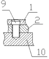
图1为本实用新型荧光开关套的结构示意图; Fig. 1 is the structural representation of the utility model fluorescent switch cover;
图2为本实用新型荧光开关套的螺纹连接示意图。 Fig. 2 is a schematic diagram of the screw connection of the fluorescent switch sleeve of the present invention.
具体实施方式 Detailed ways
如图1和图2所示的一种荧光开关套,包括上面板1,及设置在上面板1下端的下面板2,所述上面板1表面设有荧光层3,所述上面板1设有第一通孔4,所述上面板1中间设有第一方孔5,所述下面板2设有第二通孔6,所述下面板2中间设有第二方孔7,所述下面板2底部设有绝缘层8。
A kind of fluorescent switch cover as shown in Figure 1 and Figure 2, comprises
其中,所述上面板1上的第一通孔4和下面板2上的第二通孔6均设有多个,且第一通孔4和第二通孔6内部均设有螺纹,所述上面板1通过螺钉9固定在下面板2上,所述下面板2通过螺钉固定在墙面10上。
Wherein, the first through
本实用新型的有益效果是:将开关套主体分为了上、下两个部分,通过上面板和下面板中间开设的第一方孔和第二方孔,可以配合不同尺寸的开关,安装极为的方便,开关套上面板设置的荧光层可以在夜间发出荧光,使用者通过荧光可以轻易的找到开关,不必再盲目的摸索,开关套下面板设有绝缘层,防止了漏电事故的发生,且造型十分美观,制造成本低,安装极为方便,适合在日常生活中推广使用。 The beneficial effect of the utility model is: the main body of the switch cover is divided into upper and lower parts, through the first square hole and the second square hole opened in the middle of the upper panel and the lower panel, it can be matched with switches of different sizes, and the installation is extremely easy. Convenient, the fluorescent layer set on the upper panel of the switch cover can emit fluorescence at night, the user can easily find the switch through the fluorescent light, no need to blindly grope, the lower panel of the switch cover is provided with an insulating layer, which prevents the occurrence of electric leakage accidents, and the shape Very beautiful, low manufacturing cost, very convenient installation, suitable for popularization and use in daily life.
以上所述,仅为本实用新型的具体实施方式,但本实用新型的保护范围并不局限于此,任何不经过创造性劳动想到的变化或替换,都应涵盖在本实用新型的保护范围之内。因此,本实用新型的保护范围应该以权利要求书所限定的保护范围为准。 The above is only a specific embodiment of the utility model, but the scope of protection of the utility model is not limited thereto, and any change or replacement that is not thought of through creative work should be covered within the scope of protection of the utility model . Therefore, the protection scope of the present utility model should be determined by the protection scope defined in the claims.
Claims (3)
Priority Applications (1)
| Application Number | Priority Date | Filing Date | Title |
|---|---|---|---|
| CN 201220472251 CN202796540U (en) | 2012-09-17 | 2012-09-17 | Fluorescent switch sleeve |
Applications Claiming Priority (1)
| Application Number | Priority Date | Filing Date | Title |
|---|---|---|---|
| CN 201220472251 CN202796540U (en) | 2012-09-17 | 2012-09-17 | Fluorescent switch sleeve |
Publications (1)
| Publication Number | Publication Date |
|---|---|
| CN202796540U true CN202796540U (en) | 2013-03-13 |
Family
ID=47823750
Family Applications (1)
| Application Number | Title | Priority Date | Filing Date |
|---|---|---|---|
| CN 201220472251 Expired - Fee Related CN202796540U (en) | 2012-09-17 | 2012-09-17 | Fluorescent switch sleeve |
Country Status (1)
| Country | Link |
|---|---|
| CN (1) | CN202796540U (en) |
-
2012
- 2012-09-17 CN CN 201220472251 patent/CN202796540U/en not_active Expired - Fee Related
Similar Documents
| Publication | Publication Date | Title |
|---|---|---|
| CN204201610U (en) | Multi-function desk lamp | |
| CN203178683U (en) | Multifunctional solar electronic clock | |
| CN202266895U (en) | Timing candle | |
| CN205383533U (en) | A solar lawn lamp | |
| CN204477845U (en) | New indoor flat lamp | |
| CN203236952U (en) | Inductive colored lamp mural | |
| CN204227277U (en) | A kind of ceiling lamp | |
| CN204345486U (en) | A kind of separate assembling LED illumination lamp | |
| CN202118659U (en) | Desk lamp with function of tissue box | |
| CN202992838U (en) | Light-emitting diode (LED) energy saving lamp | |
| CN204100088U (en) | A kind of LED lamp | |
| CN203841397U (en) | Bed with intelligent lighting system | |
| CN201303319Y (en) | A touch screen wall switch | |
| CN202253089U (en) | Desk lamp | |
| CN202834973U (en) | Desk lamp with touch switch | |
| CN201900919U (en) | Novel pen container | |
| CN203215394U (en) | Creative light-emitting diode (LED) vase lamp | |
| CN202796533U (en) | A point type glass wall switch | |
| CN201902977U (en) | Solar LED (light emitting diode) garden lamp | |
| CN202452359U (en) | Solar lamp | |
| CN201340654Y (en) | Noctilucent remote controller | |
| CN204492339U (en) | A kind of touch door handle | |
| CN203431572U (en) | LED light wall | |
| CN205782558U (en) | A kind of solar energy garden lamp | |
| CN202532361U (en) | Multi-functional desk lamp |
Legal Events
| Date | Code | Title | Description |
|---|---|---|---|
| C14 | Grant of patent or utility model | ||
| GR01 | Patent grant | ||
| C17 | Cessation of patent right | ||
| CF01 | Termination of patent right due to non-payment of annual fee |
Granted publication date: 20130313 Termination date: 20130917 |