CN202779877U - Automatic positioning frame - Google Patents
Automatic positioning frame Download PDFInfo
- Publication number
- CN202779877U CN202779877U CN 201220343104 CN201220343104U CN202779877U CN 202779877 U CN202779877 U CN 202779877U CN 201220343104 CN201220343104 CN 201220343104 CN 201220343104 U CN201220343104 U CN 201220343104U CN 202779877 U CN202779877 U CN 202779877U
- Authority
- CN
- China
- Prior art keywords
- gear
- jaw
- positioning frame
- automatic positioning
- clamping disc
- Prior art date
- Legal status (The legal status is an assumption and is not a legal conclusion. Google has not performed a legal analysis and makes no representation as to the accuracy of the status listed.)
- Expired - Fee Related
Links
Images
Abstract
The utility model discloses an automatic positioning frame which comprises a three-jaw clamping disc, a gear connection rod, a gear, a straight rack and an adjustable air cylinder. The adjustable air cylinder is fixed at the top of the straight rack, the bottom of the straight rack is meshed with the gear which is connected with the three-jaw clamping disc through the gear connection rod, a clamping disc jaw is mounted on one side of the three-jaw clamping disc, bearings are mounted on an inner side of the clamping disc jaw, an oil box and a supporting rod are arranged on one side of the adjustable air cylinder, and the supporting rod is perpendicular to the surface of the adjustable air cylinder. The automatic positioning frame is simple in structure, convenient, practical, capable of guaranteeing that the concentricity during product processing is within 0.02mm, adjustable in space of the bearings and applicable to various products with different diameters.
Description
Technical field
The utility model belongs to the mechanical processing and positioning field, is specifically related to a kind of automatic positioning frame.
Background technology
Lathe is the important working equipment of mechanical field at present, and the lathe kind is many, there are some specially elongated round condition to be done Surface Machining, comprise instrument lathe, automatic instrument lathe and CNC automatic turning machine etc., all be more common at this class lathe locating rack that uses to the fixing of product now, cause in process, product is because rotation has a centrifugal action, product can rock, cause concentricity larger, affect product quality, and these lathes all can only process the product of fixed diameter, application is very little.
Summary of the invention
Technical problem to be solved in the utility model is for above-mentioned the deficiencies in the prior art, provides a kind of concentricity little, the lathe locating rack that the product diameter range of processing is larger.
The technical scheme that the utility model adopts is: a kind of automatic positioning frame, comprise scroll chuck, gear connecting rod, gear, spur rack, adjustable cylinder, adjustable cylinder is fixed on the top of spur rack, the bottom of spur rack and gear engagement, gear is connected with scroll chuck by gear connecting rod, and a side of described scroll chuck is equipped with chuck jaw, and bearing is equipped with in the inboard of chuck jaw, one side of described adjustable cylinder is provided with an oil box and a pole, the Surface Vertical of described pole and adjustable cylinder.
As preferably, described pole is a telescopic structure.
The beneficial effects of the utility model are: the utility model is simple in structure, convenient and practical, can guarantee that product adds the concentricity in man-hour and reaches in 0.02 millimeter, and can regulate the spacing of bearing, so that can be applied on the product of multiple different-diameter; Be provided with pole, be convenient to after spur rack and cylinder damage, utilize pole to take out spur rack, then it is placed under repair, be provided with oil box, can be oily to gear, spur rack etc. at any time, so that the utility model is better maintained, prolong its service life.
Description of drawings
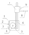
Fig. 1 is structural representation of the present utility model.
Among the figure: 1, scroll chuck; 2, bearing; 3, chuck jaw; 4, gear connecting rod; 5, gear; 6, spur rack; 7, adjustable cylinder; 8, pole; 9, oil box.
The specific embodiment
Below in conjunction with the accompanying drawings and the specific embodiments the utility model is described in further detail.
Embodiment: as shown in Figure 1, the utility model comprises scroll chuck 1, gear connecting rod 4, gear 5, spur rack 6, adjustable cylinder 7, adjustable cylinder 7 is fixed on the top of spur rack 6, the bottom of spur rack 6 and gear 5 engagements, gear 5 is connected with scroll chuck 1 by gear connecting rod 4, one side of described scroll chuck 1 is equipped with chuck jaw 3, bearing 2 is equipped with in the inboard of chuck jaw 3, one side of described adjustable cylinder 7 is provided with an oil box 9 and a pole 8, described pole 8 is a telescopic structure, and with the Surface Vertical of adjustable cylinder 7.
During use, when adjustable cylinder 7 was supplied with air pressure by air pump, adjustable cylinder 7 pressed down, and drove spur rack 6 and moved down, and by engagement, driven gear 5 rotates, and gear connecting rod 4 also rotates simultaneously, thus the spacing between control scroll chuck 1 upper bearing (metal) 2.
Claims (2)
1. automatic positioning frame, comprise scroll chuck, gear connecting rod, gear, spur rack, adjustable cylinder, it is characterized in that: adjustable cylinder is fixed on the top of spur rack, the bottom of spur rack and gear engagement, gear is connected with scroll chuck by gear connecting rod, and a side of described scroll chuck is equipped with chuck jaw, and bearing is equipped with in the inboard of chuck jaw, one side of described adjustable cylinder is provided with an oil box and a pole, the Surface Vertical of described pole and adjustable cylinder.
2. automatic positioning frame according to claim 1, it is characterized in that: described pole is a telescopic structure.
Priority Applications (1)
| Application Number | Priority Date | Filing Date | Title |
|---|---|---|---|
| CN 201220343104 CN202779877U (en) | 2012-07-16 | 2012-07-16 | Automatic positioning frame |
Applications Claiming Priority (1)
| Application Number | Priority Date | Filing Date | Title |
|---|---|---|---|
| CN 201220343104 CN202779877U (en) | 2012-07-16 | 2012-07-16 | Automatic positioning frame |
Publications (1)
| Publication Number | Publication Date |
|---|---|
| CN202779877U true CN202779877U (en) | 2013-03-13 |
Family
ID=47807219
Family Applications (1)
| Application Number | Title | Priority Date | Filing Date |
|---|---|---|---|
| CN 201220343104 Expired - Fee Related CN202779877U (en) | 2012-07-16 | 2012-07-16 | Automatic positioning frame |
Country Status (1)
| Country | Link |
|---|---|
| CN (1) | CN202779877U (en) |
-
2012
- 2012-07-16 CN CN 201220343104 patent/CN202779877U/en not_active Expired - Fee Related
Similar Documents
| Publication | Publication Date | Title |
|---|---|---|
| CN201632679U (en) | Multi-station drilling and tapping machine | |
| CN204353523U (en) | The compound porous drilling machine of a kind of disc | |
| CN203265801U (en) | Gear hobbing machine | |
| CN105033794A (en) | Double-end inner-hole grinding machine | |
| CN204868389U (en) | Double -end hole grinding machine | |
| CN202684537U (en) | Automatic positioning frame | |
| CN202779877U (en) | Automatic positioning frame | |
| CN204075285U (en) | A kind of fixture for boring machine of taper hole on processing parts | |
| CN203019110U (en) | Adjustable carrier roller of long shaft workpieces | |
| CN203019216U (en) | Gantry type polishing machine support system | |
| CN202278362U (en) | Assembling tool of adjustable shaft workpiece | |
| CN203437682U (en) | Double-drill-bit horizontal drilling machine | |
| CN202639376U (en) | Automatic positioning frame | |
| CN204248022U (en) | End face drilling machine | |
| CN204912833U (en) | Take automatic drilling machine of drill bit location | |
| CN203779098U (en) | Vertical processing machine tool for processing cylindrical valve of water turbine | |
| CN204770716U (en) | Static pressure tailstock structure | |
| CN203610713U (en) | Simple radial drilling machine with high efficiency | |
| CN202702070U (en) | Simple divider | |
| CN203390267U (en) | Milling machine with rotary worktable | |
| CN202922049U (en) | Manually-operated drilling machine positioning table special for automobile hub and manually-operated tapping drilling machine | |
| CN202668208U (en) | Adjustable porous drilling and clamping device | |
| CN202377626U (en) | Wire cutting machine tool and coil holder head of same | |
| CN201693370U (en) | Vertical lathe workbench | |
| CN202622376U (en) | Automatic locating rack |
Legal Events
| Date | Code | Title | Description |
|---|---|---|---|
| C14 | Grant of patent or utility model | ||
| GR01 | Patent grant | ||
| C17 | Cessation of patent right | ||
| CF01 | Termination of patent right due to non-payment of annual fee |
Granted publication date: 20130313 Termination date: 20130716 |