CN202768278U - Self-steering wind driven generator - Google Patents
Self-steering wind driven generator Download PDFInfo
- Publication number
- CN202768278U CN202768278U CN2012205597706U CN201220559770U CN202768278U CN 202768278 U CN202768278 U CN 202768278U CN 2012205597706 U CN2012205597706 U CN 2012205597706U CN 201220559770 U CN201220559770 U CN 201220559770U CN 202768278 U CN202768278 U CN 202768278U
- Authority
- CN
- China
- Prior art keywords
- stator
- rotor
- nacelle
- wind
- self
- Prior art date
- Legal status (The legal status is an assumption and is not a legal conclusion. Google has not performed a legal analysis and makes no representation as to the accuracy of the status listed.)
- Expired - Fee Related
Links
Classifications
-
- Y—GENERAL TAGGING OF NEW TECHNOLOGICAL DEVELOPMENTS; GENERAL TAGGING OF CROSS-SECTIONAL TECHNOLOGIES SPANNING OVER SEVERAL SECTIONS OF THE IPC; TECHNICAL SUBJECTS COVERED BY FORMER USPC CROSS-REFERENCE ART COLLECTIONS [XRACs] AND DIGESTS
- Y02—TECHNOLOGIES OR APPLICATIONS FOR MITIGATION OR ADAPTATION AGAINST CLIMATE CHANGE
- Y02E—REDUCTION OF GREENHOUSE GAS [GHG] EMISSIONS, RELATED TO ENERGY GENERATION, TRANSMISSION OR DISTRIBUTION
- Y02E10/00—Energy generation through renewable energy sources
- Y02E10/70—Wind energy
- Y02E10/72—Wind turbines with rotation axis in wind direction
Landscapes
- Connection Of Motors, Electrical Generators, Mechanical Devices, And The Like (AREA)
- Wind Motors (AREA)
Abstract
本实用新型涉及发电机领域,尤其涉及一种风力发电机。一种自转向风力发电机,所述机舱通过铰接轴安装在塔架上,所述转子铰接在机舱内,所述定子罩在转子外,定子与机舱内壁固定相连,定子与转子之间有一定间隙同轴设置,转子的轴心处固定装有转轴,所述叶片共有若干个周向均布固定安装在转轴上,所述机舱外还装有风向测量装置和驱动风扇,机舱内还有控制器和离合器,所述驱动风扇通过离合器驱动连接塔架与机舱之间的铰接轴,所述风向测量装置的输出端与控制器相连,所述控制器控制连接离合器。本实用新型通过风向测量装置测得风向后,由控制器觉得是否调整机舱朝向;机舱的运动由风力驱动的风扇带动,无需使用电力,提高了风力发电机的发电效率。
The utility model relates to the field of generators, in particular to a wind power generator. A self-steering wind power generator, the nacelle is installed on the tower through a hinge shaft, the rotor is hinged in the nacelle, the stator cover is outside the rotor, the stator is fixedly connected to the inner wall of the nacelle, and there is a certain gap between the stator and the rotor. The gap is coaxially arranged, and the shaft center of the rotor is fixedly equipped with a rotating shaft. The blades are fixed and installed on the rotating shaft in a total of several circumferential uniform distributions. The wind direction measuring device and the driving fan are installed outside the cabin, and there are also a controller and a fan in the cabin. The clutch is used to drive the fan to connect the articulated shaft between the tower and the nacelle, the output end of the wind direction measuring device is connected to the controller, and the controller controls the connection of the clutch. In the utility model, after the wind direction is measured by the wind direction measuring device, the controller determines whether to adjust the orientation of the nacelle; the movement of the nacelle is driven by a fan driven by the wind, without using electric power, and the power generation efficiency of the wind power generator is improved.
Description
技术领域 technical field
本实用新型涉及发电机领域,尤其涉及一种风力发电机。The utility model relates to the field of generators, in particular to a wind power generator.
背景技术 Background technique
是将风能转换为机械功的动力机械,又称风车。广义地说,它是一种以太阳为热源,以大气为工作介质的热能利用发动机。风力发电利用的是自然能源。It is a power machine that converts wind energy into mechanical work, also known as a windmill. Broadly speaking, it is a thermal energy utilization engine that uses the sun as the heat source and the atmosphere as the working medium. Wind power utilizes natural energy.
风力发电的原理,是利用风力带动风车叶片旋转,再透过增速机将旋转的速度提升,来促使发电机发电。依据目前的风车技术,大约是每秒三公尺的微风速度,便可以开始发电。风力发电正在世界上形成一股热潮,因为风力发电没有燃料问题,也不会产生辐射或空气污染。风力发电在芬兰、丹麦等国家很流行;我国也在西部地区大力提倡。The principle of wind power generation is to use the wind to drive the blades of the windmill to rotate, and then increase the speed of rotation through the speed increaser to drive the generator to generate electricity. According to the current windmill technology, electricity can be generated at a breeze speed of about three meters per second. Wind power is becoming a craze around the world because it has no fuel issues and doesn't produce radiation or air pollution. Wind power is very popular in Finland, Denmark and other countries; my country is also vigorously promoting it in the western region.
现有的风力发电机主要由机头、转体、尾翼、叶片组成。每一部分都很重要,各部分功能为:叶片用来接受风力并通过机头转为电能;尾翼使叶片始终对着来风的方向从而获得最大的风能;转体能使机头灵活地转动以实现尾翼调整方向的功能;机头的转子是永磁体,定子绕组切割磁力线产生电能。风力发电机因风向不稳定,所以需要根据来风方向不断转向,现有的风力发电机的转向都是利用一个独立的电机驱动机头转动,需要额外的动力源,降低了发电效率。Existing wind generators are mainly composed of nose, swivel, empennage and blades. Every part is very important, and the functions of each part are: the blades are used to receive wind force and convert it into electrical energy through the nose; the empennage makes the blades always face the direction of the wind to obtain the maximum wind energy; The function of the empennage to adjust the direction; the rotor of the nose is a permanent magnet, and the stator winding cuts the magnetic field lines to generate electric energy. Due to the unstable wind direction, the wind generator needs to continuously turn according to the direction of the wind. The steering of the existing wind generator is driven by an independent motor to rotate the nose, which requires an additional power source and reduces the power generation efficiency.
发明内容 Contents of the invention
本实用新型所要解决的技术问题是提供一种自转向风力发电机,该风力发电机通过风向测量装置测得风向后,由控制器觉得是否调整机舱朝向;机舱的运动由风力驱动的风扇带动,无需使用电力,提高了风力发电机的发电效率。The technical problem to be solved by the utility model is to provide a self-steering wind generator. After the wind generator measures the wind direction through the wind direction measuring device, the controller determines whether to adjust the orientation of the cabin; the movement of the cabin is driven by a fan driven by wind, It does not need to use electricity, which improves the power generation efficiency of the wind turbine.
本实用新型是这样实现的:一种自转向风力发电机,包括塔架、机舱、定子、转子和叶片,所述机舱通过铰接轴安装在塔架上,所述转子铰接在机舱内,所述定子罩在转子外,定子与机舱内壁固定相连,定子与转子之间有一定间隙同轴设置,转子的轴心处固定装有转轴,所述叶片共有若干个周向均布固定安装在转轴上,所述机舱外还装有风向测量装置和驱动风扇,机舱内还有控制器和离合器,所述驱动风扇通过离合器驱动连接塔架与机舱之间的铰接轴,所述风向测量装置的输出端与控制器相连,所述控制器控制连接离合器。The utility model is realized in the following way: a self-steering wind power generator comprises a tower frame, a nacelle, a stator, a rotor and blades, the nacelle is installed on the tower frame through a hinged shaft, the rotor is hinged in the nacelle, the The stator is covered outside the rotor, and the stator is fixedly connected to the inner wall of the nacelle. There is a certain gap between the stator and the rotor and is coaxially arranged. The shaft center of the rotor is fixedly equipped with a rotating shaft. A wind direction measuring device and a driving fan are also installed outside the nacelle, and a controller and a clutch are also arranged in the nacelle, and the driving fan is driven to connect the articulated shaft between the tower and the nacelle through the clutch, and the output end of the wind direction measuring device is connected to the control The controller is connected, and the controller controls to connect the clutch.
所述离合器与铰接轴之间还设置有变速箱。A gearbox is also arranged between the clutch and the hinge shaft.
所述的定子包括定子机架、定子铁芯和定子绕组,所述定子机架通过机座固定安装在机舱内,所述的定子铁芯为环形铁芯,定子铁芯固定安装在定子机架上,所述定子绕组镶在定子铁芯上。The stator includes a stator frame, a stator core and a stator winding. The stator frame is fixedly installed in the nacelle through a machine base. The stator core is an annular iron core, and the stator core is fixedly installed on the stator frame. Above, the stator winding is set on the stator core.
所述的转子包括转子机架、转子磁轭和永磁极,所述转子机架固定安装在转轴上,转轴通过机座铰接在机舱内,所述转子磁轭和永磁极都为环形,转子磁轭固定套装在转子机架外,永磁极固定套装在转子磁轭外。The rotor includes a rotor frame, a rotor yoke and permanent magnet poles, the rotor frame is fixedly installed on the rotating shaft, and the rotating shaft is hinged in the nacelle through the frame, the rotor yoke and the permanent magnet poles are ring-shaped, and the rotor magnet The yoke is fixedly set outside the rotor frame, and the permanent magnet pole is fixedly set outside the rotor yoke.
所述的若干个叶通过轮毂周向均布固定安装在转轴上。The several blades are uniformly distributed in the circumferential direction of the hub and fixedly installed on the rotating shaft.
本实用新型自转向风力发电机通过风向测量装置测得风向后,由控制器觉得是否调整机舱朝向;机舱的运动由风力驱动的风扇带动,无需使用电力,提高了风力发电机的发电效率。After the self-steering wind generator of the utility model measures the wind direction through the wind direction measuring device, the controller determines whether to adjust the orientation of the nacelle; the movement of the nacelle is driven by a fan driven by wind, without using electric power, and the power generation efficiency of the wind generator is improved.
附图说明 Description of drawings
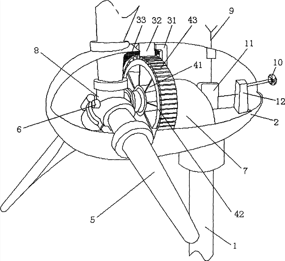
图1为本实用新型自转向风力发电机结构示意图。Fig. 1 is a structural schematic diagram of the utility model self-steering wind power generator.
图中:1塔架、2机舱、31定子机架、32定子铁芯、33定子绕组、41转子机架、42转子磁轭、43永磁极、5叶片、6转轴、7机座、8轮毂、9风向测量装置、10驱动风扇、11控制器、12离合器。In the figure: 1 tower, 2 engine room, 31 stator frame, 32 stator core, 33 stator winding, 41 rotor frame, 42 rotor yoke, 43 permanent magnetic pole, 5 blades, 6 rotating shaft, 7 base, 8 hub , 9 wind direction measuring device, 10 drive fan, 11 controller, 12 clutch.
具体实施方式 Detailed ways
下面结合具体实施例,进一步阐述本实用新型。应理解,这些实施例仅用于说明本实用新型而不用于限制本实用新型的范围。此外应理解,在阅读了本实用新型表述的内容之后,本领域技术人员可以对本实用新型作各种改动或修改,这些等价形式同样落于本申请所附权利要求书所限定的范围。Below in conjunction with specific embodiment, further set forth the utility model. It should be understood that these embodiments are only used to illustrate the present utility model and are not intended to limit the scope of the present utility model. In addition, it should be understood that after reading the content of the utility model, those skilled in the art can make various changes or modifications to the utility model, and these equivalent forms also fall within the scope defined by the appended claims of the application.
实施例1Example 1
如图1所示,种自转向风力发电机,包括塔架1、机舱2、定子、转子和叶片5,所述机舱2通过铰接轴安装在塔架1上,所述转子铰接在机舱内,所述定子罩在转子外,定子与机舱2内壁固定相连,定子与转子之间有一定间隙同轴设置,转子的轴心处固定装有转轴6,所述叶片5共有若干个周向均布固定安装在转轴6上,所述机舱2外还装有风向测量装置9和驱动风扇10,机舱2内还有控制器11和离合器12,所述驱动风扇10通过离合器12驱动连接塔架1与机舱2之间的铰接轴,所述风向测量装置9的输出端与控制器11相连,所述控制器11控制连接离合器12。As shown in Figure 1, a self-steering wind generator comprises a tower 1, a nacelle 2, a stator, a rotor and blades 5, the nacelle 2 is mounted on the tower 1 through a hinge shaft, and the rotor is hinged in the nacelle, The stator cover is outside the rotor, and the stator is fixedly connected to the inner wall of the nacelle 2. There is a certain gap between the stator and the rotor and is arranged coaxially. On the rotating shaft 6, a wind direction measuring device 9 and a driving fan 10 are installed outside the nacelle 2, and a controller 11 and a clutch 12 are also arranged in the nacelle 2, and the driving fan 10 is driven to connect the tower 1 and the nacelle 2 through the clutch 12. The output end of the wind direction measuring device 9 is connected to the controller 11 , and the controller 11 controls the connection of the clutch 12 .
为了能使得驱动风扇10能够顺利带动机舱2转动,所述离合器12与铰接轴之间还设置有变速箱。In order to enable the driving fan 10 to smoothly drive the nacelle 2 to rotate, a gearbox is also arranged between the clutch 12 and the hinge shaft.
本实用新型可以进一步描述为,所述的定子包括定子机架31、定子铁芯32和定子绕组33,所述定子机架31通过机座7固定安装在机舱2内,所述的定子铁芯32为环形铁芯,定子铁芯32固定安装在定子机架31上,所述定子绕组33镶在定子铁芯32上。The utility model can be further described as, the stator includes a stator frame 31, a stator core 32 and a stator winding 33, and the stator frame 31 is fixedly installed in the nacelle 2 through the frame 7, and the stator core 32 is an annular iron core, the stator iron core 32 is fixedly installed on the stator frame 31 , and the stator winding 33 is embedded on the stator iron core 32 .
本实用新型可以进一步描述为,所述的转子包括转子机架41、转子磁轭42和永磁极43,所述转子机架41固定安装在转轴6上,转轴6通过机座7铰接在机舱2内,所述转子磁轭42和永磁极43都为环形,转子磁轭42固定套装在转子机架41外,永磁极43固定套装在子磁轭42外。The utility model can be further described as, the rotor includes a rotor frame 41, a rotor yoke 42 and a permanent magnet pole 43, the rotor frame 41 is fixedly mounted on the rotating shaft 6, and the rotating shaft 6 is hinged to the nacelle 2 through the frame 7 Inside, the rotor yoke 42 and the permanent magnet pole 43 are ring-shaped, the rotor yoke 42 is fixedly set outside the rotor frame 41 , and the permanent magnet pole 43 is fixedly set outside the sub-yoke 42 .
在本实施例中,为了能使的叶片5技能牢固的安装在转轴6上,又能方便拆装和检修,所述的若干个叶片5通过轮毂8周向均布固定安装在转轴6上。In this embodiment, in order to securely install the blades 5 on the rotating shaft 6 and facilitate disassembly and maintenance, the plurality of blades 5 are uniformly distributed and fixed on the rotating shaft 6 through the hub 8 in the circumferential direction.
发电时通过风向测量装置9测得风向适合叶片5转动发电时,控制器11控制离合器12断开,驱动风扇10在风力下空转,机舱2不会调整方向;当风向测量装置9测得风向不适合叶片5转动发电时,控制器11控制离合器12合上,驱动风扇10在风力下旋转带动机舱2转动调整方向,提高发电效率。When generating electricity, the wind direction measured by the wind direction measuring device 9 is suitable for the blade 5 to rotate for power generation, the controller 11 controls the clutch 12 to disconnect, and the fan 10 is driven to idle under the wind force, and the nacelle 2 will not adjust the direction; When the blade 5 rotates to generate electricity, the controller 11 controls the clutch 12 to close, and the fan 10 is driven to rotate under the wind to drive the nacelle 2 to rotate and adjust the direction to improve the power generation efficiency.
Claims (5)
Priority Applications (1)
| Application Number | Priority Date | Filing Date | Title |
|---|---|---|---|
| CN2012205597706U CN202768278U (en) | 2012-10-09 | 2012-10-09 | Self-steering wind driven generator |
Applications Claiming Priority (1)
| Application Number | Priority Date | Filing Date | Title |
|---|---|---|---|
| CN2012205597706U CN202768278U (en) | 2012-10-09 | 2012-10-09 | Self-steering wind driven generator |
Publications (1)
| Publication Number | Publication Date |
|---|---|
| CN202768278U true CN202768278U (en) | 2013-03-06 |
Family
ID=47774859
Family Applications (1)
| Application Number | Title | Priority Date | Filing Date |
|---|---|---|---|
| CN2012205597706U Expired - Fee Related CN202768278U (en) | 2012-10-09 | 2012-10-09 | Self-steering wind driven generator |
Country Status (1)
| Country | Link |
|---|---|
| CN (1) | CN202768278U (en) |
Cited By (1)
| Publication number | Priority date | Publication date | Assignee | Title |
|---|---|---|---|---|
| CN108019318A (en) * | 2017-11-30 | 2018-05-11 | 无锡市天运五金机电有限公司 | A kind of wind generator device |
-
2012
- 2012-10-09 CN CN2012205597706U patent/CN202768278U/en not_active Expired - Fee Related
Cited By (1)
| Publication number | Priority date | Publication date | Assignee | Title |
|---|---|---|---|---|
| CN108019318A (en) * | 2017-11-30 | 2018-05-11 | 无锡市天运五金机电有限公司 | A kind of wind generator device |
Similar Documents
| Publication | Publication Date | Title |
|---|---|---|
| CN101017998A (en) | Directly driving mixed excitation dual stator wind power dynamotor | |
| CN101752968A (en) | Internally air-cooled dual-rotor generator | |
| CN202768275U (en) | Bird repellent wind driven generator | |
| CN207229300U (en) | High-power wind power generation system | |
| CN201142613Y (en) | A cooling rib direct drive permanent magnet synchronous single bearing wind turbine | |
| CN202326021U (en) | Two-way air duct type magnetic suspension wind power generation device | |
| CN202768276U (en) | Hurricane-proof wind-driven generator | |
| CN202228266U (en) | Wind collection type wind generating set | |
| CN202768279U (en) | Wind-driven generator with deflecting plate | |
| CN109695542A (en) | A kind of high-efficiency double-rotor wind power generating set | |
| CN2767696Y (en) | Double-rotor wind-driven generator | |
| CN202768240U (en) | Double-section blade type wind-driven generator | |
| CN206419164U (en) | A kind of pivoted frame mechanism of wind-driven generator | |
| CN204239157U (en) | A kind of small-size wind power-generating equipment | |
| CN202768239U (en) | Wind-driven generator with wind gathering cover | |
| CN203925884U (en) | A kind of vertical axis aerogenerator | |
| CN202228285U (en) | Single-passage standard oil cooler of wind driven generator | |
| CN202971048U (en) | Direct-drive wind power generator | |
| CN201590737U (en) | Double-rotor generator with internal air cooling function | |
| CN202798279U (en) | Megawatt direct-driven wind turbine generator | |
| CN207004726U (en) | A kind of double wind turbine generators | |
| CN206816437U (en) | A kind of vertical axis permanent magnet direct wind-driven generator | |
| CN104454371B (en) | A kind of small-size wind power-generating equipment | |
| CN203515966U (en) | Double-connecting permanent magnetic direct driving wind generating set | |
| CN109630359A (en) | High-power wind power generation system |
Legal Events
| Date | Code | Title | Description |
|---|---|---|---|
| C14 | Grant of patent or utility model | ||
| GR01 | Patent grant | ||
| C17 | Cessation of patent right | ||
| CF01 | Termination of patent right due to non-payment of annual fee |
Granted publication date: 20130306 Termination date: 20131009 |