CN202752149U - Coating spaying device - Google Patents

Coating spaying device Download PDF

Info

Publication number
CN202752149U
CN202752149U CN2012203097217U CN201220309721U CN202752149U CN 202752149 U CN202752149 U CN 202752149U CN 2012203097217 U CN2012203097217 U CN 2012203097217U CN 201220309721 U CN201220309721 U CN 201220309721U CN 202752149 U CN202752149 U CN 202752149U
Authority
CN
China
Prior art keywords
paint
box
spraying
recovery box
air
Prior art date
Legal status (The legal status is an assumption and is not a legal conclusion. Google has not performed a legal analysis and makes no representation as to the accuracy of the status listed.)
Expired - Lifetime
Application number
CN2012203097217U
Other languages
Chinese (zh)
Inventor
郭建
王兴华
董林泉
Current Assignee (The listed assignees may be inaccurate. Google has not performed a legal analysis and makes no representation or warranty as to the accuracy of the list.)
Niu Liang
Original Assignee
DALIAN CHENGHUI MACHINERY EQUIPMENT Co Ltd
Priority date (The priority date is an assumption and is not a legal conclusion. Google has not performed a legal analysis and makes no representation as to the accuracy of the date listed.)
Filing date
Publication date
Application filed by DALIAN CHENGHUI MACHINERY EQUIPMENT Co Ltd filed Critical DALIAN CHENGHUI MACHINERY EQUIPMENT Co Ltd
Priority to CN2012203097217U priority Critical patent/CN202752149U/en
Application granted granted Critical
Publication of CN202752149U publication Critical patent/CN202752149U/en
Anticipated expiration legal-status Critical
Expired - Lifetime legal-status Critical Current

Links

Images

Classifications

    • Y—GENERAL TAGGING OF NEW TECHNOLOGICAL DEVELOPMENTS; GENERAL TAGGING OF CROSS-SECTIONAL TECHNOLOGIES SPANNING OVER SEVERAL SECTIONS OF THE IPC; TECHNICAL SUBJECTS COVERED BY FORMER USPC CROSS-REFERENCE ART COLLECTIONS [XRACs] AND DIGESTS
    • Y02—TECHNOLOGIES OR APPLICATIONS FOR MITIGATION OR ADAPTATION AGAINST CLIMATE CHANGE
    • Y02P—CLIMATE CHANGE MITIGATION TECHNOLOGIES IN THE PRODUCTION OR PROCESSING OF GOODS
    • Y02P70/00—Climate change mitigation technologies in the production process for final industrial or consumer products
    • Y02P70/10—Greenhouse gas [GHG] capture, material saving, heat recovery or other energy efficient measures, e.g. motor control, characterised by manufacturing processes, e.g. for rolling metal or metal working

Landscapes

  • Nozzles (AREA)

Abstract

本实用新型涉及一种涂料喷涂装置,包括喷涂箱(1)、涂料回收箱(2)、涂料泵(3)和鼓风机(4);喷涂箱(1)的上端部与涂料回收箱(2)的上端部通过第一连接管(51)连通且密闭,其中,喷涂箱(1)的中部设有连通喷涂箱(1)与外界大气的进料口(11),进料口(11)下方的喷涂箱(1)内盛装有涂料;涂料泵(3)的进口连接涂料回收箱(2),出口连接喷涂箱(1)将涂料回收箱(2)内回收的涂料输送至喷涂箱(1)下方;鼓风机(4)连接涂料回收箱(2)上部并抽气。本实用新型实施例的实现能够不仅可以使涂料均匀分布在工件的表面,而且能够有效避免涂料扩散到装置外部的空气中,进而使空气免受污染,保证了喷涂人员的身体健康,同时还实现了对涂料百分之一百的充分利用。
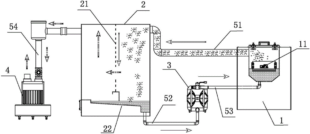
Figure 201220309721

The utility model relates to a paint spraying device, comprising a paint spray box (1), a paint recovery box (2), a paint pump (3) and a blower (4); the upper end of the spray paint box (1) and the paint recovery box (2) The upper end of the upper end is connected and sealed through the first connecting pipe (51), wherein, the middle part of the spray box (1) is provided with a feed port (11) connecting the spray box (1) with the outside atmosphere, below the feed port (11) The spraying box (1) is filled with paint; the inlet of the paint pump (3) is connected to the paint recovery box (2), and the outlet is connected to the spraying box (1) to transport the paint recovered in the paint recovery box (2) to the spraying box (1 ) below; the air blower (4) is connected to the upper part of the paint recovery box (2) and sucks air. The realization of the embodiment of the utility model can not only make the paint evenly distributed on the surface of the workpiece, but also effectively prevent the paint from diffusing into the air outside the device, thereby preventing the air from being polluted, ensuring the health of the sprayers, and at the same time realizing To make full use of 100% of the paint.

Figure 201220309721

Description

一种涂料喷涂装置A paint spraying device

技术领域 technical field

本实用新型属于喷涂技术领域,尤其涉及一种涂料喷涂装置。The utility model belongs to the technical field of spraying, in particular to a paint spraying device.

背景技术 Background technique

目前,现有的涂料喷涂工艺主要采用喷枪将涂料雾化后再对工件进行喷涂;但是,实用新型人发现现有的这种涂料喷涂工艺至少存在以下几个缺点:At present, the existing paint spraying process mainly uses a spray gun to atomize the paint and then sprays the workpiece; however, the utility model finds that the existing paint spraying process has at least the following disadvantages:

第一,如图1所示,涂料经喷枪1喷出后,会形成一个扇面形的雾化区A;该雾化区A内的雾化涂料仅有一部分会附着到工件2上,而其余的雾化涂料有些是直接扩散到空气中,有些是经过与工件2表面的撞击后溅射到空气中;在现有的技术条件下,这些扩散到空气中雾化涂料还没有很好的办法进行回收,因此这种喷涂工艺不仅会造成涂料的严重浪费,而且会对空气造成严重污染、危害喷涂人员的身体健康。长期的生产实践表明:对于条状的工件而言,这种喷涂工艺对涂料的有效利用率不超过30%。First, as shown in Figure 1, after the paint is sprayed from the spray gun 1, a fan-shaped atomization area A will be formed; only a part of the atomized paint in the atomization area A will adhere to the workpiece 2, while the rest Some of the atomized coatings are directly diffused into the air, and some are splashed into the air after impacting the surface of the workpiece 2; under the existing technical conditions, there is no good way for these atomized coatings to diffuse into the air Therefore, this spraying process will not only cause serious waste of paint, but also cause serious air pollution and endanger the health of sprayers. Long-term production practice shows that: for strip-shaped workpieces, the effective utilization rate of paint by this spraying process does not exceed 30%.

第二,如图1所示,利用喷枪1与喷枪1′对工件2进行喷涂;其中,涂料经喷枪1喷出后会形成一个扇面形的雾化区A,涂料经喷枪1′喷出后会形成一个扇面形的雾化区A′;在实际操作中,雾化区A与雾化区A′会不可避免地存在一定范围的重合区域,即为重合雾化区S。在对工件2进行喷涂的过程中,雾化区A所覆盖的工件2的表面会附着一层涂料,而雾化区A′所覆盖的工件2的表面也会附着一层涂料;由于雾化区A与雾化区A′之间存在着重合雾化区S,因此重合雾化区S所覆盖的工件2的表面会形成两层涂料。这就会造成工件2表面的涂层不均匀,甚至造成涂料的漏喷和流挂,因此不仅会影工件2的外观美感,而且可能导致工件2的性能不均一。Second, as shown in Figure 1, use the spray gun 1 and the spray gun 1' to spray the workpiece 2; wherein, after the paint is sprayed out from the spray gun 1, a fan-shaped atomization area A will be formed, and after the paint is sprayed out from the spray gun 1' A fan-shaped atomization area A' will be formed; in actual operation, there will inevitably be a certain range of overlapping areas between the atomization area A and the atomization area A', which is the overlapping atomization area S. In the process of spraying the workpiece 2, a layer of paint will be attached to the surface of the workpiece 2 covered by the atomization area A', and a layer of paint will also be attached to the surface of the workpiece 2 covered by the atomization area A'; There is an overlapping atomization area S between the area A and the atomization area A', so the surface of the workpiece 2 covered by the overlapping atomization area S will form two layers of paint. This will cause the coating on the surface of the workpiece 2 to be uneven, and even cause paint leakage and sagging, which will not only affect the aesthetic appearance of the workpiece 2, but also may cause uneven performance of the workpiece 2.

实用新型内容 Utility model content

本实用新型提供了一种涂料喷涂装置,不仅可以使涂料均匀分布在工件的表面,而且能够有效避免涂料扩散到装置外部的空气中,进而使空气免受污染,保证了喷涂人员的身体健康,同时还实现了对涂料百分之一百的充分利用。The utility model provides a paint spraying device, which not only can make the paint evenly distributed on the surface of the workpiece, but also can effectively prevent the paint from diffusing into the air outside the device, thereby preventing the air from being polluted and ensuring the health of sprayers. Also realized the full utilization of 100% to coating simultaneously.

本实用新型的目的是通过以下技术方案来实现的:The purpose of this utility model is achieved through the following technical solutions:

一种涂料喷涂装置,包括喷涂箱1、涂料回收箱2、涂料泵3和鼓风机4;A paint spraying device, comprising a paint spray box 1, a paint recovery box 2, a paint pump 3 and a blower 4;

所述的喷涂箱1的上端部与涂料回收箱2的上端部通过第一连接管51连通且密闭,其中,所述喷涂箱1的中部设有连通喷涂箱1与外界大气的进料口11,进料口11下方的喷涂箱1内盛装有涂料;The upper end of the spraying box 1 and the upper end of the paint recovery box 2 are communicated and sealed through the first connecting pipe 51, wherein, the middle part of the spraying box 1 is provided with a feed port 11 connecting the spraying box 1 with the outside atmosphere , paint is filled in the spray box 1 below the feed port 11;

涂料泵3的进口连接涂料回收箱2,出口连接喷涂箱1将涂料回收箱2内回收的涂料输送至喷涂箱1下方;The inlet of the paint pump 3 is connected to the paint recovery box 2, and the outlet is connected to the spraying box 1 to transport the paint recovered in the paint recovery box 2 to the bottom of the spraying box 1;

鼓风机4连接涂料回收箱2上部并抽气。The blower 4 is connected to the upper part of the paint recovery box 2 and sucks air.

优选地,相应的进料口11的形状与待加工工件的横截面形状相同。Preferably, the shape of the corresponding feed opening 11 is the same as the cross-sectional shape of the workpiece to be processed.

优选地,相应喷涂箱1内所盛装涂料的液面位于所述进料口11的下方;Preferably, the liquid level of the paint contained in the corresponding spraying box 1 is located below the feed port 11;

优选地,相应涂料回收箱2的内部沿竖直方向设有分隔板21;Preferably, the inside of the corresponding paint recovery box 2 is provided with a partition plate 21 along the vertical direction;

涂料回收箱2的右侧的上端部通过第一连接管51与喷涂箱1的上端部连通;The upper end of the right side of the paint recovery box 2 communicates with the upper end of the spraying box 1 through the first connecting pipe 51;

涂料回收箱2的左侧的上端部通过第四连接管54与鼓风机4连通。The left upper end of the paint recovery tank 2 communicates with the air blower 4 through the fourth connection pipe 54 .

优选地,相应的分隔板21由涂料回收箱2的顶部延伸至涂料回收箱2的下部,并且位于涂料回收箱2中下部的分隔板21上设有开口。Preferably, the corresponding partition board 21 extends from the top of the paint recovery tank 2 to the lower part of the paint recovery tank 2 , and the partition board 21 located in the middle and lower part of the paint recovery tank 2 is provided with an opening.

优选地,相应涂料回收箱2的底面为坡面22,并且位于涂料回收箱2左侧的坡面高于位于涂料回收箱2右侧的坡面。Preferably, the bottom surface of the corresponding paint recovery box 2 is a slope 22 , and the slope on the left side of the paint recovery box 2 is higher than the slope on the right side of the paint recovery box 2 .

优选地,相应的涂料泵3的进口通过第二连接管52与涂料回收箱2的底部连通且密闭;涂料泵3的出口通过第三连接管53与喷涂箱1连通且密闭,并将涂料回收箱2内回收的涂料输送至喷涂箱1下方。Preferably, the inlet of the corresponding paint pump 3 is communicated and sealed with the bottom of the paint recovery tank 2 through the second connecting pipe 52; the outlet of the paint pump 3 is communicated and sealed with the spray tank 1 through the third connecting pipe 53, and the paint is recovered The paint recovered in the box 2 is conveyed to the bottom of the spraying box 1.

由上述本实用新型实施例提供的技术方案可以看出,本实用新型实施例的鼓风机4可以不断通过涂料回收箱2从喷涂箱1中抽取空气,由于该装置的各部件密封良好并且各部件间均采用密封连接,因此空气仅能通过喷涂箱1的进料口11流入该装置;当工件由进料口11进入喷涂箱1时,工件表面与进料口11之间会存在一定的缝隙,空气以高速流入喷涂箱1并流经涂料表面,进而使涂料充分雾化;由于喷涂箱1空间有限,大量雾化涂料均悬浮在这一空间时,该喷涂箱1内雾化涂料的密度是基本一致的,因此这些雾化涂料会均匀附着在工件的表面,从而实现对于工件的均匀喷涂。同时,没有附着在工件表面的雾化涂料会随着空气一同流入涂料回收箱2的右侧,此时由于该腔体空间较大,空气的流动速度突然变缓,同时还受到了涂料回收箱2内壁以及分隔板21阻挡,因此空气中的雾化涂料会与空气发生分离,并在重力作用下沉降到涂料回收箱2的底部;这些汇聚于涂料回收箱2底部的涂料会在涂料泵3的作用下抽回到喷涂箱1,因而实现了对涂料百分之一百的充分循环利用;而涂料回收箱2的右侧与雾化涂料分离后的干净空气会通过分隔板21上所设置的开口流入到涂料回收箱2的左侧,并在鼓风机4的作用下排除到大气中;由于这些空气是已经与涂料分离的洁净空气,而该装置的各部分密封良好并不会漏气,因此该装置能够有效避免涂料扩散到装置外部的空气中,进而使空气免受污染,保证了喷涂人员的身体健康。As can be seen from the technical solutions provided by the above-mentioned embodiments of the present invention, the blower 4 of the embodiments of the present invention can continuously extract air from the spraying tank 1 through the paint recovery tank 2, because each part of the device is well sealed and the gap between each part Both adopt sealed connection, so the air can only flow into the device through the feed port 11 of the spray box 1; when the workpiece enters the spray box 1 from the feed port 11, there will be a certain gap between the workpiece surface and the feed port 11, The air flows into the spray box 1 at high speed and flows through the surface of the paint, thereby fully atomizing the paint; due to the limited space of the spray box 1, when a large amount of atomized paint is suspended in this space, the density of the atomized paint in the spray box 1 is Basically consistent, so these atomized paints will evenly adhere to the surface of the workpiece, so as to achieve uniform spraying on the workpiece. At the same time, the atomized paint that is not attached to the surface of the workpiece will flow into the right side of the paint recovery box 2 together with the air. At this time, due to the large space of the cavity, the flow speed of the air suddenly slows down, and it is also affected by the paint recovery box. 2 inner walls and partitions 21 block, so the atomized paint in the air will be separated from the air, and will settle to the bottom of the paint recovery tank 2 under the action of gravity; 3 under the action of pumping back to the spraying box 1, thereby realizing the full recycling of 100% of the paint; and the clean air separated from the atomized paint on the right side of the paint recovery box 2 will pass through the partition plate 21 The provided opening flows into the left side of the paint recovery box 2, and is discharged into the atmosphere under the action of the blower 4; since these airs are clean air that has been separated from the paint, each part of the device is well sealed and will not leak Therefore, the device can effectively prevent the paint from diffusing into the air outside the device, thereby protecting the air from pollution and ensuring the health of sprayers.

附图说明 Description of drawings

为了更清楚地说明本实用新型实施例或现有技术中的技术方案,下面将对实施例或现有技术描述中所需要使用的附图作简单地介绍,显而易见地,下面描述中的附图仅仅是本实用新型的一些实施例,对于本领域普通技术人员来讲,在不付出创造性劳动的前提下,还可以根据这些附图获得其他的附图。In order to more clearly illustrate the technical solutions in the embodiments of the present invention or the prior art, the following will briefly introduce the accompanying drawings that need to be used in the description of the embodiments or the prior art. Obviously, the accompanying drawings in the following description These are only some embodiments of the utility model, and those skilled in the art can also obtain other drawings based on these drawings without creative work.

图1为现有技术中利用喷枪进行喷涂的涂料喷涂工艺示意图;Fig. 1 is the paint spraying process schematic diagram that utilizes spray gun to carry out spraying in the prior art;

图2为本实用新型所提供的涂料喷涂装置的结构示意图。Fig. 2 is a structural schematic diagram of the paint spraying device provided by the utility model.

具体实施方式 Detailed ways

下面将结合本实用新型实施例中的附图,对本实用新型实施例中的技术方案进行清楚、完整地描述,可以理解的是,所描述的实施例仅是本实用新型一部分实施例,而不是全部的实施例。基于本实用新型中的实施例,本领域普通技术人员在没有做出创造性劳动前提下所获得的所有其他实施例,都属于本实用新型保护的范围。The technical solutions in the embodiments of the present invention will be clearly and completely described below in conjunction with the accompanying drawings in the embodiments of the present invention. It should be understood that the described embodiments are only part of the embodiments of the present invention, rather than Full examples. Based on the embodiments of the present utility model, all other embodiments obtained by persons of ordinary skill in the art without making creative efforts belong to the scope of protection of the present utility model.

下面将结合附图对本实用新型实施例所提供的涂料喷涂装置作进一步地详细描述。The paint spraying device provided by the embodiment of the present invention will be further described in detail with reference to the accompanying drawings.

如图2所示,一种涂料喷涂装置,其具体结构可以包括喷涂箱1、涂料回收箱2、涂料泵3和鼓风机4;喷涂箱1的上端部与涂料回收箱2的上端部通过第一连接管51连通且密闭;喷涂箱1的中部设有连通喷涂箱1与外界大气的进料口11,进料口11下方的喷涂箱1内盛装有涂料;鼓风机4连接涂料回收箱2上部并抽气;As shown in Figure 2, a kind of paint spraying device, its concrete structure can comprise spray box 1, paint recovery box 2, paint pump 3 and blower 4; The upper end of spray box 1 and the upper end of paint recovery box 2 pass through first The connecting pipe 51 is connected and airtight; the middle part of the spray box 1 is provided with a feed port 11 connecting the spray box 1 with the outside atmosphere, and the spray box 1 below the feed port 11 is filled with paint; the blower 4 is connected to the top of the paint recovery box 2 and pump air;

涂料泵3的进口连接涂料回收箱2,出口连接喷涂箱1将涂料回收箱2内回收的涂料输送至喷涂箱1下方;在实际应用中,涂料泵3的进口最好通过第二连接管52与涂料回收箱2的底部连通且密闭;涂料泵3的出口最好通过第三连接管53与喷涂箱1连通且密闭,从而使涂料回收箱2内所回收的涂料能够尽可能地输送至进料口11下方的喷涂箱1,以为涂料百分之一百的充分利用提供必要的条件。The inlet of the paint pump 3 is connected to the paint recovery box 2, and the outlet is connected to the spraying box 1 to transport the paint recovered in the paint recovery box 2 to the bottom of the spraying box 1; It is communicated with the bottom of the paint recovery tank 2 and sealed; the outlet of the paint pump 3 is preferably communicated with the spray tank 1 through the third connecting pipe 53 and sealed, so that the recovered paint in the paint recovery tank 2 can be transported to the inlet as much as possible. The spraying box 1 below the feed port 11 provides necessary conditions for the full utilization of 100% of the paint.

其中,相应的进料口11的形状与待加工工件的横截面形状相同,并且该进料口11的尺寸应略大于待加工工件的横截面的尺寸;在实际应用中,该进料口11的尺寸最好以待加工工件放入进料口11后待加工工件的外表面仍与进料口11之间存在1毫米至30毫米的间隙为宜;这样不仅可以使空气能够顺畅地流入到喷涂箱1内,而且能够使空气具备一个较高的流动速度,从而为涂料的雾化提供必要的实施条件。同时,相应的喷涂箱1内所盛装涂料的液面位于所述进料口11的下方,在实际应用中,喷涂箱1内所盛装涂料的液面最好位于进料口11下方的4毫米至50毫米处;这样既可以保证涂料不会由进料口11溢出,又能使空气流入喷涂箱1时能够尽可能地接近涂料表面,进而保证涂料能够在高速空气的作用下充分雾化,以实现对工件的均匀喷涂。Wherein, the shape of the corresponding feed port 11 is the same as the cross-sectional shape of the workpiece to be processed, and the size of the feed port 11 should be slightly larger than the size of the cross-section of the workpiece to be processed; in practical applications, the feed port 11 It is advisable that there is still a gap of 1 mm to 30 mm between the outer surface of the workpiece to be processed and the feed inlet 11 after the workpiece to be processed is put into the feed port 11; In the spraying box 1, the air can have a higher flow velocity, thereby providing the necessary implementation conditions for the atomization of the paint. Simultaneously, the liquid level of the contained coating in the corresponding spraying box 1 is positioned at the below of the described feed inlet 11, and in actual application, the liquid level of the contained coating in the spraying box 1 is preferably positioned at 4 millimeters below the feed inlet 11 to 50 mm; this can ensure that the paint will not overflow from the feed port 11, and can make the air flow into the spray box 1 as close as possible to the paint surface, thereby ensuring that the paint can be fully atomized under the action of high-speed air. In order to achieve uniform spraying on the workpiece.

具体地,涂料回收箱2的内部沿竖直方向设有分隔板21;该分隔板21由涂料回收箱2的顶部延伸至涂料回收箱2的下部,并且位于涂料回收箱2中下部的分隔板21上设有开口;涂料回收箱2的右侧的上端部通过第一连接管51与喷涂箱1的上端部连通,涂料回收箱2的左侧的上端部通过第四连接管54与鼓风机4连通;由于涂料回收箱2内的分隔板21由涂料回收箱2的顶部延伸至涂料回收箱2的下部,因此由喷涂箱1流入涂料回收箱2的气体无法直接流入涂料回收箱2的左侧,而只能通过位于涂料回收箱2中下部的分隔板21上所设置的开口流入涂料回收箱2的左侧;当含有雾化涂料的空气从涂料回收箱2的右侧流入涂料回收箱2时,由于该涂料回收箱2右侧空间较大,空气的流动速度突然变缓,同时还受到了涂料回收箱2内壁以及分隔板21阻挡,因此空气中的雾化涂料会与空气发生分离,并在重力作用下沉降到涂料回收箱2的底部,以供涂料泵3将其传送至喷涂箱1;为了方便空气中所夹带的涂料能够更好地汇集在涂料回收箱2的底部,在实际应用中,相应的涂料回收箱2的底面最好为坡面22,并且位于涂料回收箱2左侧的坡面高于位于涂料回收箱2右侧的坡面。Specifically, the inside of the paint recovery box 2 is provided with a partition plate 21 in the vertical direction; Partition plate 21 is provided with opening; The upper end of the right side of paint recovery box 2 is communicated with the upper end of spraying box 1 by first connecting pipe 51, and the upper end of left side of paint recovery box 2 is through the 4th connecting pipe 54 It communicates with the blower 4; since the partition plate 21 in the paint recovery tank 2 extends from the top of the paint recovery tank 2 to the bottom of the paint recovery tank 2, the gas flowing into the paint recovery tank 2 from the spray tank 1 cannot directly flow into the paint recovery tank 2, but can only flow into the left side of the paint recovery tank 2 through the opening provided on the partition plate 21 at the lower part of the paint recovery tank 2; When flowing into the paint recovery box 2, due to the large space on the right side of the paint recovery box 2, the flow velocity of the air suddenly slows down, and it is also blocked by the inner wall of the paint recovery box 2 and the partition plate 21, so the atomized paint in the air It will be separated from the air and settle to the bottom of the paint recovery tank 2 under the action of gravity for the paint pump 3 to transfer it to the spray tank 1; in order to facilitate the paint entrained in the air to better collect in the paint recovery tank 2, in practical applications, the bottom surface of the corresponding paint recovery box 2 is preferably a slope 22, and the slope on the left side of the paint recovery box 2 is higher than the slope on the right side of the paint recovery box 2.

进一步地,本实用新型实施例所提供的涂料喷涂装置的工作原理如下:Further, the working principle of the paint spraying device provided by the embodiment of the present invention is as follows:

(1)对工件进行均匀喷涂的原理(1) The principle of uniform spraying on the workpiece

众所周知,当气流高速掠过液体的表面时,液体会被吹散成颗粒状小液滴悬浮于空气中,这就是雾化原理。本实用新型实施例所提供的涂料喷涂装置正是利用了这一原理:当本装置启动时,鼓风机4会不断通过涂料回收箱2从喷涂箱1中抽取空气,由于该装置的各部件密封良好并且各部件间均采用密封连接,因此空气仅能通过喷涂箱1的进料口11流入装置;由于该进料口11的形状与工件横截面形状相同,仅是尺寸略大于工件横截面,因此当工件由进料口11进入喷涂箱1时,工件表面与进料口11之间会存在一定的缝隙,空气仅能通过该缝隙流入喷涂箱1;由于鼓风机4的运转功率并没有发生变化,因此空气只能以高速流入喷涂箱1;由于喷涂箱1内所盛装涂料的液面恰好位于所述进料口11的下方,因此当空气以高速流经涂料表面时,涂料会因雾化原理而发生雾化,进而使整个喷涂箱1内充满雾化涂料;由于喷涂箱1空间有限,大量雾化涂料均悬浮在这一空间时,该喷涂箱1内各处的雾化涂料的密度是基本一致的,因此这些雾化涂料会均匀附着在工件的表面,以实现对于工件的均匀喷涂。根据该涂料喷涂装置的这一工作原理可知,空气流经涂料表面的速度越快涂料的雾化程度就越高,空气流经涂料表面的速度越慢涂料的雾化程度也就越慢,因此可以通过调整鼓风机4的运转功率和/或调整工件放入进料口11时工件表面与进料口11之间的缝隙宽度,来调整空气流入喷涂箱1的流速,进而调节涂料的雾化程度。在实际应用中,无论工件的表面形状如何复杂,由于雾化涂料在此空间内是均匀分布的,所以涂料都能均匀附着在工件的表面,进而保证了对工件的喷涂厚度的一致性。As we all know, when the air flow passes over the surface of the liquid at high speed, the liquid will be blown into granular droplets suspended in the air, which is the principle of atomization. The paint spraying device provided by the embodiment of the utility model just utilizes this principle: when the device is started, the air blower 4 can continuously extract air from the spraying box 1 through the paint recovery box 2, because each part of the device is well sealed And each part is sealed and connected, so the air can only flow into the device through the feed port 11 of the spray box 1; because the shape of the feed port 11 is the same as the cross-sectional shape of the workpiece, only the size is slightly larger than the cross-section of the workpiece, so When the workpiece enters the spraying box 1 by the feed port 11, there will be a certain gap between the workpiece surface and the feed port 11, and the air can only flow into the spraying box 1 through the gap; since the operating power of the blower 4 does not change, Therefore air can only flow into the spraying box 1 at a high speed; because the liquid level of the paint contained in the spraying box 1 is just below the described feed port 11, when the air flows through the surface of the coating at a high speed, the coating will be sprayed due to the principle of atomization. And atomization takes place, and then make in the whole spraying box 1, be full of atomized paint; Because spraying box 1 space is limited, when a large amount of atomized paints are all suspended in this space, the density of the atomized paint everywhere in this spraying box 1 is Basically consistent, so these atomized paints will evenly adhere to the surface of the workpiece to achieve uniform spraying on the workpiece. According to the working principle of the paint spraying device, the faster the air flows through the surface of the paint, the higher the degree of atomization of the paint, and the slower the speed of air flowing through the surface of the paint, the slower the degree of atomization of the paint. Therefore By adjusting the operating power of the blower 4 and/or adjusting the width of the gap between the workpiece surface and the feed port 11 when the workpiece is put into the feed port 11, the flow rate of the air flowing into the spraying box 1 can be adjusted, thereby adjusting the atomization degree of the paint . In practical application, no matter how complicated the surface shape of the workpiece is, since the atomized paint is evenly distributed in this space, the paint can be evenly attached to the surface of the workpiece, thereby ensuring the consistency of the spray thickness of the workpiece.

(2)涂料进行循环利用的原理(2) The principle of recycling paint

没有附着在工件表面的雾化涂料会随着空气一同流入涂料回收箱2的右侧,此时由于该腔体空间较大,空气的流动速度突然变缓,同时还受到了涂料回收箱2内壁以及分隔板21阻挡,因此空气中的雾化涂料会与空气发生分离,并在重力作用下沉降到涂料回收箱2的底部;这些汇聚于涂料回收箱2底部的涂料会在涂料泵3的作用下抽回到喷涂箱1,因而实现了对涂料百分之一百的充分循环利用;而涂料回收箱2的右侧与雾化涂料分离后的干净空气会通过位于涂料回收箱2下部的分隔板21上所设置的开口流入到涂料回收箱2的左侧,并在鼓风机4的作用下排除到大气中;由于这些空气是已经与涂料分离的洁净空气,而该装置的各部分密封良好并不会漏气,因此该装置能够有效避免涂料扩散到装置外部的空气中,进而使空气免受污染,保证了喷涂人员的身体健康。The atomized paint that is not attached to the surface of the workpiece will flow into the right side of the paint recovery box 2 together with the air. At this time, due to the large space in the cavity, the flow speed of the air suddenly slows down, and it is also affected by the inner wall of the paint recovery box 2. And partition plate 21 blocks, so the atomized paint in the air can separate with air, and settle down to the bottom of paint recovery tank 2 under the action of gravity; Under the action, it is pumped back to the spraying box 1, thereby realizing the full recycling of 100% of the paint; and the clean air separated from the atomized paint on the right side of the paint recovery box 2 will pass through the bottom of the paint recovery box 2. The opening provided on the dividing plate 21 flows into the left side of the paint recovery box 2, and is discharged into the atmosphere under the effect of the blower 4; because these airs are clean air that has been separated from the paint, and each part of the device is sealed It is good and will not leak air, so the device can effectively prevent the paint from spreading into the air outside the device, thereby preventing the air from being polluted and ensuring the health of sprayers.

需要说明的是,本申请文件中所述的第一连接管51、第二连接管52、第三连接管53和第四连接管54可以均为现有技术中管路,这四种连接管可以采用相同的管路,也可以采用不同的管路。此外,经过实验测算,该涂料喷涂装置循环一周的时间大约为3分钟,因此本实用新型实施例所提供的涂料喷涂装置具有一个较高的处理速度。It should be noted that the first connecting pipe 51, the second connecting pipe 52, the third connecting pipe 53 and the fourth connecting pipe 54 described in this application document may all be pipelines in the prior art, and these four connecting pipes The same pipeline may be used, or different pipelines may be used. In addition, according to experimental calculations, the cycle time of the paint spraying device is about 3 minutes, so the paint spraying device provided by the embodiment of the present invention has a relatively high processing speed.

可见,本实用新型实施例的实现能够不仅可以使涂料均匀分布在工件的表面,而且能够有效避免涂料扩散到装置外部的空气中,进而使空气免受污染,保证了喷涂人员的身体健康,同时还实现了对涂料百分之一百的充分利用。It can be seen that the realization of the embodiment of the utility model can not only make the paint evenly distributed on the surface of the workpiece, but also effectively prevent the paint from spreading into the air outside the device, thereby preventing the air from being polluted, ensuring the health of the sprayers, and at the same time It also achieves full utilization of 100% of the paint.

以上所述仅为本实用新型的较佳实施例而已,并不用以限制本实用新型,凡在本实用新型的精神和原则之内所作的任何修改、等同替换和改进等,均应包含在本实用新型的保护范围之内。The above descriptions are only preferred embodiments of the present utility model, and are not intended to limit the present utility model. Any modifications, equivalent replacements and improvements made within the spirit and principles of the present utility model shall be included in this utility model. within the scope of protection of utility models.

Claims (7)

1.一种涂料喷涂装置,其特征在于,包括喷涂箱(1)、涂料回收箱(2)、涂料泵(3)和鼓风机(4); 1. A paint spraying device, characterized in that it comprises a spray box (1), a paint recovery box (2), a paint pump (3) and a blower (4); 所述的喷涂箱(1)的上端部与涂料回收箱(2)的上端部通过第一连接管(51)连通且密闭,其中,所述喷涂箱(1)的中部设有连通喷涂箱(1)与外界大气的进料口(11),进料口(11)下方的喷涂箱(1)内盛装有涂料; The upper end of the spraying box (1) communicates with the upper end of the paint recovery box (2) through the first connecting pipe (51) and is sealed, wherein, the middle part of the spraying box (1) is provided with a communicating spraying box ( 1) The feed port (11) with the outside atmosphere, and the spray box (1) below the feed port (11) is filled with paint; 涂料泵(3)的进口连接涂料回收箱(2),出口连接喷涂箱(1)将涂料回收箱(2)内回收的涂料输送至喷涂箱(1)下方; The inlet of the paint pump (3) is connected to the paint recovery box (2), and the outlet is connected to the spraying box (1) to transport the recovered paint in the paint recovery box (2) to the bottom of the spraying box (1); 鼓风机(4)连接涂料回收箱(2)上部并抽气。 The air blower (4) is connected to the upper part of the paint recovery box (2) and sucked air. 2.根据权利要求1所述的涂料喷涂装置,其特征在于,所述进料口(11)的形状与待加工工件的横截面形状相同。 2. The paint spraying device according to claim 1, characterized in that, the shape of the feeding port (11) is the same as the cross-sectional shape of the workpiece to be processed. 3.根据权利要求1或2所述的涂料喷涂装置,其特征在于,喷涂箱(1)内所盛装涂料的液面位于所述进料口(11)的下方。 3. The paint spraying device according to claim 1 or 2, characterized in that, the liquid level of the paint contained in the spray tank (1) is located below the feed inlet (11). 4.根据权利要求1或2所述的涂料喷涂装置,其特征在于,涂料回收箱(2)的内部沿竖直方向设有分隔板(21); 4. The paint spraying device according to claim 1 or 2, characterized in that, the inside of the paint recovery box (2) is provided with a partition plate (21) along the vertical direction; 涂料回收箱(2)的右侧的上端部通过第一连接管(51)与喷涂箱(1)的上端部连通; The upper end of the right side of the paint recovery box (2) communicates with the upper end of the spraying box (1) through the first connecting pipe (51); 涂料回收箱(2)的左侧的上端部通过第四连接管(54)与鼓风机(4)连通。 The left upper end of the paint recovery box (2) communicates with the air blower (4) through a fourth connecting pipe (54). 5.根据权利要求4所述的涂料喷涂装置,其特征在于,所述的分隔板(21)由涂料回收箱(2)的顶部延伸至涂料回收箱(2)的下部,并且位于涂料回收箱(2)中下部的分隔板(21)上设有开口。 5. The paint spraying device according to claim 4, characterized in that, the partition plate (21) extends from the top of the paint recovery box (2) to the lower part of the paint recovery box (2), and is located at the bottom of the paint recovery box (2). The partition plate (21) in the lower part of the box (2) is provided with an opening. 6.根据权利要求1或2所述的涂料喷涂装置,其特征在于,所述涂料回收箱(2)的底面为坡面(22),并且位于涂料回收箱(2)左侧的坡面高于位于涂料回收箱(2)右侧的坡面。 6. The paint spraying device according to claim 1 or 2, characterized in that, the bottom surface of the paint recovery box (2) is a slope (22), and the slope on the left side of the paint recovery box (2) is as high as on the slope to the right of the paint recovery bin (2). 7.根据权利要求1或2所述的涂料喷涂装置,其特征在于,涂料泵(3)的进口通过第二连接管(52)与涂料回收箱(2)的底部连通且密闭;涂料泵(3)的出口通过第三连接管(53)与喷涂箱(1)连通且密闭,并将涂料回收箱(2)内回收的涂料输送至喷涂箱(1) 下方。  7. The paint spraying device according to claim 1 or 2, characterized in that, the inlet of the paint pump (3) is connected and sealed with the bottom of the paint recovery tank (2) through the second connecting pipe (52); the paint pump ( 3) The outlet of the outlet is connected and sealed with the spraying box (1) through the third connecting pipe (53), and the paint recovered in the paint recovery box (2) is transported to the bottom of the spraying box (1). the
CN2012203097217U 2012-06-28 2012-06-28 Coating spaying device Expired - Lifetime CN202752149U (en)

Priority Applications (1)

Application Number Priority Date Filing Date Title
CN2012203097217U CN202752149U (en) 2012-06-28 2012-06-28 Coating spaying device

Applications Claiming Priority (1)

Application Number Priority Date Filing Date Title
CN2012203097217U CN202752149U (en) 2012-06-28 2012-06-28 Coating spaying device

Publications (1)

Publication Number Publication Date
CN202752149U true CN202752149U (en) 2013-02-27

Family

ID=47731344

Family Applications (1)

Application Number Title Priority Date Filing Date
CN2012203097217U Expired - Lifetime CN202752149U (en) 2012-06-28 2012-06-28 Coating spaying device

Country Status (1)

Country Link
CN (1) CN202752149U (en)

Cited By (3)

* Cited by examiner, † Cited by third party
Publication number Priority date Publication date Assignee Title
CN102728510A (en) * 2012-06-28 2012-10-17 大连诚汇机械设备有限公司 Device and method for spraying coating
CN105081234A (en) * 2015-08-17 2015-11-25 廖子贵 Flow coating device for casting
CN105108047A (en) * 2015-08-19 2015-12-02 廖子贵 Casting flow coating device with warning function

Similar Documents

Publication Publication Date Title
CN201366390Y (en) Water curtain venturi-type spray-painting booth
CN202224301U (en) Energy-saving water curtain paint spraying chamber for wooden door coating
CN104307278B (en) A kind of dust collector of water curtain
CN103691612A (en) Water screen type spray room
CN204685374U (en) Novel two stage cascade spray booth
CN204147702U (en) A kind of dust collector of water curtain
CN102728510A (en) Device and method for spraying coating
CN206794072U (en) Paint spraying and baking device is used in a kind of furniture processing
CN205462919U (en) A spray paint recovery device
CN205235653U (en) Processing operation station wet dedusting system
CN108144777A (en) A kind of environment-friendly type color steel coating machine
CN208066615U (en) A kind of reciprocating paint spraying machine
CN105195371B (en) A kind of paint spraying rinsing device
CN204319979U (en) Lacquer spraying waste gas treating apparatus
CN204429029U (en) Pneumatic type dust catalytic converter
CN206631836U (en) One kind spraying clout recycle device
CN206965396U (en) A kind of water mist dust-removing system
CN207270984U (en) Oil gas paint thing processor
CN201940320U (en) Latex recycling unit
CN204251751U (en) A kind of chromium mist tower spray equipment
CN210151372U (en) A equipment for spraying of panty-shape diapers parcel layer
CN206064714U (en) A kind of novel intelligent sprays water-screen cabinet
CN201324701Y (en) Clean-type spray booth
CN208991099U (en) An environmentally friendly paint spraying workshop
CN205084939U (en) Water washing device sprays paint

Legal Events

Date Code Title Description
C14 Grant of patent or utility model
GR01 Patent grant
ASS Succession or assignment of patent right

Owner name: NIU LIANG

Free format text: FORMER OWNER: DALIAN CHENGHUI MACHINERY EQUIPMENT CO., LTD.

Effective date: 20141021

C41 Transfer of patent application or patent right or utility model
TR01 Transfer of patent right

Effective date of registration: 20141021

Address after: 116000 1-6-1, 185 Shandong Road, Ganjingzi District, Liaoning, Dalian

Patentee after: Niu Liang

Address before: 116000 Liaoning Province, Dalian city Ganjingzi District Road No. 15 977-5 southwest Fang Ming Yuan axis -16

Patentee before: Dalian Chenghui Machinery Equipment Co., Ltd.

AV01 Patent right actively abandoned

Granted publication date: 20130227

Effective date of abandoning: 20141210

AV01 Patent right actively abandoned

Granted publication date: 20130227

Effective date of abandoning: 20141210

RGAV Abandon patent right to avoid regrant