CN202751962U - Water-air mixing device with annular air-inflow mode - Google Patents
Water-air mixing device with annular air-inflow mode Download PDFInfo
- Publication number
- CN202751962U CN202751962U CN201220463543.3U CN201220463543U CN202751962U CN 202751962 U CN202751962 U CN 202751962U CN 201220463543 U CN201220463543 U CN 201220463543U CN 202751962 U CN202751962 U CN 202751962U
- Authority
- CN
- China
- Prior art keywords
- air
- water
- pipe
- water inlet
- mixing device
- Prior art date
- Legal status (The legal status is an assumption and is not a legal conclusion. Google has not performed a legal analysis and makes no representation as to the accuracy of the status listed.)
- Expired - Lifetime
Links
- XLYOFNOQVPJJNP-UHFFFAOYSA-N water Substances O XLYOFNOQVPJJNP-UHFFFAOYSA-N 0.000 claims abstract description 43
- 102000004169 proteins and genes Human genes 0.000 claims abstract description 8
- 108090000623 proteins and genes Proteins 0.000 claims abstract description 8
- 238000000034 method Methods 0.000 description 3
- 241000238634 Libellulidae Species 0.000 description 2
- 238000010586 diagram Methods 0.000 description 1
Images


Classifications
-
- Y—GENERAL TAGGING OF NEW TECHNOLOGICAL DEVELOPMENTS; GENERAL TAGGING OF CROSS-SECTIONAL TECHNOLOGIES SPANNING OVER SEVERAL SECTIONS OF THE IPC; TECHNICAL SUBJECTS COVERED BY FORMER USPC CROSS-REFERENCE ART COLLECTIONS [XRACs] AND DIGESTS
- Y02—TECHNOLOGIES OR APPLICATIONS FOR MITIGATION OR ADAPTATION AGAINST CLIMATE CHANGE
- Y02W—CLIMATE CHANGE MITIGATION TECHNOLOGIES RELATED TO WASTEWATER TREATMENT OR WASTE MANAGEMENT
- Y02W10/00—Technologies for wastewater treatment
- Y02W10/10—Biological treatment of water, waste water, or sewage
Landscapes
- Jet Pumps And Other Pumps (AREA)
Abstract
本实用新型的一种蛋白质分离器用的环状进气的水气混合装置,它包含进水管,管套,进气管,水泵口进水接管;所述管套与水泵口进水接管套接形成气室,所述进水管插入气室中。所述进气管与气室连通。当被压缩的高速水流,通过管套时对管套内的环状气室造成负压,并带走气室里面的空气,空气带走后,新的空气又通过进气管,从而使得水气均匀混合。该实用新型的环状进气的水气混合装置不仅使得进气量增大,而且水气混合更加均匀,稳定,从而使得蛋白质分离器的处理效能大大增加。
The utility model relates to a water-gas mixing device with annular air intake for a protein separator, which includes a water inlet pipe, a pipe sleeve, an air intake pipe, and a water inlet connecting pipe of a water pump; The air chamber, the water inlet pipe is inserted into the air chamber. The air intake pipe communicates with the air chamber. When the compressed high-speed water flow passes through the pipe sleeve, it creates a negative pressure on the annular air chamber in the pipe sleeve, and takes away the air in the air chamber. After the air is taken away, the new air passes through the intake pipe again, so that the water vapor Mix well. The water-air mixing device of the utility model not only increases the intake air volume, but also makes the water-air mixing more uniform and stable, thereby greatly increasing the processing efficiency of the protein skimmer.
Description
技术领域 technical field
本实用新型涉及一种水气混合装置,特别是一种水族箱蛋白质分离器用的环状进气的水气混合装置。The utility model relates to a water-air mixing device, in particular to a water-air mixing device with annular air intake for the protein separator of the aquarium.
背景技术 Background technique
目前,现有的蛋白质分离器水气混合装置大多为单点进气方式,虽然结构简单,但是水气混合不均匀、不稳定,造成蛋白质分离器的处理效能大幅下降。At present, most of the existing water-air mixing devices for protein skimmers use a single-point air intake method. Although the structure is simple, the water-air mixing is uneven and unstable, resulting in a significant drop in the processing efficiency of the protein skimmer.
发明内容 Contents of the invention
本实用新型提供了一种能有效解决现有蛋白质分离器水气混合装置水气混合不均匀,不稳定的问题,本实用新型提供一种水气混合装置,该装置设计成环状进气口,不仅进气量大,而且水气混合更加均匀,稳定。The utility model provides a method that can effectively solve the problem of uneven and unstable water-gas mixing in the existing protein separator water-gas mixing device. The utility model provides a water-gas mixing device, which is designed as an annular air inlet , not only the air intake is large, but also the water-air mixing is more uniform and stable.
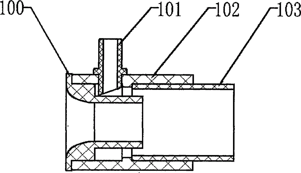
本实用新型的目的是这样实现的,它包含进水管(100),管套(102),进气管(101),水泵口进水接管(103),进水管(100)插入由管套(102)与水泵口进水接管(103)套接而成的气室,形成圆环状气室,进水管(100)的末端并延伸出气室,进水管(100)的管内径从进水口到出水口形成从大到小的逐渐收小的形状,进气管(101)与管套(102)的气室连通。The purpose of this utility model is achieved in that it comprises a water inlet pipe (100), a pipe sleeve (102), an air inlet pipe (101), a water pump inlet connection pipe (103), and the water inlet pipe (100) is inserted into the water inlet pipe (102) by the pipe sleeve (102). ) and the water inlet connection pipe (103) of the water pump mouth are sleeved to form an annular air chamber, and the end of the water inlet pipe (100) extends out of the air chamber. The nozzle forms a gradually narrowing shape from large to small, and the air inlet pipe (101) communicates with the air chamber of the pipe sleeve (102).
本实用新型的环状进气的水气混合装置的进气面积增大,从而使得进气量增大,水气混合更加均匀和稳定,最终使得蛋白质分离器的处理效能大大增加。The air intake area of the annular air intake water-air mixing device of the utility model is increased, so that the intake air volume is increased, the water-air mixing is more uniform and stable, and finally the processing efficiency of the protein separator is greatly increased.
附图说明 Description of drawings
下面结合附图详述本实用新型的具体结构。The concrete structure of the present utility model is described in detail below in conjunction with accompanying drawing.
图1是本实用新型环状进气的水气混合装置的结构组合图。Fig. 1 is the structural combination diagram of the water-air mixing device of the utility model annular air intake.
图2是本实用新型环状进气的水气混合装置的结构剖视图。Fig. 2 is a structural cross-sectional view of the water-air mixing device of the utility model with annular air intake.
具体实施方式 Detailed ways
如图2所示,本实用新型环状进气的水气混合装置,它包含进水管(100),管套(102),进气管(101),水泵口进水接管(103)进水管(100)插入由管套(102)与水泵口进水接管(103)套接而成的气室,形成圆环状气室,进水管(100)的末端延伸出气室,进水管(100)的管径从进水口到出水口形成从大到小的逐渐收小的形状,进气管(101)与管套(102)和水泵口进水接管(103)形成的气室连通,当水通过进水管(100),水流从大口流向小口,被压缩成高速水流,高速水流通过管套(102)时对管套内的环状气室造成负压,并带走气室里面的空气,空气带走后,新的空气又通过进气管(101)进行补充,环状的气流与高速的水柱充份接触,从而使得水气均匀混合,稳定。As shown in Figure 2, the water-air mixing device of the utility model annular air intake, it comprises water inlet pipe (100), pipe sleeve (102), air inlet pipe (101), water pump mouth water inlet connection pipe (103) water inlet pipe ( 100) Insert the air chamber formed by socketing the pipe sleeve (102) and the water inlet connection pipe (103) of the water pump mouth to form a circular air chamber, the end of the water inlet pipe (100) extends out of the air chamber, and the end of the water inlet pipe (100) The pipe diameter forms a gradually narrowing shape from large to small from the water inlet to the water outlet. The air inlet pipe (101) communicates with the air chamber formed by the pipe sleeve (102) and the water inlet connection pipe (103) of the pump inlet. When water passes through the inlet In the water pipe (100), the water flow flows from the large mouth to the small mouth, and is compressed into a high-speed water flow. When the high-speed water flow passes through the pipe sleeve (102), it creates a negative pressure on the annular air chamber in the pipe sleeve and takes away the air in the air chamber. After leaving, new air is replenished through the air intake pipe (101), and the annular airflow fully contacts the high-speed water column, so that the water and air are evenly mixed and stable.
Claims (3)
Priority Applications (1)
| Application Number | Priority Date | Filing Date | Title |
|---|---|---|---|
| CN201220463543.3U CN202751962U (en) | 2012-09-03 | 2012-09-03 | Water-air mixing device with annular air-inflow mode |
Applications Claiming Priority (1)
| Application Number | Priority Date | Filing Date | Title |
|---|---|---|---|
| CN201220463543.3U CN202751962U (en) | 2012-09-03 | 2012-09-03 | Water-air mixing device with annular air-inflow mode |
Publications (1)
| Publication Number | Publication Date |
|---|---|
| CN202751962U true CN202751962U (en) | 2013-02-27 |
Family
ID=47731158
Family Applications (1)
| Application Number | Title | Priority Date | Filing Date |
|---|---|---|---|
| CN201220463543.3U Expired - Lifetime CN202751962U (en) | 2012-09-03 | 2012-09-03 | Water-air mixing device with annular air-inflow mode |
Country Status (1)
| Country | Link |
|---|---|
| CN (1) | CN202751962U (en) |
Cited By (2)
| Publication number | Priority date | Publication date | Assignee | Title |
|---|---|---|---|---|
| CN110252166A (en) * | 2019-07-08 | 2019-09-20 | 佛山华系医疗科技有限公司 | Water fine bubble generating means |
| CN112808051A (en) * | 2019-11-18 | 2021-05-18 | 中国石油天然气股份有限公司 | Mixer and flowmeter calibration method |
-
2012
- 2012-09-03 CN CN201220463543.3U patent/CN202751962U/en not_active Expired - Lifetime
Cited By (3)
| Publication number | Priority date | Publication date | Assignee | Title |
|---|---|---|---|---|
| CN110252166A (en) * | 2019-07-08 | 2019-09-20 | 佛山华系医疗科技有限公司 | Water fine bubble generating means |
| CN112808051A (en) * | 2019-11-18 | 2021-05-18 | 中国石油天然气股份有限公司 | Mixer and flowmeter calibration method |
| CN112808051B (en) * | 2019-11-18 | 2022-07-05 | 中国石油天然气股份有限公司 | Mixer and flowmeter calibration method |
Similar Documents
| Publication | Publication Date | Title |
|---|---|---|
| CN202680253U (en) | Oxygenation and water-elevating device | |
| CN204417203U (en) | A kind of efflux aerator | |
| CN207031093U (en) | A kind of jet aerator | |
| CN204412085U (en) | A kind of new gas blender | |
| CN205654618U (en) | Steam -jet ejector water pump | |
| CN205115145U (en) | Efflux aerator is prevented blockking up by sewage house | |
| CN201758680U (en) | Aeration machine with high jet device | |
| CN206045140U (en) | Oxygen humidification bottle | |
| CN205099449U (en) | jet aerator | |
| CN204342502U (en) | Integrated form jet aerator | |
| CN202185267U (en) | Hydraulic cutting type in-ground leaching agent oxygen mixing device | |
| CN202612077U (en) | Jet device | |
| CN203043863U (en) | Water injector | |
| CN207485751U (en) | A kind of new pump ejector | |
| CN202097052U (en) | Adjustable water-air mixing water-saving device | |
| CN205868605U (en) | A spray head for automatic air mixing | |
| CN207361901U (en) | Injector aerator with guide vane | |
| CN205560743U (en) | Nozzle for stove burner | |
| CN104492613A (en) | Cyclone separator overflow pipe with horn-mouth-shaped flow guide plates and cyclone separator | |
| CN205135021U (en) | Water supply installation of swimming pool | |
| CN201245464Y (en) | Gas dissolving pipe | |
| CN201949833U (en) | Novel medicine feeding system | |
| CN207054528U (en) | Note oxygen device | |
| CN205084588U (en) | Novel peculiar smell is gaseous to be eliminated device | |
| CN203514458U (en) | Feces pit peculiar smell purifying device |
Legal Events
| Date | Code | Title | Description |
|---|---|---|---|
| C14 | Grant of patent or utility model | ||
| GR01 | Patent grant | ||
| CX01 | Expiry of patent term |
Granted publication date: 20130227 |
|
| CX01 | Expiry of patent term |