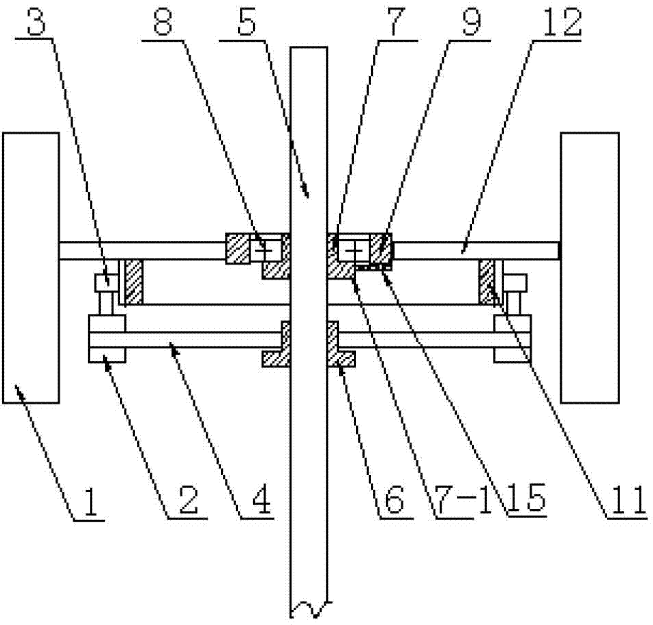
A kind of wind power generating set with vertical shaft
Technical field
The utility model relates to technical field of wind power generation, relates in particular to a kind of wind power generating set with vertical shaft.
Background technique
Wind-power electricity generation is the industry of at present the most ripe, on the largest scaleization of whole world technology aspect utilization of new energy resources and industrialized development, and along with the day by day lifting of environmental protection concept, the application of wind-power electricity generation is increasingly extensive.Present wind power generating set with vertical shaft generally is to adopt direct drive, and namely by wind energy conversion system rotating shaft and the generating of alternator shaft Driven by Coaxial, this structure remains in following defective: one is that a cover wind energy conversion system can only drive a generator job, and energy utilization rate is low; The 2nd, the rotating ratio that obtains from the wind energy conversion system rotating shaft is lower, need further machinery speed increasing or adopt multipolar generator, but electricity generation efficiency is not very desirable; The 3rd, install and to set up inconvenience, especially can't install a large amount of various king-posts of having set up, wind-driven generator is installed then is lost more than gain if destroy former tower column structure, so just greatly limited wind-driven generator in the application that has now on the king-post.In order to address this problem, people are the outside weldings carriage at original king-post at present, vertical axis aerogenerator is erected at the king-post periphery, owing to be subjected to the generated energy that this not only can not obtain relatively high power that limits of supporting structure, and can the stress balance of king-post be impacted, therefore using wind-power electricity generation for existing king-post does not still have better way at present, and the value of its king-post is not fully utilized.As being distributed in numerous communication king-post of regional, the cylinder of the large-scale king-post that it is set up in order to obtain height is in vacant state mostly, and the wind energy advantage in high-altitude there is no method utilized.
The model utility content
The utility model provides a kind of wind power generating set with vertical shaft for above-mentioned the deficiencies in the prior art.It not only can drive several generator operations with same wind energy conversion system, is conducive to the raising of generating efficiency, and can splice easily and be installed on the various existing king-posts.
The technological scheme that the utility model solves the problems of the technologies described above is as follows: a kind of wind power generating set with vertical shaft, comprise wind-drive mechanism and power facility, and it is characterized in that:
Described wind-drive mechanism comprises a plurality of fan blades, gear ring and fan blade supporting component, described fan blade supporting component comprises rotating cylinder, fixed cylinder and a plurality of strut, the outer cover of described fixed cylinder is equipped with bearing, described rotating cylinder is sleeved on the outside of described bearing, one end of described strut is fixedly connected on the outside of described rotating cylinder, the other end connects described fan blade, described a plurality of fan blade is distributed on the same circumference, described gear ring is fixed on described strut or the rotating cylinder, described gear ring and described rotating cylinder concentric.
Described power facility comprises generator, generator support and rack fixing seat, described rack fixing seat is cylindrical, one end of described generator support is fixedly connected on the described rack fixing seat, described generator is fixed on the other end of described generator support, be furnished with gear on the described alternator shaft, described gear is meshed with described gear ring.
The beneficial effects of the utility model are: owing to adopted at strut or rotating cylinder gear ring drive generator is set, its major advantage is and can drives a plurality of generators with same wind energy conversion system, unit generating than prior art can utilize wind energy greatly, in addition because the gear ratio gap of gear ring and generator gear is very large, therefore can make generator obtain very high rotating speed, obtain better generating efficiency.
On the basis of technique scheme, the utility model can also be done following improvement.
Further, described rotating cylinder, fixed cylinder, gear ring, bearing and rack fixing seat are the split type composite structure.Described split type structure refers to the cylindrical shells such as rotating cylinder, fixed cylinder, gear ring, bearing and rack fixing seat are radially split into along it and dissects part, each can form complete parts after dissecing the part combination, do not need to be sleeved on the installation shaft in installing at the scene, as long as then can around described installation shaft splicing installation.
Adopt the beneficial effect of above-mentioned further scheme to be, this split type composite structure has made things convenient for larger workpiece to make, more convenient Assembling, especially for existing king-post, can guarantee in the intact situation of original king-post that directly utilize existing king-post that wind-driven generator is installed, so not only convenient construction is installed, and greatly saved king-post and reproduced expense or recondition expense, so that existing various king-posts utilize powered by wind energy to become easier.
Further, the described parts that each has the split type composite structure combine by dissecing part more than two or two respectively.
Adopt the beneficial effect of above-mentioned further scheme to be, can determine to adopt two or three combinations according to the size of concrete parts.
Further, also be provided with the splicing clamping plate on described rotating cylinder, fixed cylinder, gear ring and the rack fixing seat.
Adopt the beneficial effect of above-mentioned further scheme to be, at peripheral components the assembly unit clamping plate are set, it is firm effectively each to be dissectd the part clamping.
Further, described fixed cylinder and rack fixing seat endoporus are straight tube shape or are the loudspeaker tubular of endoporus lower end diameter greater than upper end diameter.
Adopt the beneficial effect of above-mentioned further scheme to be, this structure is supporting for going up greatly little king-post under the common diameter.
Further, also be provided with braking mechanism between the rotating cylinder of described wind-drive mechanism and the fixed cylinder, described braking mechanism comprise brake and the brake pin, an end and the described fixed cylinder of described brake handle are articulated and connected, the other end is provided with pin-and-hole, and described brake pin is located on the described rotating cylinder.
Adopt the beneficial effect of above-mentioned further scheme to be, adopt braking mechanism when carrying out the cat head maintenance, to stop the wind energy conversion system running, to guarantee maintenance man's safety.
Further, described generator quantity is one or more, and described generator is multipolar generator.
Adopt the beneficial effect of above-mentioned further scheme to be, can the generator number be set according to the moment of wind energy conversion system and electric power etc., generally be preferably at least two to guarantee stress balance, also can be three, four or be equally spaced more.
Further, described gear ring is ring gear or external toothing.
Adopt the beneficial effect of above-mentioned further scheme to be, can select external toothing or ring gear according to the gear ring size.
Further, the bottom of described fixed cylinder is provided with outer rim, and described rotating cylinder top also is provided with guard shield.
Adopt the beneficial effect of above-mentioned further scheme to be, outer rim is established in the bottom of fixed cylinder can make support more stable, and guard shield then is conducive to the protection supported.
Further, described fan blade supporting component is provided with two groups up and down, and described bearing is tapered roller bearing.
Adopt the beneficial effect of above-mentioned further scheme to be, usually can adopt upper and lower two groups of fan blade supporting components for very long blade structure.
Description of drawings
Fig. 1 is structural representation of the present utility model;
Fig. 2 is the plan view of Fig. 1;
Fig. 3 is that rotating cylinder, fixed cylinder and bearing split into two-part and dissect the part structural representation among Fig. 1;
Fig. 4 is that rotating cylinder, fixed cylinder and bearing split into three parts and dissect the part structural representation among Fig. 1;
Fig. 5 is that rotating cylinder dissects the part structural representation after splitting among Fig. 3;
Fig. 6 is that fixed cylinder dissects the part structural representation after splitting among Fig. 3;
Fig. 7 dissects the part structural representation after Fig. 3 middle (center) bearing splits;
Fig. 8 dissects the part structural representation after gear ring splits;
Fig. 9 is the local enlarged diagram of braking mechanism among Fig. 1;
Figure 10 is that fixed cylinder and rack fixing seat endoporus are the mounting structure schematic representation of loudspeaker tubular;
Figure 11 is that gear ring is fixed on the mounting structure schematic representation on the rotating cylinder;
Figure 12 is that generator is at gear ring inner mesh structural representation;
Figure 13 is provided with up and down the utility model structural representation of two groups of fan blade supporting components.
In Figure 13, the represented list of designations of each label is as follows at Fig. 1: 1, fan blade, 2, generator, 3, gear, 4, generator support, 5, king-post, 6, rack fixing seat, 7, fixed cylinder, 7-1, outer rim, 8, bearing, 9, rotating cylinder, 10, guard shield, 11, gear ring, 12, strut, 13, splicing seams, 14, the splicing clamping plate, 15, braking mechanism, 15-1, brake pin, 15-2, hinging shaft, 15-3, brake handle.
Embodiment
Below in conjunction with accompanying drawing principle of the present utility model and feature are described, institute gives an actual example and only is used for explaining the utility model, is not be used to limiting scope of the present utility model.
Arrive shown in Figure 8 such as Fig. 1, a kind of wind power generating set with vertical shaft, comprise wind-drive mechanism and power facility, described wind-drive mechanism comprises a plurality of fan blades 1, gear ring 11 and fan blade supporting component, described fan blade supporting component comprises rotating cylinder 9, fixed cylinder 7 and a plurality of strut 12, the outer cover of described fixed cylinder 7 is equipped with bearing 8, described rotating cylinder 9 is sleeved on the outside of described bearing 8, one end of described strut 12 is fixedly connected on the outside of described rotating cylinder 9, the other end connects described fan blade 1, described a plurality of fan blade 1 is distributed on the same circumference, described gear ring 11 is fixed on the described strut 12, described gear ring 11 and described rotating cylinder 9 concentrics;
Described power facility comprises generator 2, generator support 4 and rack fixing seat 6, described rack fixing seat 6 is cylindrical, one end of described generator support 4 is fixedly connected on the described rack fixing seat 6, described generator 2 is fixed on the other end of described generator support 4, be furnished with gear 3 in described generator 2 rotating shafts, described gear 3 is meshed with described gear ring 11.
Described rotating cylinder 9, fixed cylinder 7, gear ring 11, bearing 8 and rack fixing seat 6 are the split type composite structure.Described split type structure refers to the parts such as rotating cylinder 9, fixed cylinder 7, gear ring 11, bearing 8 and rack fixing seat 6 are radially split into along it and dissects part, each can form complete parts after dissecing the part combination, do not need to be sleeved on the installation shaft in installing at the scene, as long as splicing install then can, the parts after combination form splicing seams 13.Installation shaft described here is king-post 5.Specifically on-the-spot described fixed cylinder 7 splicings are fixed on the described king-post 5, described bearing 8, rotating cylinder 9 are spliced and be sleeved on the outside of described fixed cylinder 7 successively, described rack fixing seat 6 is also spliced on described king-post 5; After strut 12 installed, gear ring 11 splicings also were fixed on the described strut 12, and guarantee described gear ring 11 and described rotating cylinder 9 concentrics.
The described parts that each has the split type composite structure combine by dissecing part more than two or two respectively.Generally can select two lobes, three lobes or pintongs to dissect the part combination, be as the criterion to be fit to fabrication and installation.
Also be provided with splicing clamping plate 14 on described rotating cylinder 9, fixed cylinder 7, gear ring 11 and the rack fixing seat 6.
Described fixed cylinder 7 and rack fixing seat 6 endoporus are straight tube shape.
Described generator 2 quantity are one or more, are provided with 4 generators in this example.Described generator 2 is multipolar generator.
Described gear ring 11 is external toothing.
The bottom of described fixed cylinder 7 is provided with outer rim 7-1, and described rotating cylinder 9 tops also are provided with guard shield 10.
Described bearing 8 is tapered roller bearing or thrust-bearing.
Be illustrated in figure 9 as braking mechanism 15 schematic representation.Also be provided with braking mechanism 15 between the rotating cylinder 9 of described wind-drive mechanism and the fixed cylinder 7, described braking mechanism 15 comprises that brake is 15-3 and a plurality of brake pin 15-1, described brake is articulated and connected the end of 15-3 and described fixed cylinder 7, the other end is provided with pin-and-hole, and described brake pin 15-1 is located on the described rotating cylinder 9.Namely described brake can along described fixed cylinder 7 hinging shaft 15-2 upset downwards, be lifted 15-3 brake and be socketed on the described bearing pin 15-3 and with pin-and-hole during use under normal circumstances.
Be that fixed cylinder 7 and rack fixing seat 6 endoporus are the mounting structure schematic representation of loudspeaker tubular as shown in figure 10; Described fixed cylinder 7 and rack fixing seat 6 endoporus are that lower end diameter is greater than the loudspeaker tubular of upper end diameter.This structure is conducive to install at taper king-post 5.Also can adopt the form that in described straight tube shape fixed cylinder and rack fixing seat 6, adds in addition the Megaphone annex to install.
Be that gear ring 11 is fixed on the mounting structure schematic representation on the rotating cylinder 9 as shown in figure 11; This structure more is conducive to gear ring 11 smooth runnings.
Be that generator 2 is at gear ring 11 inner mesh structural representations as shown in figure 12; Be that described gear ring 11 is ring gear.
As shown in figure 13 for being provided with up and down the utility model structural representation of two groups of fan blade supporting components.Described fan blade supporting component is provided with upper and lower two groups.This structure relatively is suitable for the fixed installation of long fan blade.For higher king-post 5, multistage wind generating unit of the present utility model can also be installed.
The utility model in the specific implementation, can determine according to concrete king-post 5 sizes the processing dimension of associated components, also can adopt the mode that in fixed cylinder 7 and rack fixing seat 6, adds in addition auxiliary installation piece, as for the less truss structure pylon of cross-section size, also can in described fixed cylinder 7 and rack fixing seat 6, set up and the matched supporting element of described pylon, make circular cylinder body of the peripheral formation of pylon, and then wind generating unit of the present utility model is installed.
The above only is preferred embodiment of the present utility model, and is in order to limit the utility model, not all within spirit of the present utility model and principle, any modification of doing, is equal to replacement, improvement etc., all should be included within the protection domain of the present utility model.