CN202726427U - Automatic assembly device for temperature wrap clamps - Google Patents
Automatic assembly device for temperature wrap clamps Download PDFInfo
- Publication number
- CN202726427U CN202726427U CN 201220377298 CN201220377298U CN202726427U CN 202726427 U CN202726427 U CN 202726427U CN 201220377298 CN201220377298 CN 201220377298 CN 201220377298 U CN201220377298 U CN 201220377298U CN 202726427 U CN202726427 U CN 202726427U
- Authority
- CN
- China
- Prior art keywords
- temperature
- cylinder
- double team
- sensitive double
- casting die
- Prior art date
- Legal status (The legal status is an assumption and is not a legal conclusion. Google has not performed a legal analysis and makes no representation as to the accuracy of the status listed.)
- Expired - Lifetime
Links
Images


Abstract
The utility model relates to an automatic assembly device for temperature wrap clamps. The automatic assembly device comprises two mounting baseplates, a punch pin and a fixing seat with a temperature wrap clamp fixing groove, wherein a feeding and sequencing mechanism, a clamping and conveying mechanism, a direction identifying and correcting mechanism and a pressing mechanism are fixedly arranged on the two mounting baseplates respectively; the temperature wrap clamps are continuously and automatically fed to the ends of feeding guide rails through the feeding and sequencing mechanism; the temperature wrap clamp at the tail ends of the feeding guide rails and the temperature wrap clamp in a rotary fixing groove are respectively clamped and placed in the rotary fixing groove in the direction identifying and correcting mechanism and the temperature wrap clamp fixing groove in the pressing mechanism by the clamping and conveying mechanism; the direction identifying and correcting mechanism is used for correcting the assembly direction of the temperature wrap clamp which is clamped and conveyed into the rotary fixing groove by the clamping and conveying mechanism; the pressing mechanism is used for expanding the inner hole of the temperature wrap clamp; and a temperature wrap head is inserted into the inner hole of the temperature wrap clamp by an operator, so as to finish the assembly of the temperature wrap clamp. The automatic assembly device is simple in structure, realizes automatic assembly, fundamentally changes the original situation of manually assembly the temperature wrap clamps, improves the assembly efficiency of the temperature wrap clamps, prevents the temperature wrap clamps from being damaged, and reduces the production cost.
Description
Technical field
The utility model relates to a kind of assembly equipment of assembly, particularly a kind of temperature-sensitive double team automatic assembling apparatus.
Background technology
The temperature-sensitive double team is equiped with a temperature-sensitive packet header as a kind of stamping parts in its endoporus, use in the outdoor machine of air-conditioner, and temperature-sensitive packet header is mounted with in a certain position.The assembling of temperature-sensitive double team is that temperature-sensitive packet header is inserted in the endoporus of temperature-sensitive double team, and spacing by the punching press convex closure of temperature-sensitive double team endoporus edge, the inwall elastical retraction power of temperature-sensitive double team is fixedly clamped temperature-sensitive packet header cylindrical.Because temperature-sensitive packet header external diameter is than the large 0.2mm of temperature-sensitive double team endoporus, so just can not directly take the assembling of temperature-sensitive packet header to be inserted in the endoporus of temperature-sensitive double team by manual.For this problem, mostly designed an easy pressure sensitivity thermometer bulb folder frock, the support, the handle that comprise drift, band grain, by the manual temperature-sensitive double team of taking, put it into inwardly in the support groove by the punching press convex closure, push down temperature-sensitive double team inboard downwards by the manual handle drive drift of pressing again, and its diameter of bore swollen, temperature-sensitive packet header of taking by hand is inserted in the temperature-sensitive double team endoporus, and it is spacing to withstand the punching press convex closure, and release handle has just been finished the assemble flow of 1 temperature-sensitive double team again.This temperature-sensitive double team assembly work needs at least two operating personnel's manual operationss just can finish, and hand assembled temperature-sensitive double team, by the placing direction of per 1 the temperature-sensitive double team of manual identified, manual temperature-sensitive double team, manual handle, the manual temperature-sensitive packet header of inserting of pressing of placing, cause production efficiency low, the stroke that drift presses down can not be spacing, may cause the temperature-sensitive double team to be damaged by pressure.
Summary of the invention
The purpose of this utility model is to overcome the deficiencies in the prior art, a kind of temperature-sensitive double team automatic assembling apparatus is provided, it is simple in structure, realization automation assembling, fundamentally change original situation by manual assembly temperature-sensitive double team, improve the efficiency of assembling of temperature-sensitive double team, avoid the temperature-sensitive double team to be damaged by pressure, reduce production costs.
The utility model has adopted following technical scheme: a kind of temperature-sensitive double team automatic assembling apparatus, and include two mounting bases, drift, fix the holder of grain with the temperature-sensitive double team, it is characterized in that:
1), on aforesaid two mounting bases, is installed with respectively feed and ordering mechanism, clamping and feed mechanism, direction identification and aligning gear and casting die mechanism;
2), aforementioned feed and the peaceful device that shakes of ordering mechanism's involving vibrations dish, the peaceful device that shakes of vibrating disk is installed in respectively on the first mounting base and the second mounting base, two feed guide rails are arranged at the top at the flat device that shakes, lateral surface and upper plane at the first feed guide rail end are respectively arranged with the first Fibre Optical Sensor and the second Fibre Optical Sensor, article two, the right-hand member of feed guide rail docks with the delivery outlet of vibrating disk, and the end of two feed guide rail left ends is provided with the supplied materials baffle plate;
3), aforementioned clamping and feed mechanism have the lift cylinder that vertically is located on the second mounting base, on this lift cylinder expansion link the lifting fixed head is arranged, each vertically is provided with a fixed head two ends of lifting fixed head, the promotion cylinder is arranged on the fixed head of one end, laterally be provided with side by side two sliding axles between two fixed heads, slidely connect slide block on the sliding axle, one end of slide block is connected with the expansion link that promotes cylinder, be provided with side by side the first cylinder and the second cylinder on the slide block, the telescopic rod end of two cylinders is installed with respectively the first impeller-hub fixed head and the second impeller-hub fixed head, be installed with side by side respectively two the first chuck impeller-hubs and the second chuck impeller-hub on the two impeller-hub fixed heads, the other end of two chuck impeller-hubs passes slide block, be connected with the first chuck that laterally is set up in parallel and the second chuck respectively, the right-hand member of two chucks is corresponding up and down with aforementioned feed guide rail left end;
4), aforementioned direction identification has an oscillating cylinder with aligning gear, this oscillating cylinder is connected through a L shaped oscillating cylinder fixed head and described the second mounting base, the cylinder axle head of oscillating cylinder is installed with rotating fixed disk, there is the fixing grain of rotation this rotating fixed disk upper surface, and the first chuck in aforementioned clamping and the feed mechanism and the left end of the second chuck and rotation are fixing corresponding about poor;
5), there is the door shape casting die cylinder fixed mount that is installed on the second mounting base in aforementioned casting die mechanism, vertically be provided with the casting die cylinder on the crossbeam of this casting die cylinder fixed mount, the casting die Telescopic-cylinder boom end that passes crossbeam sets firmly described drift, set firmly described holder with the fixing grain of temperature-sensitive double team with drift is coaxial on mounting base, aforesaid casting die cylinder is connected with the control gas circuit of the control cabinet of peripheral hardware.
The both sides of the lift cylinder in front fan's clamping and feed mechanism are arranged with the lifting sliding axle in parallel with lift cylinder, and aforementioned lifting fixed head is passed in the upper end of this lifting sliding axle, and lifting sliding axle and lifting fixed head are slidingly connected.
The holder top with the fixing grain of temperature-sensitive double team in aforementioned casting die mechanism, the right-hand member of the fixing grain of temperature-sensitive double team is provided with fixing poor baffle plate, is provided with the 3rd Fibre Optical Sensor at this fixing poor baffle plate, and the 3rd Fibre Optical Sensor is electrically connected with the control cabinet of peripheral hardware.
The two ends of the drift in aforementioned casting die mechanism are provided with the deflector apron that the inboard, lower end is an inclined-plane.
The temperature-sensitive double team automatic assembling apparatus that provides by the utility model, when carrying out temperature-sensitive double team production assembling, the source of the gas of the cylinder in each organisation of working be connected the power supply of part and be connected with the automatic assembling apparatus control cabinet of peripheral hardware, the temperature-sensitive double team is put into the vibrating disk of feed and ordering mechanism, vibration auto-sequencing by vibrating disk is fed on the feed guide rail of the flat device that shakes, and the flat device vibration of shaking is delivered to feed guide rail end continuously automatically with the temperature-sensitive double team.Be installed in the first Fibre Optical Sensor on the feed guide rail and whether be responsible for responding to supplied materials, be responsible for responding to the breach direction of temperature-sensitive double team by the second Fibre Optical Sensor, confirm whether direction and assembly direction that the temperature-sensitive double team come by vibration feeding be reverse.
When the first Fibre Optical Sensor is sensed supplied materials, expansion link by the second cylinder in clamping and the feed mechanism stretches out promotion the second impeller-hub fixed head, driving the second chuck impeller-hub moves, thereby drive the lateral movement that makes progress of the second chuck, the expansion link of the first cylinder is retracted and is spurred the first impeller-hub fixed head simultaneously, driving the first chuck impeller-hub moves, thereby drive the downward lateral movement of the first chuck, by the aggregate motion of two chucks, the holding action when two ends of two chucks have just been finished the temperature-sensitive double team in the fixing grain of rotation in the temperature-sensitive double team of feed guide rail end and direction identification and the aligning gear.Stretched out by the expansion link of lift cylinder the lifting fixed head is risen, thereby the slide block on the lifting fixed head and two cylinders, two parts such as chuck are risen, the expansion link that promotes cylinder stretches out and promotes slide block and slide left and put in place, the lifting fixed head is fallen in expansion link retraction by lift cylinder, thus just simultaneously with the temperature-sensitive double team of feed guide rail end and the temperature-sensitive double team in the fixing grain of rotation, clamping is put in direction identification and the fixing grain of the rotation in the aligning gear and in the temperature-sensitive double team holddown groove in the casting die mechanism respectively; Retracted by the expansion link of the second cylinder again and spur the second impeller-hub fixed head, driving the second chuck impeller-hub moves, thereby drive the downward lateral movement of the second chuck, the expansion link of the first cylinder stretches out and promotes the first impeller-hub fixed head simultaneously, driving the first chuck impeller-hub moves, thereby drive the lateral movement that makes progress of the first chuck, aggregate motion by two chucks, just finished the action of unclamping to the temperature-sensitive double team, subsequently, the expansion link retraction pulling slide block that promotes cylinder slides into the feed guide rail end to the right, thereby finished the circulation of an action, waited for again clamping temperature-sensitive double team work, adopted automatic telescopic and the double collet structure of two cylinders, realized to the automatic clamping of temperature-sensitive double team with unclamp and a gripping and the supplied materials that unclamps double.
There is non-notch top by the second Fibre Optical Sensor induction temperature-sensitive double team, if sense breach, illustrate that induction double team supplied materials direction at this moment is opposite with assembly direction, this signal rotates to the oscillating cylinder in identification and the aligning gear through external control case controlling party, drive the rotating fixed disk that the cylinder axle head sets firmly, and the fixing poor 180 degree rotations of doing of the rotation on this rotating fixed disk, fix the assembly direction of the induction double team in the grain to delivered to rotation by clamping and feed mechanism clamping and proofread and correct; If the second Fibre Optical Sensor is sensed the top non-notch of temperature-sensitive double team, illustrate that the supplied materials direction of induction double team this moment is identical with assembly direction, deliver to induction double team in the fixing grain of rotation by clamping and feed mechanism clamping and do not do 180 and spend and rotate.Owing to adopted the automatic detection identification of Fibre Optical Sensor to the temperature-sensitive double team, realized the automatic rotation calibration function of temperature-sensitive double team assembling direction of insertion.
To being delivered to by clamping and feed mechanism clamping in the temperature-sensitive double team holddown groove in the casting die mechanism, the temperature-sensitive double team that assembly direction is correct, the expansion link of the casting die cylinder on the peripheral control box control casting die cylinder fixed mount stretches out, driving drift on it pushes down the temperature-sensitive double team and temperature-sensitive double team endoporus is enlarged, by the operator temperature-sensitive packet header is inserted in the temperature-sensitive double team endoporus, and withstand the spacing convex closure of punching press on the temperature-sensitive double team, after sensing temperature-sensitive packet header end face by the 3rd Fibre Optical Sensor, the expansion link retraction of the control cabinet control casting die cylinder of peripheral hardware, the temperature-sensitive double team is clamped in temperature-sensitive packet header in its endoporus, the operator just can take off the temperature-sensitive double team that assembles temperature-sensitive packet header, device will repeat above action and carry out assembling next time, realized drift automatically pushing down the temperature-sensitive double team, hole dimension in the temperature-sensitive double team is enlarged, the automatic induction that temperature-sensitive packet header plug-in mounting puts in place, convenient operation personnel's assembling is inserted.
The utility model is simple in structure, has realized the automation assembling, fundamentally changes original situation by manual assembly temperature-sensitive double team, become one man operation by original two people operation, improve the efficiency of assembling of temperature-sensitive double team, avoided the temperature-sensitive double team to be damaged by pressure, reduced production cost.
Description of drawings
The utility model said structure can further specify by the non-limiting embodiment that accompanying drawing provides.
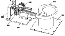
Fig. 1 is structural representation of the present utility model;
Fig. 2 is schematic rear view of the present utility model;
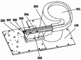
Fig. 3 is the structural representation of feed and ordering mechanism;
Fig. 4 is the schematic diagram of clamping and feed mechanism;
Fig. 5 is the rearview of Fig. 4;
Fig. 6 is Fig. 5 top view;
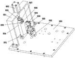
Fig. 7 is the schematic diagram of direction identification and aligning gear and casting die mechanism;
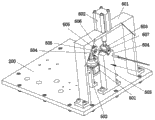
Fig. 8 is the left view of Fig. 7;
Fig. 9 is feed guide rail, direction identification and aligning gear and the schematic diagram of fixing the holder of grain with the temperature-sensitive double team.
The specific embodiment
Embodiment of the present utility model is described with reference to the accompanying drawings.In the embodiment of Fig. 1-shown in Figure 9, a kind of temperature-sensitive double team automatic assembling apparatus, include two mounting bases 100,200, drift 603, fix the holder 604 of grain with the temperature-sensitive double team, on aforesaid two mounting bases 100,200, be installed with respectively feed and ordering mechanism 300, clamping and feed mechanism 400, direction identification and aligning gear 500 and casting die mechanism 600; Aforementioned feed and ordering mechanism 300 involving vibrations dishes, the 301 peaceful devices 302 that shake, vibrating disk 301) the peaceful device 302 that shakes is installed in respectively on the first mounting base 100 and the second mounting base 200, two feed guide rails 303,304 are arranged at the top at the flat device that shakes, lateral surface and upper plane at the first feed guide rail 303 ends are respectively arranged with the first Fibre Optical Sensor 305 and the second Fibre Optical Sensor 306, article two, feed guide rail 303,304 right-hand member dock with the delivery outlet of vibrating disk 301, and the end of two feed guide rails 303,304 left ends is provided with supplied materials baffle plate 307; Aforementioned clamping and feed mechanism 400 have the lift cylinder 401 that vertically is located on the second mounting base on 200, on this lift cylinder expansion link lifting fixed head 402 is arranged, each vertically is provided with a fixed head 403 two ends of lifting fixed head, the cylinder 404 of promotion is arranged on the fixed head of one end, laterally be provided with side by side two sliding axles 405 between two fixed heads 403, slidely connect slide block 406 on the sliding axle, one end of slide block is connected with the expansion link that promotes cylinder 404, be provided with side by side the first cylinder 407 and the second cylinder 408 on the slide block, two cylinders 407,408 telescopic rod end is installed with respectively the first impeller-hub fixed head 409 and the second impeller-hub fixed head 410, two impeller-hub fixed heads 409, be installed with side by side respectively two the first chuck impeller-hubs 411 and the second chuck impeller-hub 412 on 410, two chuck impeller-hubs 411,412 the other end passes slide block 406, be connected two chucks 413 with the first chuck 413 that laterally is set up in parallel and the second chuck 414 respectively, 414 right-hand member is corresponding up and down with aforementioned feed guide rail left end; Aforementioned direction identification has an oscillating cylinder 501 with aligning gear 500, this oscillating cylinder is connected with described the second mounting base 200 through a L shaped oscillating cylinder fixed head 502, the cylinder axle head of oscillating cylinder is installed with rotating fixed disk 503, there is the fixing grain 504 of rotation this rotating fixed disk upper surface, the fixing poor two ends of this rotation are provided with rotation plate washer 505, and the first chuck 413 in aforementioned clamping and the feed mechanism 400 and the left end of the second chuck 414 are fixed poor corresponding about in the of 504 with rotation; There is the door shape casting die cylinder fixed mount 601 that is installed on the second mounting base 200 in aforementioned casting die mechanism 600, vertically be provided with casting die cylinder 602 on the crossbeam of this casting die cylinder fixed mount, the casting die Telescopic-cylinder boom end that passes crossbeam sets firmly described drift 603, set firmly described holder 604 with the fixing grain of temperature-sensitive double team with drift 603 is coaxial on mounting base, aforesaid casting die cylinder 602 is connected with the control gas circuit of the control cabinet of peripheral hardware.Vibrating disk adopts the SF-300 vibrating disk; The flat device that shakes adopts the flat vibrator that send of SF-300; The puzzled device of first, second optical fiber transmission adopts the FU-35FA Fibre Optical Sensor; Lift cylinder adopts SDA S-32X15 thin cylinder; Promote cylinder and adopt SDA S-32X75 thin cylinder; First, second cylinder adopts SDA S-32X10 thin cylinder; Oscillating cylinder adopts the MDSUB3-180S-K23 oscillating cylinder; The casting die cylinder adopts SDA S-32X40 thin cylinder.Each cylinder is connected with the control gas circuit of the control cabinet of peripheral hardware respectively, and vibrating disk, flat device and the puzzled device of first, second optical fiber transmission of shaking are electrically connected with the control cabinet of peripheral hardware respectively.
In Fig. 1, Fig. 2, embodiment shown in Figure 5, the both sides of the lift cylinder 401 in front fan's clamping and feed mechanism 400, be arranged with lifting sliding axle 415 in parallel with lift cylinder 401, aforementioned lifting fixed head 402 is passed in the upper end of this lifting sliding axle, and lifting sliding axle 415 is slidingly connected with lifting fixed head 402.The setting of this lifting sliding axle is convenient to the lifting fixed head and slides more effective maintenance lifting fixed head lifting exactly along two lifting sliding axles under the promotion of lift cylinder.
In Fig. 7, embodiment shown in Figure 9, holder 604 tops with the fixing grain of temperature-sensitive double team in aforementioned casting die mechanism 600, the right-hand member of the fixing grain of temperature-sensitive double team is provided with fixing poor baffle plate 605, being provided with the 3rd Fibre Optical Sensor 606, the three Fibre Optical Sensors at this fixing poor baffle plate is electrically connected with the control cabinet of peripheral hardware.Whether put in place by the 3rd Fibre Optical Sensor induction temperature-sensitive packet header end face, withstood the spacing convex closure of punching press on the temperature-sensitive double team, after the 3rd Fibre Optical Sensor is sensed the spacing convex closure of punching press that temperature-sensitive packet header end face pushes up the temperature-sensitive double team, peripheral control box control casting die cylinder drives drift and regains, further guarantee the assembly quality of temperature-sensitive double team, the 3rd Fibre Optical Sensor adopts FU-35FA optical fiber prisoner sensor.
In Fig. 7, embodiment shown in Figure 8, the two ends of the drift 603 in aforementioned casting die mechanism 600 are provided with the deflector apron 607 that the inboard, lower end is an inclined-plane.When drift presses down, by set deflector apron, the two ends of temperature-sensitive double team are pushed down on the inclined-plane of its lower end, to by the first chuck in clamping and the feed mechanism, the second chuck left end, from the rotation fixing grain 504 temperature-sensitive double team guide-localizations that are sent to casting die mechanism 600 of direction identification with aligning gear 500, the temperature-sensitive double team is not offset.
Above-described embodiment also only is for explanation the utility model, is not to restriction of the present utility model, to improvement of the present utility model, all belongs to the scope of the utility model claim protection under design prerequisite of the present utility model.
Claims (4)
1. a temperature-sensitive double team automatic assembling apparatus includes two mounting bases (100,200), drift (603), fixes the holder (604) of grain with the temperature-sensitive double team, it is characterized in that:
1), on aforesaid two mounting bases (100,200), is installed with respectively feed and ordering mechanism (300), clamping and feed mechanism (400), direction identification and aligning gear (500) and casting die mechanism (600);
2), aforementioned feed and ordering mechanism (300) involving vibrations dish (301) the peaceful devices that shake (302), the peaceful device that shakes of vibrating disk (301) (302) is installed in respectively on the first mounting base (100) and the second mounting base (200), two feed guide rails (303 are arranged at the top at the flat device that shakes, 304), lateral surface and the upper plane terminal at the first feed guide rail (303) are respectively arranged with the first Fibre Optical Sensor (305) and the second Fibre Optical Sensor (306), article two, feed guide rail (303,304) right-hand member docks with the delivery outlet of vibrating disk (301), two feed guide rails (303,304) end of left end is provided with supplied materials baffle plate (307);
3), aforementioned clamping and feed mechanism (400) have the lift cylinder (401) that vertically is located on the second mounting base (200), lifting fixed head (402) is arranged on this lift cylinder expansion link, each vertically is provided with a fixed head (403) two ends of lifting fixed head, promotion cylinder (404) is arranged on the fixed head of one end, laterally be provided with side by side two sliding axles (405) between two fixed heads (403), slidely connect slide block (406) on the sliding axle, one end of slide block is connected with the expansion link that promotes cylinder (404), be provided with side by side the first cylinder (407) and the second cylinder (408) on the slide block, two cylinders (407,408) telescopic rod end is installed with respectively the first impeller-hub fixed head (409) and the second impeller-hub fixed head (410), two impeller-hub fixed heads (409,410) be installed with side by side respectively two the first chuck impeller-hubs (411) and the second chuck impeller-hub (412) on, two chuck impeller-hubs (411,412) the other end passes slide block (406), be connected two chucks (413 with the first chuck (413) that laterally is set up in parallel and the second chuck (414) respectively, 414) right-hand member is corresponding up and down with aforementioned feed guide rail left end;
4), aforementioned direction identification has an oscillating cylinder (501) with aligning gear (500), this oscillating cylinder is connected through a L shaped oscillating cylinder fixed head (502) and described the second mounting base (200), the cylinder axle head of oscillating cylinder is installed with rotating fixed disk (503), there is the fixing grain of rotation (504) this rotating fixed disk upper surface, the fixing poor two ends of this rotation are provided with rotation plate washer (505), the first chuck (413) in aforementioned clamping and the feed mechanism (400) and the left end of the second chuck (414) with rotate that to fix poor (504) corresponding up and down;
5), there is the door shape casting die cylinder fixed mount (601) that is installed on the second mounting base (200) in aforementioned casting die mechanism (600), vertically be provided with casting die cylinder (602) on the crossbeam of this casting die cylinder fixed mount, the casting die Telescopic-cylinder boom end that passes crossbeam sets firmly described drift (603), set firmly described holder (604) with the fixing grain of temperature-sensitive double team with drift (603) is coaxial on mounting base, aforesaid casting die cylinder (602) is connected with the control gas circuit of the control cabinet of peripheral hardware.
2. a kind of temperature-sensitive double team automatic assembling apparatus according to claim 1, the both sides that it is characterized in that the lift cylinder (401) in front fan's clamping and feed mechanism (400), be arranged with lifting sliding axle (415) in parallel with lift cylinder (401), aforementioned lifting fixed head (402) is passed in the upper end of this lifting sliding axle, and lifting sliding axle (415) is slidingly connected with lifting fixed head (402).
3. a kind of temperature-sensitive double team automatic assembling apparatus according to claim 1, it is characterized in that holder (604) top with the fixing grain of temperature-sensitive double team in aforementioned casting die mechanism (600), the right-hand member of the fixing grain of temperature-sensitive double team is provided with fixing poor baffle plate (605), be provided with the 3rd Fibre Optical Sensor (606) at this fixing poor baffle plate, the 3rd Fibre Optical Sensor is electrically connected with the control cabinet of peripheral hardware.
4. according to claim 1 or 3 described a kind of temperature-sensitive double team automatic assembling apparatus, it is characterized in that the two ends of the drift (603) in aforementioned casting die mechanism (600) are provided with the deflector apron that the inboard, lower end is an inclined-plane (607).
Priority Applications (1)
| Application Number | Priority Date | Filing Date | Title |
|---|---|---|---|
| CN 201220377298 CN202726427U (en) | 2012-08-01 | 2012-08-01 | Automatic assembly device for temperature wrap clamps |
Applications Claiming Priority (1)
| Application Number | Priority Date | Filing Date | Title |
|---|---|---|---|
| CN 201220377298 CN202726427U (en) | 2012-08-01 | 2012-08-01 | Automatic assembly device for temperature wrap clamps |
Publications (1)
| Publication Number | Publication Date |
|---|---|
| CN202726427U true CN202726427U (en) | 2013-02-13 |
Family
ID=47652176
Family Applications (1)
| Application Number | Title | Priority Date | Filing Date |
|---|---|---|---|
| CN 201220377298 Expired - Lifetime CN202726427U (en) | 2012-08-01 | 2012-08-01 | Automatic assembly device for temperature wrap clamps |
Country Status (1)
| Country | Link |
|---|---|
| CN (1) | CN202726427U (en) |
Cited By (17)
| Publication number | Priority date | Publication date | Assignee | Title |
|---|---|---|---|---|
| CN103673908A (en) * | 2013-12-23 | 2014-03-26 | 江苏理工学院 | Detection device and detection method for size of automatic through hole |
| CN105921975A (en) * | 2016-06-28 | 2016-09-07 | 吴中区木渎蒯斌模具加工厂 | Water spacing ring supply device of travel switch bottom assembler |
| CN105945551A (en) * | 2016-06-28 | 2016-09-21 | 吴中区木渎蒯斌模具加工厂 | Water-proof ring charging mechanism of travel switch bottom assembly machine |
| CN106040951A (en) * | 2016-07-12 | 2016-10-26 | 苏州瑞玛金属成型有限公司 | Automatic equipment for intra-mould riveting of stamping products |
| CN106078146A (en) * | 2016-08-11 | 2016-11-09 | 苏州市吴中区胥口健浩五金加工厂 | The limit assembly of electromagnetic valve diaphragm kludge |
| CN106077948A (en) * | 2016-08-30 | 2016-11-09 | 南京万舟发机电科技有限公司 | A kind of casing of lithium ion battery cutter sweep |
| CN106271576A (en) * | 2016-09-21 | 2017-01-04 | 深圳市深科特自动化科技有限公司 | Automatic locking screw machine |
| CN106378604A (en) * | 2016-11-21 | 2017-02-08 | 苏州鑫润旺精密机械有限公司 | Connecting shaft discharging device of crankshaft and connecting rod assembling machine |
| CN106876127A (en) * | 2017-04-20 | 2017-06-20 | 安徽预立兴川机器人技术有限公司 | A kind of transformer device is automatically positioned clamping mechanism |
| CN107303638A (en) * | 2016-04-17 | 2017-10-31 | 杨四清 | A kind of valve handle automatic charging recognizes press-in device |
| CN108454118A (en) * | 2018-04-09 | 2018-08-28 | 河北科技大学 | A kind of suspension floor bolster automatic installation apparatus |
| CN108687500A (en) * | 2018-06-28 | 2018-10-23 | 郑州云海信息技术有限公司 | A kind of pin type connector terminal discriminating device |
| CN108747359A (en) * | 2018-08-16 | 2018-11-06 | 苏州宜广科技有限公司 | The glue core feed mechanism of power interface assembling test equipment |
| CN109078865A (en) * | 2018-08-16 | 2018-12-25 | 苏州宜广科技有限公司 | Power interface assembling test equipment |
| CN110814679A (en) * | 2018-08-13 | 2020-02-21 | 福建德丰智能装备有限公司 | Second axis direction recognition mechanism |
| CN113714784A (en) * | 2021-09-18 | 2021-11-30 | 上海似锦发夹有限公司 | Hair inserting clip device |
| CN115072051A (en) * | 2022-07-06 | 2022-09-20 | 珠海格力智能装备有限公司 | Transfer equipment |
-
2012
- 2012-08-01 CN CN 201220377298 patent/CN202726427U/en not_active Expired - Lifetime
Cited By (23)
| Publication number | Priority date | Publication date | Assignee | Title |
|---|---|---|---|---|
| CN103673908A (en) * | 2013-12-23 | 2014-03-26 | 江苏理工学院 | Detection device and detection method for size of automatic through hole |
| CN107303638A (en) * | 2016-04-17 | 2017-10-31 | 杨四清 | A kind of valve handle automatic charging recognizes press-in device |
| CN105945551B (en) * | 2016-06-28 | 2018-07-17 | 和县新拓工业设计有限公司 | The water proof circle feed mechanism of travel switch bottom kludge |
| CN105921975A (en) * | 2016-06-28 | 2016-09-07 | 吴中区木渎蒯斌模具加工厂 | Water spacing ring supply device of travel switch bottom assembler |
| CN105945551A (en) * | 2016-06-28 | 2016-09-21 | 吴中区木渎蒯斌模具加工厂 | Water-proof ring charging mechanism of travel switch bottom assembly machine |
| CN106040951A (en) * | 2016-07-12 | 2016-10-26 | 苏州瑞玛金属成型有限公司 | Automatic equipment for intra-mould riveting of stamping products |
| CN106078146A (en) * | 2016-08-11 | 2016-11-09 | 苏州市吴中区胥口健浩五金加工厂 | The limit assembly of electromagnetic valve diaphragm kludge |
| CN106077948A (en) * | 2016-08-30 | 2016-11-09 | 南京万舟发机电科技有限公司 | A kind of casing of lithium ion battery cutter sweep |
| CN106077948B (en) * | 2016-08-30 | 2018-08-07 | 南京万舟发机电科技有限公司 | A kind of casing of lithium ion battery cutter device |
| CN106271576A (en) * | 2016-09-21 | 2017-01-04 | 深圳市深科特自动化科技有限公司 | Automatic locking screw machine |
| CN106378604A (en) * | 2016-11-21 | 2017-02-08 | 苏州鑫润旺精密机械有限公司 | Connecting shaft discharging device of crankshaft and connecting rod assembling machine |
| CN106876127B (en) * | 2017-04-20 | 2018-04-03 | 安徽预立兴川机器人技术股份有限公司 | A kind of transformer device is automatically positioned clamping mechanism |
| CN106876127A (en) * | 2017-04-20 | 2017-06-20 | 安徽预立兴川机器人技术有限公司 | A kind of transformer device is automatically positioned clamping mechanism |
| CN108454118A (en) * | 2018-04-09 | 2018-08-28 | 河北科技大学 | A kind of suspension floor bolster automatic installation apparatus |
| CN108454118B (en) * | 2018-04-09 | 2023-05-26 | 河北科技大学 | Automatic installation equipment for suspension floor buffer parts |
| CN108687500A (en) * | 2018-06-28 | 2018-10-23 | 郑州云海信息技术有限公司 | A kind of pin type connector terminal discriminating device |
| CN110814679A (en) * | 2018-08-13 | 2020-02-21 | 福建德丰智能装备有限公司 | Second axis direction recognition mechanism |
| CN108747359A (en) * | 2018-08-16 | 2018-11-06 | 苏州宜广科技有限公司 | The glue core feed mechanism of power interface assembling test equipment |
| CN109078865A (en) * | 2018-08-16 | 2018-12-25 | 苏州宜广科技有限公司 | Power interface assembling test equipment |
| CN109078865B (en) * | 2018-08-16 | 2024-02-02 | 苏州宜广科技有限公司 | Power interface assembly test equipment |
| CN113714784A (en) * | 2021-09-18 | 2021-11-30 | 上海似锦发夹有限公司 | Hair inserting clip device |
| CN115072051A (en) * | 2022-07-06 | 2022-09-20 | 珠海格力智能装备有限公司 | Transfer equipment |
| CN115072051B (en) * | 2022-07-06 | 2023-12-01 | 珠海格力智能装备有限公司 | Transfer equipment |
Similar Documents
| Publication | Publication Date | Title |
|---|---|---|
| CN202726427U (en) | Automatic assembly device for temperature wrap clamps | |
| CN203509536U (en) | Automatic screw driving machine | |
| CN103379820B (en) | A kind of automatic aligning parts mount mechanism | |
| CN207900608U (en) | Automatically screw and tightening device are sent | |
| CN108890188A (en) | A kind of multistation annulus welder | |
| CN104646996A (en) | Suction nozzle and pressing claw mechanism capable of moving in Z-axis direction | |
| CN204934391U (en) | A kind of billot feeder | |
| CN104526332A (en) | Locking mechanism for mobile phone shell screws | |
| CN203214517U (en) | Adhesive sticking mechanism of cooling fin assembly machine | |
| CN204243141U (en) | A kind of battery hot-press equipment | |
| CN203652773U (en) | Sucking mechanism with Z-axle with clamping jaw | |
| CN204751429U (en) | Spacing guiding mechanism | |
| CN204136129U (en) | The paper flower basin puncher that a kind of connecting rod drives | |
| CN217452470U (en) | Rotary type pipe joint automatic feeding mechanism and feeding device | |
| CN204414731U (en) | A kind of pad material fetching mechanism | |
| CN204108166U (en) | Punch press dedicated full-automatic billot feeder | |
| CN106180444A (en) | A kind of spring automatic production line | |
| CN202726439U (en) | Clamping and conveying mechanism of automatic assembly equipment for temperature wrap clamps | |
| CN104786030A (en) | Mechanism capable of sucking product and pressing release paper on product | |
| CN205085621U (en) | But installation mechanism of accurate positioning product | |
| CN115159094A (en) | Circuit board supporting clamp and adjusting mechanism for adjusting same | |
| CN102635611A (en) | Full-automatic foam pasting machine or gum pasting machine for mobile telephone shell | |
| CN210453831U (en) | Pipe loading attachment | |
| CN209242105U (en) | A kind of conveying device of automobile roof liner automatic assembly line | |
| CN208150270U (en) | A kind of manipulator power battery operation pipeline |
Legal Events
| Date | Code | Title | Description |
|---|---|---|---|
| C14 | Grant of patent or utility model | ||
| GR01 | Patent grant | ||
| CX01 | Expiry of patent term | ||
| CX01 | Expiry of patent term |
Granted publication date: 20130213 |