CN202703177U - Novel torsion beam suspension - Google Patents
Novel torsion beam suspension Download PDFInfo
- Publication number
- CN202703177U CN202703177U CN 201220255216 CN201220255216U CN202703177U CN 202703177 U CN202703177 U CN 202703177U CN 201220255216 CN201220255216 CN 201220255216 CN 201220255216 U CN201220255216 U CN 201220255216U CN 202703177 U CN202703177 U CN 202703177U
- Authority
- CN
- China
- Prior art keywords
- torsion beam
- longitudinal
- suspension
- torsion
- cross
- Prior art date
- Legal status (The legal status is an assumption and is not a legal conclusion. Google has not performed a legal analysis and makes no representation as to the accuracy of the status listed.)
- Expired - Lifetime
Links
Images


Landscapes
- Vehicle Body Suspensions (AREA)
Abstract
本实用新型揭示了一种新型扭转梁悬架,包括横梁横部,以及在其两端同向弯折延伸构成U形横梁纵部,所述横梁横部端部沿横梁纵部相反方向固定有纵臂,所述的纵臂端部设有衬套安装孔。该扭转梁式后悬架结构在发生设计变更时通用性强,例如悬架姿态发生变化或扭转梁动力学性能需要优化等,仅更改纵梁与横梁连接部分的截面形状设计即可,不再需更改弹簧和减震器等零部件的设计,同时悬架结构安全稳定,可靠性高,具有较高的抗疲劳强度功能。
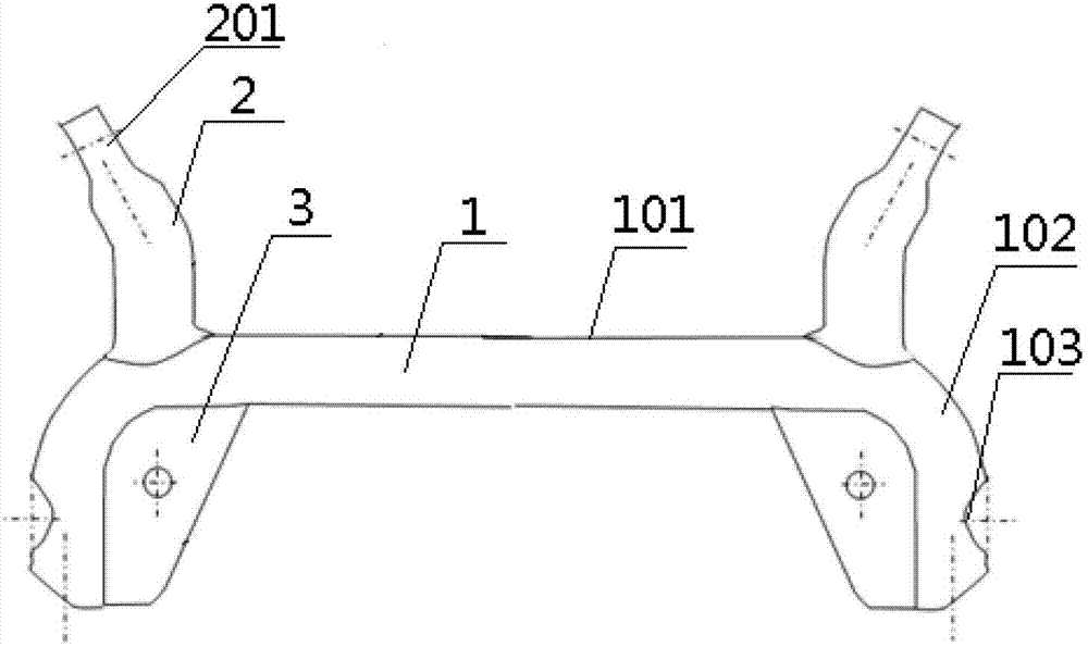
The utility model discloses a novel torsion beam suspension, which comprises a transverse part of the transverse beam, and a U-shaped longitudinal part of the transverse beam formed by bending and extending at both ends thereof in the same direction. A trailing arm, the end of the trailing arm is provided with a bush installation hole. The torsion beam rear suspension structure has strong versatility when design changes occur, such as changes in the suspension posture or optimization of the dynamic performance of the torsion beam, etc., only the cross-sectional shape design of the connecting part of the longitudinal beam and the cross beam needs to be changed, and no longer It is necessary to change the design of parts such as springs and shock absorbers. At the same time, the suspension structure is safe and stable, with high reliability and high fatigue resistance.
Description
技术领域 technical field
本实用新型涉及一种汽车零部件,具体地说是一种车辆的扭转梁式悬架结构。The utility model relates to an auto part, in particular to a torsion beam suspension structure of a vehicle.
背景技术 Background technique
以往,作为车辆的悬架装置,扭转梁式悬架由两侧纵置的纵臂以及连接左右纵臂的横梁予构成。这种扭转梁悬架的抗疲劳性能经常难以保证,后期的设计更改工作需要耗费较多的人力和物力,而且更改设计通常需要更换安装在纵臂上的弹簧和减震器等部件。同时横梁两端与纵臂的连接部位存在着较高的应力,其疲劳强度问题一直难以彻底解决。Conventionally, as a suspension device of a vehicle, a torsion beam type suspension is composed of trailing arms placed vertically on both sides and a cross member connecting the left and right trailing arms. The anti-fatigue performance of this torsion beam suspension is often difficult to guarantee, and later design changes require a lot of manpower and material resources, and design changes usually require replacement of springs and shock absorbers installed on the trailing arms. At the same time, there is a high stress at the joint between the two ends of the beam and the longitudinal arm, and the fatigue strength problem has been difficult to solve completely.
实用新型内容 Utility model content
本实用新型所要解决的技术问题是实现一种结构简单、安全可靠、使用寿命长,具有较好的车辆动力学性能,也便于车辆的平台化开发设计的新型的扭转梁式后悬架。The technical problem to be solved by the utility model is to realize a new type of torsion beam rear suspension with simple structure, safety and reliability, long service life, good vehicle dynamic performance, and convenient vehicle platform development and design.
为了实现上述目的,本实用新型采用的技术方案为:一种新型扭转梁悬架,包括横梁横部,以及在其两端同向弯折延伸构成U形横梁纵部,所述横梁横部端部沿横梁纵部相反方向固定有纵臂,所述的纵臂端部设有衬套安装孔。In order to achieve the above purpose, the technical solution adopted by the utility model is: a new type of torsion beam suspension, including the transverse part of the beam, and its two ends are bent and extended in the same direction to form the longitudinal part of the U-shaped beam, and the ends of the transverse part of the beam are A longitudinal arm is fixed along the opposite direction of the longitudinal part of the beam, and the end of the longitudinal arm is provided with a bush installation hole.
所述的横梁横部与横梁纵部之间焊接有底板,所述的底板布置有弹簧底座和减震器固定销。A base plate is welded between the transverse part of the beam and the longitudinal part of the beam, and the base plate is arranged with a spring base and a fixing pin of a shock absorber.
所述的横梁横部为C形管,当扭转梁悬架固定在车身后,C形管开口方向朝向车辆的后下部。The cross part of the beam is a C-shaped tube, and when the torsion beam suspension is fixed on the vehicle body, the opening direction of the C-shaped tube faces the rear lower part of the vehicle.
所述的横梁纵部端部外侧位置设有轮毂轴支架固定孔。The outer position of the end of the longitudinal part of the beam is provided with a fixing hole for the hub shaft bracket.
两个所述的纵臂固定在横梁横部端部的外张角度为8-15度。The flare angle of the two longitudinal arms fixed on the ends of the transverse part of the beam is 8-15 degrees.
所述的纵臂通过焊接方式连接在横梁上。The longitudinal arm is connected to the beam by welding.
本实用新型的优点在于,该扭转梁式后悬架结构在发生设计变更时通用性强,例如悬架姿态发生变化或扭转梁动力学性能需要优化等,仅更改纵梁与横梁连接部分的截面形状设计即可,不再需更改弹簧和减震器等零部件的设计,同时悬架结构安全稳定,可靠性高,具有较高的抗疲劳强度功能。The utility model has the advantage that the torsion beam type rear suspension structure has strong versatility when design changes occur, for example, the attitude of the suspension changes or the dynamic performance of the torsion beam needs to be optimized. The shape design is sufficient, and there is no need to change the design of parts such as springs and shock absorbers. At the same time, the suspension structure is safe and stable, with high reliability and high fatigue resistance.
附图说明 Description of drawings
下面对本实用新型说明书中每幅附图表达的内容及图中的标记作简要说明:The following is a brief description of the content expressed in each piece of drawings in the specification sheet of the utility model and the marks in the figure:
图1是传统的扭转梁式悬架的俯视图;Fig. 1 is the top view of traditional torsion beam suspension;
图2是本次技术中扭转梁式悬架的俯视图;Fig. 2 is the top view of torsion beam suspension in this technology;
图3是图2的左侧仰视图;Fig. 3 is the bottom view of the left side of Fig. 2;
图4为图3中横梁的沿车辆纵向面的剖视图;Fig. 4 is a sectional view along the vehicle longitudinal plane of the beam in Fig. 3;
图5为本次发明的扭转梁悬架的纵臂与衬套的连接方式;Fig. 5 is the connection mode between the trailing arm and the bushing of the torsion beam suspension of the present invention;
上述图中的标记均为:1、横梁;2、纵臂;3、底板;101、横梁横部;102、横梁纵部;103、轮毂轴支架固定孔;201、衬套安装孔。The marks in the above figures are: 1, beam; 2, longitudinal arm; 3, base plate; 101, transverse part of the beam; 102, vertical part of the beam; 103, fixing hole of hub shaft bracket;
具体实施方式 Detailed ways
参见图1可知,新型扭转梁悬架包括横梁1和纵臂2,其中横梁1由横梁横部101和横梁纵部102组成,横梁纵部102是由横梁横部101两端弯折延伸出的,横梁横部101和横梁纵部102构成U形横梁1,横梁1一体成型,充分保证了横梁1与纵臂2连接部分的强度,提高了扭转梁的使用寿命。如图3所示,横梁1 的横梁横部101的端部有一段光滑曲线过渡的切割加工的曲面,横梁横部101的本体中间部位的剖视图如图4所示为C形管,横梁截面形状可以依据车辆的实际情况进行适当优化。这样既保证横梁1的刚度和扭转强度的同时,又尽量减少材料的用量,从而减少整车质量。当扭转梁悬架固定在车身后,C形管开口方向朝向车辆的后下部,这样既能提高车辆的侧倾中心高度,有效降低车辆的侧倾角度,还具备有效避免其内积存泥土、降低行驶风阻的优点。Referring to Fig. 1, it can be seen that the new torsion beam suspension includes a
横梁横部101端部沿横梁纵部102相反方向固定有纵臂2,纵臂2端部设有衬套安装孔201,如5所示纵臂2前端通过冲压成型出衬套的安装空间,不必像传统的扭转梁需通过一个连接支架来安装橡胶衬套,减少了零件和工艺。纵臂2材料选用圆形钢管采用冲压、窝折方式成型,并通过焊接方式连接在横梁1上,通过前端橡胶衬套支撑在车身上。通过调整纵臂2与横梁1的焊接面设计,即可完成扭转梁式悬架的姿态的变更,这样不会再更改减震器和弹簧等部件,便于车辆的平台化开发设计。A
横梁1两端的纵臂2前端呈外张状,外张角度为8-15度,具体角度可根据车辆的实际状态依据车辆动力学的理论要求和衬套的刚度性能等来适当优化,这种外张设计保证了车辆转弯时的操纵稳定性能,对车辆行驶时的不足转向能起到很好的保障作用。The front ends of the
如图3所示,横梁横部101与横梁纵部102之间焊接有底板3,该底板3布置有弹簧底座和减震器固定销,横梁纵部102端部外侧位置设有轮毂轴支架固定孔103用于安装轮毂轴支架,后轮及相关部件通过该轮毂轴支架1支撑。As shown in Figure 3, a
上面结合附图对本发明进行了示例性描述,显然本实用新型具体实现并不受上述方式的限制,只要采用了本发明的方法构思和技术方案进行的各种非实质性的改进,或未经改进将本发明的构思和技术方案直接应用于其它场合的,均在本实用新型的保护范围之内。The present invention has been exemplarily described above in conjunction with the accompanying drawings. Obviously, the specific implementation of the present invention is not limited by the above-mentioned manner, as long as various insubstantial improvements are carried out by adopting the method concept and technical solutions of the present invention, or without Improvements that directly apply the concept and technical solutions of the present invention to other occasions are within the protection scope of the present utility model.
Claims (6)
Priority Applications (1)
| Application Number | Priority Date | Filing Date | Title |
|---|---|---|---|
| CN 201220255216 CN202703177U (en) | 2012-06-01 | 2012-06-01 | Novel torsion beam suspension |
Applications Claiming Priority (1)
| Application Number | Priority Date | Filing Date | Title |
|---|---|---|---|
| CN 201220255216 CN202703177U (en) | 2012-06-01 | 2012-06-01 | Novel torsion beam suspension |
Publications (1)
| Publication Number | Publication Date |
|---|---|
| CN202703177U true CN202703177U (en) | 2013-01-30 |
Family
ID=47583511
Family Applications (1)
| Application Number | Title | Priority Date | Filing Date |
|---|---|---|---|
| CN 201220255216 Expired - Lifetime CN202703177U (en) | 2012-06-01 | 2012-06-01 | Novel torsion beam suspension |
Country Status (1)
| Country | Link |
|---|---|
| CN (1) | CN202703177U (en) |
Cited By (2)
| Publication number | Priority date | Publication date | Assignee | Title |
|---|---|---|---|---|
| CN103738137A (en) * | 2013-12-19 | 2014-04-23 | 青特集团有限公司 | Novel light through shaft structure |
| CN107719058A (en) * | 2016-08-11 | 2018-02-23 | 上海汽车集团股份有限公司 | Torsion beam, suspension and automobile |
-
2012
- 2012-06-01 CN CN 201220255216 patent/CN202703177U/en not_active Expired - Lifetime
Cited By (2)
| Publication number | Priority date | Publication date | Assignee | Title |
|---|---|---|---|---|
| CN103738137A (en) * | 2013-12-19 | 2014-04-23 | 青特集团有限公司 | Novel light through shaft structure |
| CN107719058A (en) * | 2016-08-11 | 2018-02-23 | 上海汽车集团股份有限公司 | Torsion beam, suspension and automobile |
Similar Documents
| Publication | Publication Date | Title |
|---|---|---|
| CN104210321B (en) | The multi link hind axle of motor vehicles | |
| US7798507B2 (en) | Vehicle suspension apparatus | |
| US20090033141A1 (en) | Powered motor vehicle rear axle of a twist-beam axle type | |
| CN201346970Y (en) | Front independent suspension system for light and medium buses | |
| US7520515B2 (en) | Steer axle suspension | |
| CN203186026U (en) | Novel MPV rear independent suspension system | |
| CN203995534U (en) | The independent front suspension of horizontal non-metal leaf spring | |
| GB2473719A (en) | A structural component for the rear frame structure of a motor vehicle | |
| CN208558933U (en) | A rear torsion beam of an automobile | |
| CN203995530U (en) | A kind of automotive suspension | |
| CN201737054U (en) | Collapsing absorbing energy type auxiliary frame | |
| CN201597405U (en) | Double-rocker independent suspension system | |
| KR101315489B1 (en) | Structure of subframe for vehicle | |
| CN203046804U (en) | Rear suspension system for light automobile | |
| CN104442252A (en) | Front air suspension with X-shaped guiding arm structure for medium bus | |
| CN105774462B (en) | Automobile rear torsion beam structure | |
| CN105365512A (en) | Torsion beam having stabilizer bar | |
| CN106739893B (en) | Beach buggy and rear suspension thereof | |
| CN103241090A (en) | Torsion beam type rear axle | |
| CN103660840A (en) | Torsion beam suspension device | |
| CN202782564U (en) | Torsion beam rear axle | |
| CN207190699U (en) | A kind of torsion beam of automobile formula suspension | |
| CN201442502U (en) | Double rear axle air suspension | |
| CN201849279U (en) | Torsion bar stabilizing device for torsion beam of automobile | |
| CN101456343B (en) | Double wishbone independent suspension without stabilizer bar |
Legal Events
| Date | Code | Title | Description |
|---|---|---|---|
| C14 | Grant of patent or utility model | ||
| GR01 | Patent grant | ||
| CX01 | Expiry of patent term | ||
| CX01 | Expiry of patent term |
Granted publication date: 20130130 |