CN202691649U - Luminaire with light-emitting diode fixing structure - Google Patents
Luminaire with light-emitting diode fixing structure Download PDFInfo
- Publication number
- CN202691649U CN202691649U CN2012202170041U CN201220217004U CN202691649U CN 202691649 U CN202691649 U CN 202691649U CN 2012202170041 U CN2012202170041 U CN 2012202170041U CN 201220217004 U CN201220217004 U CN 201220217004U CN 202691649 U CN202691649 U CN 202691649U
- Authority
- CN
- China
- Prior art keywords
- light
- emitting diode
- circuit board
- emitting diodes
- lamp
- Prior art date
- Legal status (The legal status is an assumption and is not a legal conclusion. Google has not performed a legal analysis and makes no representation as to the accuracy of the status listed.)
- Expired - Fee Related
Links
- 239000000853 adhesive Substances 0.000 claims description 6
- 238000007598 dipping method Methods 0.000 claims 12
- 230000000903 blocking effect Effects 0.000 claims 4
- 230000015572 biosynthetic process Effects 0.000 claims 1
- 238000004519 manufacturing process Methods 0.000 abstract description 6
- 241001465382 Physalis alkekengi Species 0.000 abstract description 2
- 230000000694 effects Effects 0.000 description 16
- 230000001070 adhesive effect Effects 0.000 description 4
- 238000009792 diffusion process Methods 0.000 description 3
- 238000003032 molecular docking Methods 0.000 description 3
- 239000007858 starting material Substances 0.000 description 3
- 238000003780 insertion Methods 0.000 description 2
- 230000037431 insertion Effects 0.000 description 2
- 238000004134 energy conservation Methods 0.000 description 1
- 238000005265 energy consumption Methods 0.000 description 1
- 238000005286 illumination Methods 0.000 description 1
- 210000001503 joint Anatomy 0.000 description 1
- 238000000034 method Methods 0.000 description 1
- 238000006467 substitution reaction Methods 0.000 description 1
- 230000009466 transformation Effects 0.000 description 1
- 238000000844 transformation Methods 0.000 description 1
Images




Landscapes
- Fastening Of Light Sources Or Lamp Holders (AREA)
Abstract
Description
技术领域 technical field
本实用新型有关于一种灯具结构,尤指一种具有发光二极管固定结构的灯具。 The utility model relates to a lamp structure, in particular to a lamp with a light-emitting diode fixing structure.
背景技术 Background technique
由于全球节能减排的提倡,节能照明灯具已成为趋势,故基于低耗能、省电等特点,节能灯如荧光(fluorescent)灯及发光二极管(light emitting diode,发光二极管)应用于照明用途已愈来愈普遍,已逐渐取代传统灯泡如白炽灯而广泛应用各种照明灯具或发光装置中。 Due to the global promotion of energy conservation and emission reduction, energy-saving lighting has become a trend. Therefore, based on the characteristics of low energy consumption and power saving, energy-saving lamps such as fluorescent lamps and light emitting diodes (light emitting diodes) have been used in lighting applications. It is becoming more and more common, and has gradually replaced traditional light bulbs such as incandescent lamps and is widely used in various lighting fixtures or lighting devices.
由于就价格比上总发光流明(lumen)而言,荧光灯仍比发光二极管灯低价,因此目前于民用上,亦占多数。但目前荧光灯的制造方式仍不适合调光,主要是荧光灯的调光亮度无法足够低,且荧光灯调光之后会降低其使用寿命。因此,在有全亮亦有低亮度需求的同一场合中,以荧光灯为主灯以满足全亮需求,或切换至发光二极管为辅灯以满足低亮度需求,将是一理想的方式。 Since fluorescent lamps are still cheaper than light-emitting diode lamps in terms of price compared to total luminous lumens, they are currently in the majority for civilian use. However, the current manufacturing method of fluorescent lamps is still not suitable for dimming, mainly because the dimming brightness of fluorescent lamps cannot be low enough, and the service life of fluorescent lamps will be reduced after dimming. Therefore, in the same occasion where both full-brightness and low-brightness requirements are required, it would be an ideal way to use fluorescent lamps as main lights to meet full-brightness requirements, or switch to LEDs as auxiliary lights to meet low-brightness requirements.
另外,市面上的以LED为主灯,且直接对该LED主灯进行调光,于调至低量度时,有多余功耗的问题。因此,在有全亮亦有低亮度需求的同一场合中,若选用LED为主灯,亦应以该LED主灯满足全亮需求,或切换至另一LED为辅灯以满足低亮度需求,以降低多余功耗。 In addition, LED lights on the market are used as the main light, and the LED main light is directly dimmed. When the light is adjusted to a low level, there is a problem of excess power consumption. Therefore, in the same occasion where both full-brightness and low-brightness requirements are required, if an LED is selected as the main light, the LED main light should also meet the full-brightness requirement, or switch to another LED as the auxiliary light to meet the low-brightness requirement. to reduce excess power consumption.
然而,目前市面上的类似产品,其组件过于繁杂,导致组合好的灯具结构过于复杂,进而有生产不易及组装烦琐的缺点;另外,因发光二极管体积较小,所以置于同平面下,发光二极管的高度会低于荧光灯管,故发光二极管辅灯的出光效果会被荧光灯管的结构所设限,如出光的角度及出光的扩散效果亦受限制,以至于无法满足实际需求。 However, the components of similar products currently on the market are too complicated, which leads to the complex structure of the assembled lamps, which has the disadvantages of difficult production and cumbersome assembly; in addition, because the light-emitting diodes are small in size, they are placed on the same plane to emit light. The height of the diode will be lower than that of the fluorescent tube, so the light output effect of the LED auxiliary lamp will be limited by the structure of the fluorescent tube, such as the angle of light output and the diffusion effect of the light output are also limited, so that it cannot meet the actual needs.
实用新型内容 Utility model content
本实用新型的目的,在于提供一种具有发光二极管固定结构的灯具,其利用使发光二极管固定在电源供应器的壳体上并且灯体围设于发光二极管的外围,进而提高吸顶灯整体的发光效率及照射面的平均;同时,发光二极管固定在壳体上,以使本实用新型灯具的生产成本降低。 The purpose of this utility model is to provide a lamp with a light-emitting diode fixing structure, which uses the light-emitting diode to be fixed on the housing of the power supply and the lamp body to surround the light-emitting diode, thereby improving the overall light emission of the ceiling lamp. The efficiency and the average of the irradiated surface; at the same time, the light-emitting diode is fixed on the shell, so that the production cost of the lamp of the utility model is reduced.
为了达到上述目的,本实用新型提供了一种具有发光二极管固定结构的灯具,包括: In order to achieve the above purpose, the utility model provides a lamp with a light-emitting diode fixing structure, including:
一灯座; a lamp holder;
至少一灯体; at least one lamp body;
一电源供应器,固置在该灯座上,该电源供应器包含一壳体及设置在该壳体内部的一电路板,该灯体和该电路板电性连接; A power supply is fixed on the lamp holder, the power supply includes a housing and a circuit board arranged inside the housing, the lamp body is electrically connected to the circuit board;
至少一发光二极管,固定在该壳体上并和该电路板电性连接,该灯体围设于该发光二极管的外围。 At least one light-emitting diode is fixed on the housing and electrically connected to the circuit board, and the lamp body surrounds the periphery of the light-emitting diode.
进一步地,其还包括一电源模块,该电源模块和该电路板电性连接并置于该壳体内。 Further, it also includes a power module, which is electrically connected with the circuit board and placed in the casing.
进一步地,其中该壳体具有一外盖,该外盖罩盖该电路板,该外盖具有一承放板,该承放板设有至少一开口,该发光二极管具有一出光体及自该出光体延伸的一接脚,该出光体固置在该承放板上,该接脚通过该开口与该电路板电性连接。 Further, the casing has an outer cover, the outer cover covers the circuit board, the outer cover has a receiving plate, and the receiving plate is provided with at least one opening, the light emitting diode has a light emitting body and A pin extending from the light-emitting body, the light-emitting body is fixed on the receiving board, and the pin is electrically connected to the circuit board through the opening.
进一步地,其中该壳体具有一可拔插式外盖,该可拔插式外盖罩盖该电路板,该可拔插式外盖一侧具有一承放板及另一侧具有一对接板,该承放板设有至少一开口,该对接板设有一插脚,该发光二极管具有一出光体及自该出光体延伸的一接脚,该出光体固置在该承放板上,该接脚通过该开口与该插脚电性连接,该插脚插设并电性连接于该电路板。 Further, the housing has a detachable outer cover, the detachable outer cover covers the circuit board, and the detachable outer cover has a receiving plate on one side and a butt joint on the other side. plate, the holding plate is provided with at least one opening, the docking plate is provided with a pin, the light emitting diode has a light emitting body and a pin extending from the light emitting body, the light emitting body is fixed on the receiving plate, the The pin is electrically connected to the pin through the opening, and the pin is inserted and electrically connected to the circuit board.
进一步地,其中该壳体包含一罩盖及固定在该罩盖的一外盖,该罩盖罩盖该电路板,该罩盖设有一贯口,该外盖具有对应该贯口的一承放板,该承放板设有至少一开口,该发光二极管具有一出光体及自该出光体延伸的一接脚,该出光体固置在该承放板上,该接脚通过该开口及该贯口与该电路板电性连接。 Further, the housing includes a cover and an outer cover fixed on the cover, the cover covers the circuit board, the cover is provided with a through opening, and the outer cover has a socket corresponding to the through opening The receiving plate is provided with at least one opening, the LED has a light emitting body and a pin extending from the light emitting body, the light emitting body is fixed on the receiving plate, the pin passes through the opening and The through hole is electrically connected with the circuit board.
进一步地,其中该承放板于该开口周缘形成有一环块,该出光体周围形成有一突出部,该突出部对应该环块定位。 Furthermore, a ring block is formed on the periphery of the opening of the receiving plate, a protruding part is formed around the light emitting body, and the protruding part is positioned corresponding to the ring block.
进一步地,其还包括一黏着剂,该黏着剂被夹置在该突出部及该环块之间。 Further, it also includes an adhesive, and the adhesive is sandwiched between the protruding portion and the ring block.
进一步地,其还包括一固定环,该固定环固定于该承放板上,该固定环设有至少一穿口,该突出部被夹置在该固定环及该环块之间,该出光体通过该穿口裸露于该承放板上部。 Further, it also includes a fixing ring, the fixing ring is fixed on the receiving plate, the fixing ring is provided with at least one opening, the protruding part is sandwiched between the fixing ring and the ring block, the light emitting The body is exposed on the upper part of the receiving board through the opening.
进一步地,其中该承放板于该开口周缘形成有一卡掣部,该出光体周围形成有一突出部,该突出部与卡掣部相互卡合。 Furthermore, a locking portion is formed on the periphery of the opening of the receiving plate, a protruding portion is formed around the light emitting body, and the protruding portion and the locking portion are engaged with each other.
进一步地,其中该卡掣部为朝该壳体内部方向延伸的复数扣臂。 Furthermore, the engaging portion is a plurality of clasp arms extending toward the inside of the housing.
进一步地,其中该卡掣部为朝该壳体外部方向延伸的复数扣臂。 Furthermore, the locking portion is a plurality of clasp arms extending toward the outside of the housing.
进一步地,其还包括一固定柱,该承放板朝该壳体内部方向延伸有一中空管,并相对该中空管形成有该开口,该固定柱穿置定位于该中空管中,该固定柱设有至少一插孔,该接脚对应该插孔插设。 Further, it also includes a fixing column, the receiving plate extends a hollow tube towards the inside of the housing, and the opening is formed relative to the hollow tube, the fixing column is inserted and positioned in the hollow tube, The fixing post is provided with at least one insertion hole, and the pin is inserted into the insertion hole.
进一步地,其还包括一导光透镜,该导光透镜装设在该外盖上并罩盖该发光二极管。 Further, it also includes a light guide lens, the light guide lens is arranged on the outer cover and covers the light emitting diode.
进一步地,其中该灯体固定在该灯座上或该电源供应器上。 Further, the lamp body is fixed on the lamp socket or the power supply.
进一步地,其还包括一切换单元,该切换单元和该电路板电性连接并用以切换该灯体及该发光二极管的开启或关闭。 Further, it also includes a switch unit, which is electrically connected to the circuit board and used to switch the light body and the light emitting diode on or off.
进一步地,其中该灯体为气体放电灯。 Further, the lamp body is a gas discharge lamp.
进一步地,其中该灯体为发光二极管。 Further, the lamp body is a light emitting diode.
本实用新型还有以下功效: The utility model also has the following effects:
发光二极管固定在电源供应器的壳体上并且灯体围设于发光二极管的外围,可避免发光二极管辅灯的出光效果受灯体主灯的影响而降低,即可避免灯体及发光二极管互相限制对方的出光效果,进而提高了灯具整体的发光效率及照射面的平均。 The light-emitting diode is fixed on the housing of the power supply and the lamp body is surrounded by the periphery of the light-emitting diode, which can prevent the light output effect of the auxiliary light of the light-emitting diode from being affected by the main light of the light body, and can avoid mutual interference between the light body and the light-emitting diode. Limit the light output effect of the other side, thereby improving the overall luminous efficiency of the lamp and the average of the illuminated surface.
另外,发光二极管固定在壳体上,使本实用新型具有发光二极管固定结构的灯具降低了生产成本。 In addition, the light-emitting diodes are fixed on the housing, which reduces the production cost of the lamp with the light-emitting diode fixing structure of the utility model.
又,本实用新型灯具还包括切换单元,用以切换灯体及发光二极管的开启或关闭,以使在有全亮亦有低亮度需求的同一场合中,使用者可自行选择性地切换发光二极管及灯体,达到以灯体为主灯以满足全亮需求,或切换至发光二极管为辅灯以满足低亮度需求。 Moreover, the lamp of the present utility model also includes a switching unit, which is used to switch the lamp body and the light-emitting diodes on or off, so that the user can selectively switch the light-emitting diodes in the same occasion where there is a demand for full brightness and low brightness. And the lamp body, so as to use the lamp body as the main lamp to meet the full brightness requirement, or switch to the LED as the auxiliary lamp to meet the low brightness requirement.
再者,本实用新型灯具还包括导光透镜,以增加发光二极管的面积,进而提高了发光二极管的出光效果;此外,导光透镜呈凸透镜外,也为凹透镜或平透镜,使本实用新型灯具可方便地选择所需要的发光二极管出光的角度及出光的扩散效果,以实际满足多项应用需求。 Furthermore, the lamp of the present invention also includes a light guide lens to increase the area of the light-emitting diode, thereby improving the light output effect of the light-emitting diode; in addition, the light guide lens is not only a convex lens, but also a concave lens or a flat lens, so that the lamp of the present utility model It is convenient to select the required light emitting angle of the light emitting diode and the diffusion effect of the light, so as to actually meet multiple application requirements.
附图说明 Description of drawings
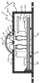
图1, 是本实用新型具有发光二极管固定结构的灯具第一实施例的立体分解图; Fig. 1 is the three-dimensional exploded view of the first embodiment of the lamp with light-emitting diode fixing structure of the present invention;
图2, 是本实用新型第一实施例的剖面示意图; Fig. 2 is a schematic sectional view of the first embodiment of the utility model;
图 3,是本实用新型第二实施例的剖面示意图; Fig. 3 is a schematic cross-sectional view of the second embodiment of the utility model;
图4 ,是本实用新型第三实施例的剖面示意图; Fig. 4 is a schematic cross-sectional view of the third embodiment of the utility model;
图5 ,是本实用新型第四实施例的剖面示意图; Fig. 5 is a schematic cross-sectional view of the fourth embodiment of the utility model;
图6 ,是本实用新型第五实施例的剖面示意图; Fig. 6 is a schematic cross-sectional view of the fifth embodiment of the utility model;
图7 ,是本实用新型第六实施例的组合示意图; Fig. 7 is the combined schematic view of the sixth embodiment of the present utility model;
图 8,是本实用新型第七实施例的组合示意图; Fig. 8 is a combined schematic view of the seventh embodiment of the present utility model;
图 9,是本实用新型第七实施例的剖面示意图; Fig. 9 is a schematic cross-sectional view of the seventh embodiment of the present utility model;
图 10,是本实用新型第八实施例的剖面示意图。 Fig. 10 is a schematic cross-sectional view of the eighth embodiment of the present invention.
图中,1…灯座, 2…灯体; In the figure, 1...lamp holder, 2...lamp body;
3…电源供应器, 31…壳体; 3...power supply unit, 31...housing;
310…底板, 311…外盖; 310…bottom plate, 311…outer cover;
311’ …可拔插式外盖, 3111…承放板; 311’ …removable plug-in cover, 3111…receiving plate;
3112…围板, 3113…对接板; 3112…coaming plate, 3113…butt plate;
3114…插脚, 312…开口; 3114…pin, 312…opening;
313…环块 , 314…卡掣部; 313...Ring block, 314...Catch part;
3141…扣臂 , 315…中空管; 3141…Clasp arm, 315…Hollow tube;
316…罩盖 , 3161…贯口; 316...cover, 3161...through mouth;
32…电路板 , 321…电源模块; 32...circuit board, 321...power module;
322…启动器, 323…切换单元; 322…starter, 323…switching unit;
4…发光二极管, 41…出光体; 4...light-emitting diode, 41...light-emitting body;
411…突出部 , 42…接脚; 411...protruding part, 42...pin;
5…导光透镜 , 6…黏着剂; 5...light guide lens, 6...adhesive;
7…固定环 , 71…穿口; 7...Fixing ring, 71...Through the mouth;
8…固定柱 , 81…插孔。 8...fixed column, 81...jack.
具体实施方式 Detailed ways
下面结合附图和具体实施例对本实用新型作进一步说明,以使本领域的技术人员可以更好的理解本实用新型并能予以实施,但所举实施例不作为对本实用新型的限定。 The utility model will be further described below in conjunction with the accompanying drawings and specific embodiments, so that those skilled in the art can better understand the utility model and implement it, but the examples given are not intended to limit the utility model.
如图1和图2所示,本实用新型提供一种具发光二极管固定结构的灯具,此灯具主要包括一灯座1、至少一灯体2、一电源供应器3及至少一发光二极管4。
As shown in FIG. 1 and FIG. 2 , the utility model provides a lamp with a light-emitting diode fixing structure. The lamp mainly includes a
灯体2固定在灯座1上;其中,灯体2可为气体放电灯(Gas-discharge lamps)或发光二极管,又气体放电灯的最佳实施例为荧光灯(Fluorescent),灯体2的数量可为一或复数,灯体2为一环形体并围设于电源供应器3及发光二极管4的外围,但灯体2的外形不以此为限,其可为任何几何形状。
The
电源供应器3固置在灯座1上,电源供应器3包含一壳体31及设置在壳体31内部的一电路板32,灯体2和电路板32电性连接,此电路板32装设有一电源模块321(用以提供灯体2及发光二极管4所需的电源)及气体放电灯启动所需的一启动器322(也可为电子启动装置),若灯体2为发光二极管可不需要此启动器322;其中,壳体31具有相互组合的一底板310及一外盖311,电路板32固置在底板310上,外盖311罩盖电路板32,外盖311具有一承放板3111及自承放板3111延伸有一围板3112,承放板3111设有至少一开口312并自开口312周缘延伸有一环块313。
The
发光二极管4的最佳实施例为一插脚式发光二极管,但不以此为限制,发光二极管4固定在壳体31上并和电路板32电性连接;此发光二极管4固定在承放板3111上,接脚42通过开口312与电路板32电性连接,详细说明如下,发光二极管4具有一出光体41及自出光体41延伸的一接脚42,出光体41周围形成有一突出部411,突出部411对应环块313定位。
The best embodiment of the
本实用新型灯具还包括一切换单元323,切换单元323和电路板32电性连接并用以切换灯体2及发光二极管4的开启或关闭。
The lamp of the present invention also includes a
本实用新型灯具还包括一导光透镜5,导光透镜5装设在外盖311上并罩盖发光二极管4;其中,导光透镜5可为凸透镜、凹透镜或平透镜的样态,但其不以此为限。
The utility model lamp also includes a
本实用新型灯具还包括一黏着剂6,黏着剂6被夹置在突出部411及环块313之间,以使发光二极管4固定在环块313上。
The lamp of the present invention also includes an adhesive 6 , which is sandwiched between the protruding
本实用新型具有发光二极管固定结构的灯具组合,其利用电源供应器3固置在灯座1上,电源供应器3包含壳体31及设置在壳体31内部的电路板32,灯体2和电路板32电性连接;发光二极管4固定在壳体31上并和电路板32电性连接,灯体2围设于该发光二极管4的外围。借此,可避免发光二极管4辅灯的出光效果受灯体2主灯的影响而降低,即可避免灯体2及发光二极管4互相限制对方的出光效果,进而提高灯具整体的发光效率及照射面的平均。
The utility model has a lamp assembly with a light-emitting diode fixed structure, which is fixed on the
另外,发光二极管4固定在壳体31上,使本实用新型具有发光二极管固定结构的灯具的生产成本降低。
In addition, the
又,本实用新型灯具还包括切换单元323,切换单元323和该电路板32电性连接并用以切换灯体2及发光二极管4的开启或关闭,以使在有全亮亦有低亮度需求的同一场合中,使用者可自行选择性地切换发光二极管4及灯体2,达到以灯体2为主灯以满足全亮需求,或切换至发光二极管4为辅灯以满足低亮度需求。
In addition, the lamp of the present utility model also includes a
再者,本实用新型灯具还包括导光透镜5,以增加发光二极管4的面积,进而提高发光二极管4的出光效果;此外,导光透镜5呈凸透镜外,也可为凹透镜或平透镜,使本实用新型灯具可方便地选择所需要的发光二极管4出光的角度及出光的扩散效果,以实际满足多项应用需求。
Moreover, the
如图3和图4所示,是本实用新型灯具第二实施例及第三实施例,其为发光二极管4固定在承放板3111上的另一结构,外盖311于开口312周缘形成有一卡掣部314,卡掣部314可为朝壳体31内部或外部方向延伸的复数扣臂3141;又,出光体41周围形成有一突出部411,突出部411与卡掣部314相互卡合,以达成相同于上述的功能与效果。
As shown in Figure 3 and Figure 4, it is the second embodiment and the third embodiment of the utility model lamp, which is another structure in which the
如图5所示,是本实用新型灯具第四实施例,其为发光二极管4固定在承放板3111上的又一结构,本实用新型灯具还包括一固定环7,固定环7固定于承放板3111上,固定环7设有至少一穿口71,突出部411被夹置在固定环7及环块313之间,出光体41通过穿口71裸露于承放板3111上部,以达成相同于上述的功能与效果。另外,导光透镜5非本实用新型灯具的必要组件,故其可视实际情况予以删除。
As shown in Figure 5, it is the fourth embodiment of the utility model lamp, which is another structure in which the
如图6所示,是本实用新型灯具第五实施例,其为发光二极管4固定在承放板3111上的再一结构,本实用新型灯具还包括一固定柱8,承放板3111朝壳体31内部方向延伸有一中空管315,并相对中空管315形成有开口312,固定柱8穿置定位于中空管315中,固定柱8设有至少一插孔81,接脚42对应插孔81插设,以达成相同于上述的功能与效果。
As shown in Figure 6, it is the fifth embodiment of the utility model lamp, which is another structure in which the light-emitting
如图7、图8和图9所示,是本实用新型灯具第六和第七实施例,其为电源供应器3的另一实施例,此壳体31包含底板310、外盖311及可拔插式外盖311’,电路板32固置在底板310上,此外盖311及可拔插式外盖311’共同罩盖电路板32,且灯体2固定于可拔插式外盖311’上并围设于发光二极管4的外围。
As shown in Fig. 7, Fig. 8 and Fig. 9, it is the sixth and seventh embodiments of the lamps and lanterns of the present invention, which is another embodiment of the
其中,发光二极管4可固定在外盖311上或可拔插式外盖311’上,发光二极管4固定于外盖311上时,如图2至图5所示;发光二极管4固定于可拔插式外盖311’上时,其详细说明如下,可拔插式外盖311’一侧具有一承放板3111及另一侧具有一对接板3113,承放板3111设有至少一开口312,对接板3113设有一插脚3114,出光体41固置在承放板3111上,接脚42通过开口312与插脚3114电性连接,插脚3114插设并电性连接于电路板32;另外,本实施例发光二极管4固定在承放板3111的方式,相同图2至图5所示发光二极管4固定在壳体31上的结构,以达成相同于上述的功能与效果。
Wherein, the
如图10所示,是本实用新型灯具第八实施例,其为电源供应器3的又一实施例,其中壳体31包含底板310、罩盖316及固定在罩盖316上的一外盖311,电路板32固置在底板310上,罩盖316罩盖电路板32,罩盖316设有一贯口3161,外盖311具有对应贯口3161的一承放板3111,承放板3111设有至少一开口312,发光二极管4具有出光体41及自出光体41延伸的接脚42,出光体41固置在承放板3111上,接脚42通过开口312及贯口3161与电路板32电性连接;另外,本实施例发光二极管4固定在承放板3111上的方式,相同图2至图5所示发光二极管4固定在壳体31上的结构,以达成相同于上述的功能与效果。
As shown in Figure 10, it is the eighth embodiment of the utility model lamp, which is another embodiment of the
以上所述实施例仅是为充分说明本实用新型而所举的较佳的实施例,本实用新型的保护范围不限于此。本技术领域的技术人员在本实用新型基础上所作的等同替代或变换,均在本实用新型的保护范围之内。本实用新型的保护范围以权利要求书为准。 The above-mentioned embodiments are only preferred embodiments for fully illustrating the utility model, and the protection scope of the utility model is not limited thereto. Equivalent substitutions or transformations made by those skilled in the art on the basis of the present utility model are all within the protection scope of the present utility model. The scope of protection of the utility model shall be determined by the claims.
Claims (17)
Priority Applications (1)
| Application Number | Priority Date | Filing Date | Title |
|---|---|---|---|
| CN2012202170041U CN202691649U (en) | 2012-05-15 | 2012-05-15 | Luminaire with light-emitting diode fixing structure |
Applications Claiming Priority (1)
| Application Number | Priority Date | Filing Date | Title |
|---|---|---|---|
| CN2012202170041U CN202691649U (en) | 2012-05-15 | 2012-05-15 | Luminaire with light-emitting diode fixing structure |
Publications (1)
| Publication Number | Publication Date |
|---|---|
| CN202691649U true CN202691649U (en) | 2013-01-23 |
Family
ID=47547267
Family Applications (1)
| Application Number | Title | Priority Date | Filing Date |
|---|---|---|---|
| CN2012202170041U Expired - Fee Related CN202691649U (en) | 2012-05-15 | 2012-05-15 | Luminaire with light-emitting diode fixing structure |
Country Status (1)
| Country | Link |
|---|---|
| CN (1) | CN202691649U (en) |
-
2012
- 2012-05-15 CN CN2012202170041U patent/CN202691649U/en not_active Expired - Fee Related
Similar Documents
| Publication | Publication Date | Title |
|---|---|---|
| JP5357173B2 (en) | LED lamp for bulb type AC power supply | |
| US8911108B2 (en) | Light bulb shaped lamp and lighting apparatus | |
| JP5545547B2 (en) | Light source body and lighting apparatus | |
| JP2012248687A (en) | Light-emitting module and illumination apparatus | |
| JP4971530B2 (en) | lamp | |
| TWM314823U (en) | Light emitting diode light tube | |
| JP2009117346A (en) | Lighting device | |
| KR101049162B1 (en) | Straight LED Lamp Assembly | |
| JP5662065B2 (en) | Straight tube lamp and lighting device | |
| CN204403966U (en) | Lighting fixtures and auxiliary light source units | |
| KR20100069095A (en) | Luminescent diode lighting apparatus | |
| TWM449908U (en) | Structure for LED (light emitting diode) lamp | |
| CN202327907U (en) | Light emitting diode (LED) street lamp light source capable of realizing direct sodium lamp replacement | |
| CN202691833U (en) | Ceiling light structure with dual light emitting modes | |
| TW201333370A (en) | Lamp and lighting device using the same | |
| CN202884577U (en) | Light-emitting diode (LED) candle lamp | |
| CN201277453Y (en) | Lamp holder module of lamp | |
| CN110242867A (en) | A kind of module type LED light source | |
| JP3116268U (en) | Lamp unit | |
| CN202791692U (en) | Dual-beam mode ceiling light with transparent cover | |
| CN202691834U (en) | Luminaire with light-emitting diode module fixing structure | |
| CN200968549Y (en) | Light-emitting diode lampshade engaging structure | |
| TWM601313U (en) | Modular building block type light bulb device | |
| JP5617982B2 (en) | Lamp with lamp and lighting equipment | |
| CN108870118A (en) | A kind of combined LED lamp tube |
Legal Events
| Date | Code | Title | Description |
|---|---|---|---|
| C14 | Grant of patent or utility model | ||
| GR01 | Patent grant | ||
| CF01 | Termination of patent right due to non-payment of annual fee |
Granted publication date: 20130123 Termination date: 20160515 |
|
| CF01 | Termination of patent right due to non-payment of annual fee |