CN202689175U - Water collecting well desilting system - Google Patents
Water collecting well desilting system Download PDFInfo
- Publication number
- CN202689175U CN202689175U CN 201220175728 CN201220175728U CN202689175U CN 202689175 U CN202689175 U CN 202689175U CN 201220175728 CN201220175728 CN 201220175728 CN 201220175728 U CN201220175728 U CN 201220175728U CN 202689175 U CN202689175 U CN 202689175U
- Authority
- CN
- China
- Prior art keywords
- collecting well
- water collecting
- water
- desilting
- silt
- Prior art date
- Legal status (The legal status is an assumption and is not a legal conclusion. Google has not performed a legal analysis and makes no representation as to the accuracy of the status listed.)
- Expired - Fee Related
Links
Images

Landscapes
- Sewage (AREA)
Abstract
The utility model relates to a water collecting well desilting system, and aims at providing the water collecting well desilting system with the advantages that the operation is convenient, the energy consumption is low, the efficiency is high, a water discharge system of an electric station is not used, and the water discharge pipeline abrasion is avoided. The water collecting well desilting system has the technical scheme that a water discharge facility is arranged in a water collecting well of the water collecting well desilting system, and a sand-containing water flow gathering pipe is buried and arranged in a lower region of the water collecting well near the bottom. The water collecting well desilting system is characterized in that a bottom plate of the water collecting well has a certain inclination angle, a bucket type desilting device is arranged in a position above the water collecting well corresponding to the lowest position of the bottom plate, and the bottom of the water collecting well is provided with a sand density and sand depositing height measuring system and a sand gathering high-pressure flushing system. The water collecting well desilting system is applicable to the deposit cleaning in hydropower station underground factory buildings and dam bodies and at the bottom of the water collecting well, is applicable to the deposit cleaning at the bottom of the water collecting well in a water pumping pump station, and is also applicable to regions of water taking pools of various water diversion projects, deposition pools of sewage treatment plants and the like.
Description
Technical field
The utility model relates to a kind of collecting well desilting system.Be applicable to water power and hydraulic engineering, be particularly useful for the cleaning of the collecting well bottom deposit in underground workshop, dam body and the cushion pool, and the cleaning of the collecting well of water pump station bottom deposit, equally also be applicable to the water intaking pond of each diversion works and the zones such as sedimentation basin of Wastewater Treatment Plant.
Background technology
Power station and pumping plant generally all are provided with the collecting well of discharging factory building and unit percolating water, and some also is provided with the collecting well of unit maintenance draining.Curtain grouting around the construction period factory building may cause a large amount of mud infiltrations to enter collecting well; The power station is after putting into operation simultaneously, because the aggravation of upstream, river course silt loss, silt passes through the percolating water Artesian Drainage of unit runner to collecting well.Silt in the collecting well accumulates over a long period, and the water pump that affects in the collecting well is normally moved, and contains simultaneously the mortar current and causes drainage pump wearing and tearing aggravation, so that can't normally move.
When collecting well alluvial problem occurring, the mode that power plant or pumping plant often adopt is the labor cleaning, and namely the desilting personnel directly go into the well and dig clearly, and manually-operated is time-consuming, and efficient is not high, and at downhole operations, affects the personnel health.
In recent years, some power plant and pumping plant by water under high pressure and compressed air purge system are set, and in conjunction with seepage and the water drainage system for maintenance in power station, are provided with collecting well sewage evacuation system in collecting well.Namely by being arranged in collecting well on every side and high-pressure water pipe and the compressed air hose of bottom, quote water under high pressure and compressed air rinsing and purging collecting well bottom, make together shuttling movement of mud, sand and the water body of alluvial bottom collecting well, be mixed into one, discharge separately outside the factory by the effluent discharge equipment in the collecting well again or use power station drainage system pipeline, discharge outside the factory.The exhaust apparatus of foul water system mainly contains proof submersible sand discharging pump or jet pump forms.This kind desilting mode can solve the problem of collecting well Sediment Siltation basically, but owing to will drop into high-pressure water and compressed air, and the foul water system that drops into, pump head is often all higher, need to expend the more energy.When the collecting well desilting, normal drainage system can not move simultaneously, carries a large amount of silt in the sewage of stiring and make muddy and can produce wearing and tearing to drainage pump and discharge pipe line.
Present hydroelectric station design is considered from safer angle, the position of its drainpipe outlet all is in higher position, especially for scale larger power station or pumping plant, the volume of its collecting well and the degree of depth are all larger, select relatively difficulty of larger capacity, high-lift foul water pump, even in some cases, select less than suitable submersible sewage pump.And the collecting well in power station some regional collecting well of the inside such as dam and the cushion pool, since all distant apart from pressure water source and compressed air gas source, relatively difficulty is set separately then, and the draining lift is also higher, selects again the dredge pump less than suitable types.
Summary of the invention
The technical problems to be solved in the utility model is: for the problem of above-mentioned existence, provide a kind of easy to operate, time saving and energy saving, less energy intensive and the high collecting well desilting system of efficient, not by the drainage system in power station, avoid the wearing and tearing of discharge pipe line.
The technical scheme that the utility model adopts is: a kind of collecting well desilting system, installing drainage in the collecting well, this collecting well is buried underground near the lower region, bottom and is contained sand current manifold trunk, it is characterized in that: the collecting well base plate arranges certain gradient, and collecting well top, corresponding base plate lowest part are installed the grab type Accrete clearing device; The collecting well bottom arranges silt density and Sediment Siltation altitude measurement system and silt and compiles high-pressure washing system.
Described grab type Accrete clearing device comprises the lifting appliance of frame on the collecting well side walls, installs the grab bucket that is used for digging clearly deposit in the collecting well at the lifting rope of lifting appliance.
Described grab bucket sidepiece is offered some drain holes, and the pore gauze wire cloth is set in the drain hole.
Described lifting appliance is bridge machine or electric block.
Described silt density and Sediment Siltation altitude measurement system have load cell, ball float and fixed support, and fixed support is arranged on the different elevations in collecting well bottom, hangs load cell on the fixed support, hangs ball float on this load cell; Load cell connects through transmission cable surveys mud density secondary meter, the monitoring system in this Instrument connection control room.
Described silt compiles high-pressure washing system and has spout towards the jet nozzle of base plate, and this jet nozzle connects the outer high service system of collecting well through the high pressure washing pipe for subsequent use with separation valve door.
The beneficial effects of the utility model are: with in the past collecting well desilting mode comparatively speaking, this kind desilting processing mode can realize the silt degree of depth in the collecting well is monitored and reported to the police; Needed equipment and input are all less; The desilting equipment operation is succinct convenient, but the not timing operation is consumed energy also less; The silt cleaning can be avoided the wearing and tearing of discharge pipe line not by means of the drainage system in power station; Desilting mode is applied widely, when desilting work launches, also can not have influence on the normal use of drainage system; Can the silt of deposition be transported specially and process, avoid downstream river course is produced secondary pollution.
Description of drawings
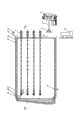
Fig. 1 is structural representation of the present utility model.
Fig. 2 is the A-A sectional view of Fig. 1.
The specific embodiment
As shown in Figure 1 and Figure 2, the present embodiment is a kind of novel collecting well desilting system, collecting well 6 interior installing drainages 7 in this system, it (is that the collecting well base plate has a zone lower that the collecting well base plate is made suitable angle of inclination, all the other baseplate zones are regional angled inclination therewith, be convenient to the deposit in the collecting well is concentrated on this zone), this collecting well is buried silt carrying flow manifold trunk 9 underground near the lower region, bottom.Above collecting well, corresponding base plate lowest part installs the grab type Accrete clearing device.In the collecting well bottom silt density and Sediment Siltation altitude measurement system and silt are set also in the present embodiment and compile high-pressure washing system.
The grab type Accrete clearing device comprises the lifting appliance 1 that is erected on the collecting well 6 top side walls in this example, installs the grab bucket 3 that is used for digging clearly deposit in the collecting well at the lifting rope 2 of lifting appliance.Lifting appliance 1 can be used the bridge machine of drainage for overhaul equipment in the present embodiment, also can adopt the grab type special purpose crane in conjunction with the pattern of grab bucket.According in situ overhaul operation and the needed bridge machine of desilting function, also can design a kind of novel bridge crane, the combination that is equivalent to hook type bridge machine and grab type bridge machine: namely this bridge machine is comprised of cart walking mechanism and two carriage walkings and lifting mechanism, one of them dolly only is comprised of a lifting electric motor, be linked with suspension hook on the lifting rope, can finish the maintenance of pump house internal drainage equipment; The another one dolly opens and closes motor by lifting electric motor and grab bucket and forms, and can finish hoisting and opening and closing of grab bucket, finishes the desilting task in the collecting well.Grab bucket 3 described in this example can adopt wireless remotecontrol hydraulic pressure with grab bucket and electrodynamic type grab bucket, can also in conjunction with the characteristics of grab type bridge crane, adopt four rope grab.In conjunction with the characteristics of working environment, the sidepiece of grab bucket need to be offered the drain hole of some, also need to gauze wire cloth be set in drain hole simultaneously, is convenient to tackle a large amount of silt and flows out with current.The volume of grab bucket is unsuitable excessive, and the lifting volume should be controlled at 0.5m
3In, lifting deposit weight also should be controlled in the 0.5t, is convenient to enter hole or the little thing hole of hanging by the floor setting of collecting well top.
The silt density that adopts in the present embodiment and Sediment Siltation altitude measurement system have load cell 17, ball float 18 and fixed support 16, fixed support 16 is arranged on the different elevations in collecting well 6 bottoms, hang load cell 17 on the fixed support, hang ball float 18 on this load cell; Load cell 17 connects through transmission cable 15 surveys mud density secondary meter 14, the monitoring system 13 in this Instrument connection control room.
Silt density utilizes the buoyancy of different water bodys and the different generations of silt different medium density different with the Sediment Siltation altitude measurement system, measures the density of shoal materials.The density of on-line monitoring collecting well bottom dielectric by ball float 18 and the load cell 17 that different elevations are set, can be understood the height of collecting well shaft bottom Sediment Siltation in real time.When the density that monitors deposit during to a certain extent greater than the density of water body, silt density and Sediment Siltation altitude measurement system can be reported to the police, and the notice maintainer of power plant clears up collecting well bottom shoal materials.
Silt compiles high-pressure washing system and has jet nozzle 12 in this collecting well desilting system, and the spout of this jet nozzle is towards the floor, and through the high service system that high pressure washing pipe 10 for subsequent use connects outside the collecting wells 6, this high pressure washing pipe for subsequent use is provided with separation valve door 11.High pressure washing pipe 10 for subsequent use can be at collecting well 6 bottom silts when automatic sliding drops down onto the bottommost of collecting well fully, to around mud wash, make it migrate to the collecting well lowest part.
The dredging method of the present embodiment is as follows:
A, at first contain that percolating water and unit percolating water are pooled in the collecting well 6 by silt carrying flow manifold trunk 9 in the husky underground power house, because water amount of seepage is little, the collecting well current are relatively steady simultaneously, and silt can constantly be deposited on collecting well 6 lowers;
B, basis are arranged on the stressing conditions of collecting well 6 bottom ball floats 18, judge the density of mud silt, indirectly judge the height of Sediment Siltation.When mud and sandstone deposited to certain altitude, when namely the density of bottom mud was greater than the numerical value set in advance, monitoring system 13 was reported to the police, and the notice maintainer of power plant clears up collecting well;
C, by starting lifting appliance 1 and grabbing bucket 3, dig clearly collecting well 6 interior silts, and shipment special deposit collecting box that arranges in the tipping lorry 8 or in the pump house to the ground, through deposition after a while, after discharging the percolating water in the deposit, be transported to by special personnel or vehicle and focus on outside the factory and stack;
D, grabbed bucket after cleaning finishes at the silt of bottommost, can be enabled the high pressure washing pipe 10 for subsequent use that is arranged on collecting well 6 bottoms, the silt around the base plate is rushed bottommost to collecting well, be convenient to utilize the thoroughly silts of cleaning collecting wells bottom of grab bucket 3;
E, after cleaning is finished, after treating that current recover to stablize, measure the density of bottom shoal materials by silt density and Sediment Siltation altitude measurement system, measure the size of numerical value according to it, whether the silt of judging collecting well 6 bottoms is cleaned, then return step c such as silt density backlog demand, until silt density meets the demands.
The tipping lorry 8 that adopts in the method is preferably small-size dump truck, is convenient to be in the drainage pump chamber.Tilter should leave drain hole, and is provided with isolating valve.Ponding in silt and mud is closed isolating valve after discharging and finishing, and just allows tipping lorry that silt is transported outside the factory, avoids in transportation, pollutes the communications and transportation passage.
Claims (6)
1. collecting well desilting system, installing drainage (7) in the collecting well (6), this collecting well is buried underground near bottom section and is contained sand current manifold trunk (9), it is characterized in that: the collecting well base plate arranges certain gradient, and collecting well top, corresponding base plate lowest part are installed the grab type Accrete clearing device; The collecting well bottom arranges silt density and Sediment Siltation altitude measurement system and silt and compiles high-pressure washing system.
2. collecting well desilting system according to claim 1, it is characterized in that: described grab type Accrete clearing device comprises the lifting appliance (1) of frame on collecting well (6) side walls, installs the grab bucket (3) that is used for digging clearly deposit in the collecting well at the lifting rope (2) of lifting appliance.
3. collecting well desilting system according to claim 2, it is characterized in that: described grab bucket (3) sidepiece is offered some drain holes, and the pore gauze wire cloth is set in the drain hole.
4. collecting well desilting system according to claim 2, it is characterized in that: described lifting appliance (1) is bridge machine or electric block.
5. collecting well desilting system according to claim 2, it is characterized in that: described silt density and Sediment Siltation altitude measurement system have load cell (17), ball float (18) and fixed support (16), fixed support (16) is arranged on the different elevations in collecting well (6) bottom, hang load cell (17) on the fixed support, hang ball float (18) on this load cell; Load cell (17) connects through transmission cable (15) surveys mud density secondary meter (14), the monitoring system (13) in this Instrument connection control room.
6. collecting well desilting system according to claim 5, it is characterized in that: described silt compiles high-pressure washing system and has spout towards the jet nozzle (12) of base plate, and this jet nozzle connects the outer high service system of collecting well (6) through the high pressure washing pipe for subsequent use (10) with separation valve door (11).
Priority Applications (1)
| Application Number | Priority Date | Filing Date | Title |
|---|---|---|---|
| CN 201220175728 CN202689175U (en) | 2012-04-24 | 2012-04-24 | Water collecting well desilting system |
Applications Claiming Priority (1)
| Application Number | Priority Date | Filing Date | Title |
|---|---|---|---|
| CN 201220175728 CN202689175U (en) | 2012-04-24 | 2012-04-24 | Water collecting well desilting system |
Publications (1)
| Publication Number | Publication Date |
|---|---|
| CN202689175U true CN202689175U (en) | 2013-01-23 |
Family
ID=47544813
Family Applications (1)
| Application Number | Title | Priority Date | Filing Date |
|---|---|---|---|
| CN 201220175728 Expired - Fee Related CN202689175U (en) | 2012-04-24 | 2012-04-24 | Water collecting well desilting system |
Country Status (1)
| Country | Link |
|---|---|
| CN (1) | CN202689175U (en) |
Cited By (7)
| Publication number | Priority date | Publication date | Assignee | Title |
|---|---|---|---|---|
| CN102635133A (en) * | 2012-04-24 | 2012-08-15 | 中国水电顾问集团华东勘测设计研究院 | Sump dredging system and mode |
| CN107165260A (en) * | 2017-06-05 | 2017-09-15 | 天津海泰市政绿化有限公司 | A kind of mud clean method of rainfall pumping station |
| CN107626700A (en) * | 2017-09-30 | 2018-01-26 | 武汉圣禹排水系统有限公司 | Rainwater treatment pond flusher and the online device for treating rain water for including it |
| CN109163656A (en) * | 2018-09-29 | 2019-01-08 | 中国科学院亚热带农业生态研究所 | A kind of device and method of determining karst pipeline sediment siltation depth |
| CN109958603A (en) * | 2019-02-19 | 2019-07-02 | 安徽富通环保节能科技股份有限公司 | A kind of bilge well vacuum pump holder and its installation method |
| CN110924514A (en) * | 2019-12-06 | 2020-03-27 | 山东良成环保科技股份有限公司 | Automatic dirt removing and hardening preventing system for bottom of rainwater pumping station |
| CN113309046A (en) * | 2021-06-02 | 2021-08-27 | 杨犇 | A manger plate dykes and dams for hydraulic and hydroelectric engineering |
-
2012
- 2012-04-24 CN CN 201220175728 patent/CN202689175U/en not_active Expired - Fee Related
Cited By (8)
| Publication number | Priority date | Publication date | Assignee | Title |
|---|---|---|---|---|
| CN102635133A (en) * | 2012-04-24 | 2012-08-15 | 中国水电顾问集团华东勘测设计研究院 | Sump dredging system and mode |
| CN107165260A (en) * | 2017-06-05 | 2017-09-15 | 天津海泰市政绿化有限公司 | A kind of mud clean method of rainfall pumping station |
| CN107626700A (en) * | 2017-09-30 | 2018-01-26 | 武汉圣禹排水系统有限公司 | Rainwater treatment pond flusher and the online device for treating rain water for including it |
| CN109163656A (en) * | 2018-09-29 | 2019-01-08 | 中国科学院亚热带农业生态研究所 | A kind of device and method of determining karst pipeline sediment siltation depth |
| CN109958603A (en) * | 2019-02-19 | 2019-07-02 | 安徽富通环保节能科技股份有限公司 | A kind of bilge well vacuum pump holder and its installation method |
| CN110924514A (en) * | 2019-12-06 | 2020-03-27 | 山东良成环保科技股份有限公司 | Automatic dirt removing and hardening preventing system for bottom of rainwater pumping station |
| CN110924514B (en) * | 2019-12-06 | 2020-10-02 | 山东良成环保科技股份有限公司 | Automatic dirt removing and hardening preventing system for bottom of rainwater pumping station |
| CN113309046A (en) * | 2021-06-02 | 2021-08-27 | 杨犇 | A manger plate dykes and dams for hydraulic and hydroelectric engineering |
Similar Documents
| Publication | Publication Date | Title |
|---|---|---|
| CN102635133B (en) | Sump dredging system and mode | |
| CN104196118B (en) | A kind of pond automatic vacuum rinses Accrete clearing device and method | |
| CN106395938A (en) | Storm sewage treatment process and system for old area of city | |
| CN103088836A (en) | Sedimentation control method for pumping water and performing reinjection in well casing simultaneously | |
| CN114775666B (en) | Control structure of bottom plate water pressure in deep foundation pit bottom plate construction | |
| CN112195981A (en) | Anti-floating pressure relief equipment device for basement and construction method thereof | |
| Hunt et al. | Conceptual design of riverbank filtration systems | |
| CN204959757U (en) | Protect a mud circulating device | |
| CN110409420B (en) | Underground continuous wall with pit facing surface and precipitation function | |
| CN202767227U (en) | Retaining self-rinsing device for drainage inverted siphon | |
| CN116290047A (en) | A horizontally connected net-like dewatering construction method for deep foundation pits that can be automatically monitored | |
| CN103628562B (en) | A kind of retaining from flusher for draining inverted siphon | |
| CN107178144B (en) | Automatic dredging system and method for municipal rainwater and sewage pump station | |
| CN219909022U (en) | Local automatic precipitation device of foundation ditch | |
| CN210176577U (en) | Artificial wetland dredging system of gravel packed bed | |
| CN107178143B (en) | Municipal administration rain, sewage sludge lifting system for pump station | |
| JP4560857B2 (en) | Underground water storage system | |
| CN118831362A (en) | Filter, fixed-point water taking device and smart city ecological water taking device and construction method thereof | |
| CN205894042U (en) | Discharge system of slurry leakage water | |
| CN110905061A (en) | A kind of initial rainwater and flushing water collection device and collection method on wharf face | |
| CN206971368U (en) | Municipal rain, sewage pumping station sludge lifting system | |
| CN211113971U (en) | Wharf face initial rainwater and flushing water collecting device | |
| CN211340970U (en) | Ecological water intaking device of pump truck in tilting | |
| CN210331937U (en) | Waste water recycling system | |
| CN114263201A (en) | Finished product self-flowing dewatering deep well pipe and construction method thereof |
Legal Events
| Date | Code | Title | Description |
|---|---|---|---|
| C14 | Grant of patent or utility model | ||
| GR01 | Patent grant | ||
| CF01 | Termination of patent right due to non-payment of annual fee | ||
| CF01 | Termination of patent right due to non-payment of annual fee |
Granted publication date: 20130123 Termination date: 20160424 |