CN202684961U - Raw foil rolling edge-cutting device - Google Patents
Raw foil rolling edge-cutting device Download PDFInfo
- Publication number
- CN202684961U CN202684961U CN 201220319135 CN201220319135U CN202684961U CN 202684961 U CN202684961 U CN 202684961U CN 201220319135 CN201220319135 CN 201220319135 CN 201220319135 U CN201220319135 U CN 201220319135U CN 202684961 U CN202684961 U CN 202684961U
- Authority
- CN
- China
- Prior art keywords
- knife
- fixed
- cutter
- groove
- frame
- Prior art date
- Legal status (The legal status is an assumption and is not a legal conclusion. Google has not performed a legal analysis and makes no representation as to the accuracy of the status listed.)
- Expired - Fee Related
Links
Images


Abstract
The utility model provides a raw foil rolling edge-cutting device which comprises a rack, a guide roller and cutters, wherein the guide roller is of cylinder shape and can be arranged on the rack in rotating mode, and the cutters are arranged on both sides of the rack respectively. The raw foil rolling edge-cutting device is characterized in that the cutters are composed of a knife rest and a hob, the hob is fixed on the knife rest, the knife rest is welded by a crossarm, a fixing support and a bar support, and a rack groove is arranged in the middle of an oval-shaped platform on the bar support. The hob is welded by a knife bar, an adjusting handle, a knife roller and a pillar support, the lower end of the pillar support is fixed below the bar support in rotating mode, the adjusting handle and the knife bar are welded at the upper end of the pillar support, a clamping groove is arranged on the knife bar, a sliding screw is arranged on the clamping groove, and a blade is on the circumference of the hob. A structure for the cutters is changed so that the depth of the cutters can be adjusted only by adjusting the adjusting handle when raw coiler rolls and cuts an edge, and the length of cutting can be adjusted by adjusting the sliding screw. Meanwhile, the cutters can be removed from the rack, the cutters are convenient to repair and replace.
Description
Technical field
The utility model relates to the rolling trimming device of a kind of trimming device, particularly a kind of Copper Foil.
Background technology
Copper Foil is generally by electrolytic cell production birth paillon foil, and the edge of giving birth to paillon foil tends to occur the phenomenons such as waste from stacking, coarse, crooked, wrinkling and flange, therefore before paillon foil is given birth in rolling, and need to be by the unnecessary rim charge in the living paper tinsel both sides of trimming device excision.
Trimming device generally adopts blade type cutting knife excision rim charge, and its operation principle is: when needs excision rim charge, the cutting knife pressure that at first is fixed on the frame is worn living paillon foil; Give birth to paillon foil mobile under the traction of the draw-gear of being located at the wrap-up front, cut by cutting knife during through cutting knife, the unnecessary rim charge in its both sides is cut.Development along with the Copper Foil industry, give birth to paillon foil form wire speed more and more faster, therefore trimming device also needs constantly to carry out structure innovation, but present trimming device is fixed on the frame owing to blade, cutting knife uses certain position cutting to give birth to paper tinsel always, other position does not then contact with living paillon foil, the position that causes like this being used for the living paillon foil of cutting on the cutting knife is very easily damaged or dystopy, thereby blade cutter relieving phenomenon can appear, cause the living paillon foil of excision behind the rim charge burr easily to occur, the phenomenon such as bending and flange, the Copper Foil quality is caused adverse effect, and be unfavorable for follow-up Copper Foil rolling work.In addition, need to stop work when the cutting knife adjustment of damage dystopy and replacing and again weld cutting knife, very trouble.
The utility model content
The utility model proposes for the shortcoming that overcomes above prior art existence, and its technical problem that solves provides a kind of living paper tinsel rolling trimming device, has the function of adjusting the cutting knife depth and cutting distance.
For this reason, the utility model provides a kind of living paper tinsel rolling trimming device, comprise frame, deflector roll and two cutting knifes, wherein deflector roll is cylindrical, can be installed in rotationally on the frame, and deflector roll edges at two ends place is provided with the cutter groove, the both sides of frame are respectively arranged with cutting knife, it is characterized in that: described cutting knife is comprised of knife rest and hobboing cutter, and hobboing cutter is fixed on the knife rest, and knife rest is by crossbearer, fixed mount, be welded to form with bridge, fixed mount is screwed on the frame, bridge is weldingly fixed on the fixed mount by crossbearer, is provided with ellipse arc platform on the bridge, is provided with the frame groove in the middle of the ellipse arc platform; Hobboing cutter by knife bar, transfer handle, cutter rolls is welded to form with pylon, the pylon upper end is welded with transfers handle and knife bar, be provided with draw-in groove on the knife bar, be provided with the slip screw on the draw-in groove, and an end of knife bar is fixed on the pylon, and the other end is equipped with cylindrical knife and rolls, and cutter rolls by interior bar and slip screw and is welded and fixed, be provided with blade on the periphery that cutter rolls, blade matches with cutter groove on the deflector roll.
The lower end of described pylon can be rotatably fixed to the lower end of bridge, and the upper end of pylon can be regulated the knife bar position by transferring handle and frame groove, and then regulate the degree of depth of cutting knife by transferring handle to be buckled on the frame groove.
Described cutter rolls by the slip screw and is fixed on the knife bar, can regulate the position of hobboing cutter by slip screw and draw-in groove, and then regulates and cut distance.
The utility model beneficial effect is: the utility model has changed the structure of cutting knife, the depth that only need to just can regulate cutting knife by regulating handle when living paper tinsel rolling is cut edge, just can regulate and cut distance by regulating the slip screw, the while cutting knife can disassemble from frame convenient for maintaining and replacing.
Description of drawings
Fig. 1 is the front view of living paper tinsel rolling trimming device described in the utility model;
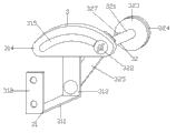
Fig. 2 is the cutter structure schematic diagram of living paper tinsel rolling trimming device described in the utility model;
Fig. 3 is the cutting knife front view of living paper tinsel rolling trimming device described in the utility model.
Among the figure: 1-frame, 2-deflector roll, 3-cutting knife, 21-cutter groove, 31-knife rest, 32-hobboing cutter, the 311-crossbearer, 312-fixed mount, 313-bridge, the ellipse arc platform of 314-, 315-frame groove, 321-knife bar, 322-transfers handle, and the 323-cutter rolls, 324-blade, 325-pylon, 326-draw-in groove, 327-slip screw.
The specific embodiment
Below in conjunction with accompanying drawing the specific embodiment of the present utility model is described in further detail.
Such as Fig. 1, Fig. 2, shown in Figure 3, a kind of living paper tinsel rolling trimming device comprises frame 1, deflector roll 2 and cutting knife 3, wherein deflector roll 2 is cylindrical, can be installed in rotationally on the frame 1, and deflector roll 2 edges at two ends places are provided with cutter groove 21, the both sides of frame 1 are respectively arranged with cutting knife 3.
Embodiment of the present utility model is as follows:
In the present embodiment, cutting knife 3 is comprised of knife rest 31 and hobboing cutter 32, and knife rest 31 is screwed on the frame 1, is fixed with hobboing cutter 32 on the knife rest 31, and this structure is so that whole cutting knife 3 can disassemble from frame convenient for maintaining and replacing.
In the present embodiment, knife rest 31 is welded to form by crossbearer 311, fixed mount 312 and bridge 313, fixed mount 312 is fixed on the frame 1, bridge 313 is weldingly fixed on the fixed mount 312 by crossbearer 311, be arranged so that bridge 313 and the frame 1 of crossbearer 311 form a segment distance, make things convenient for staff to the operation of hobboing cutter 32.
In the present embodiment, be provided with ellipse arc platform 314 on the bridge 313, be provided with frame groove 315 in the middle of the ellipse arc platform 314, frame groove 315 can satisfy the actual adjustment needs of the cutting knife degree of depth.
In the present embodiment, hobboing cutter 32 by knife bar 321, transfer handle 322, cutter roll 323 and pylon 325 be welded to form, pylon 325 upper ends are welded with transfers handle 322 and knife bar 321, and the lower end of pylon 325 can be rotatably fixed to the lower end of bridge 313, the upper end of pylon 325 is by transferring handle 322 to be buckled on the frame groove 315, can regulate knife bar 321 positions by accent handle 322, and then the degree of depth of energy adjustable blade 324.
In the present embodiment, be provided with draw-in groove 326 on the knife bar 321, be provided with slip screw 327 on the draw-in groove 326, and fixedly on the pylon 325, the other end is equipped with cylindrical knife and rolls 323 an end of knife bar 321, and cutter rolls 323 and is welded and fixed by interior bar and slip screw 327, and cutter rolls on 323 the periphery and is provided with blade 324, blade 324 matches with cutter groove 21 on the deflector roll, can regulate the position of hobboing cutter 32 by slip screw 327, and then can regulate the distance of cutting of cutting knife.
That describes in above-described embodiment and the specification just illustrates principle of the present utility model and most preferred embodiment; under the prerequisite that does not break away from the utility model spirit and scope; the utility model also has various changes and modifications, and these changes and improvements all fall in claimed the utility model scope.
Claims (3)
1. living paper tinsel rolling trimming device, comprise frame, deflector roll and two cutting knifes, wherein deflector roll is cylindrical, can be installed in rotationally on the frame, and deflector roll edges at two ends place is provided with the cutter groove, the both sides of frame are respectively arranged with cutting knife, it is characterized in that: described cutting knife is comprised of knife rest and hobboing cutter, hobboing cutter is fixed on the knife rest, knife rest is welded to form by crossbearer, fixed mount and bridge, and fixed mount is screwed on the frame, and bridge is weldingly fixed on the fixed mount by crossbearer, be provided with ellipse arc platform on the bridge, be provided with the frame groove in the middle of the ellipse arc platform; Hobboing cutter by knife bar, transfer handle, cutter rolls is welded to form with pylon, the pylon upper end is welded with transfers handle and knife bar, be provided with draw-in groove on the knife bar, be provided with the slip screw on the draw-in groove, and an end of knife bar is fixed on the pylon, and the other end is equipped with cylindrical knife and rolls, and cutter rolls by interior bar and slip screw and is welded and fixed, be provided with blade on the periphery that cutter rolls, blade matches with cutter groove on the deflector roll.
2. living paper tinsel rolling trimming device according to claim 1, it is characterized in that: the lower end of described pylon can be rotatably fixed to the lower end of bridge, and the upper end of pylon is by transferring handle to be buckled on the frame groove.
3. living paper tinsel rolling trimming device according to claim 1, it is characterized in that: described cutter rolls by the slip screw and is fixed on the knife bar.
Priority Applications (1)
| Application Number | Priority Date | Filing Date | Title |
|---|---|---|---|
| CN 201220319135 CN202684961U (en) | 2012-07-02 | 2012-07-02 | Raw foil rolling edge-cutting device |
Applications Claiming Priority (1)
| Application Number | Priority Date | Filing Date | Title |
|---|---|---|---|
| CN 201220319135 CN202684961U (en) | 2012-07-02 | 2012-07-02 | Raw foil rolling edge-cutting device |
Publications (1)
| Publication Number | Publication Date |
|---|---|
| CN202684961U true CN202684961U (en) | 2013-01-23 |
Family
ID=47540628
Family Applications (1)
| Application Number | Title | Priority Date | Filing Date |
|---|---|---|---|
| CN 201220319135 Expired - Fee Related CN202684961U (en) | 2012-07-02 | 2012-07-02 | Raw foil rolling edge-cutting device |
Country Status (1)
| Country | Link |
|---|---|
| CN (1) | CN202684961U (en) |
Cited By (4)
| Publication number | Priority date | Publication date | Assignee | Title |
|---|---|---|---|---|
| CN103434058A (en) * | 2013-07-06 | 2013-12-11 | 佛山市埃申特科技有限公司 | Edge cutter used for production of charging roller, developing roller, fixing roller and power feeding roller |
| CN106099035A (en) * | 2016-08-19 | 2016-11-09 | 深圳市信宇人科技有限公司 | Lithium is from the roll-in splitting system of the continuous complete automatic assembly line of battery pole piece |
| CN106457593A (en) * | 2016-03-23 | 2017-02-22 | 许长云 | An online edge cutting device of a netting machine |
| CN115026899A (en) * | 2022-06-02 | 2022-09-09 | 永杰新材料股份有限公司 | Battery aluminum foil shearing mechanism |
-
2012
- 2012-07-02 CN CN 201220319135 patent/CN202684961U/en not_active Expired - Fee Related
Cited By (6)
| Publication number | Priority date | Publication date | Assignee | Title |
|---|---|---|---|---|
| CN103434058A (en) * | 2013-07-06 | 2013-12-11 | 佛山市埃申特科技有限公司 | Edge cutter used for production of charging roller, developing roller, fixing roller and power feeding roller |
| CN103434058B (en) * | 2013-07-06 | 2015-06-24 | 佛山市埃申特科技有限公司 | Edge cutter used for production of charging roller, developing roller, fixing roller and power feeding roller |
| CN106457593A (en) * | 2016-03-23 | 2017-02-22 | 许长云 | An online edge cutting device of a netting machine |
| CN106099035A (en) * | 2016-08-19 | 2016-11-09 | 深圳市信宇人科技有限公司 | Lithium is from the roll-in splitting system of the continuous complete automatic assembly line of battery pole piece |
| CN115026899A (en) * | 2022-06-02 | 2022-09-09 | 永杰新材料股份有限公司 | Battery aluminum foil shearing mechanism |
| CN115026899B (en) * | 2022-06-02 | 2023-09-29 | 永杰新材料股份有限公司 | Battery aluminium foil shearing mechanism |
Similar Documents
| Publication | Publication Date | Title |
|---|---|---|
| CN204035664U (en) | A kind of swarf machine | |
| CN202684961U (en) | Raw foil rolling edge-cutting device | |
| CN203919194U (en) | A kind of two-way slitting paper machine | |
| CN103317552B (en) | The processing method of aluminum plastic film slicer and plastic-aluminum diaphragm | |
| CN102861947B (en) | Rotary type manual tubular product cutting device | |
| CN202934635U (en) | Adjustable thin film slitting device | |
| CN203371577U (en) | Sheet splitting machine | |
| CN202633422U (en) | Battery pole ear smoothing cutting machine | |
| CN201720868U (en) | Cutter holder structure for cutting machines | |
| CN211306517U (en) | Blown film side cut device | |
| CN211338158U (en) | Novel lithium battery diaphragm flattening device | |
| CN103433955B (en) | Adjustable wire speed sync cutting knife | |
| CN203140526U (en) | Edge processing device for copper strip for transformer | |
| CN105880720A (en) | Lithium-ion battery pole piece splitting machine | |
| CN203371578U (en) | Slitting device of sheet splitting machine | |
| CN203697102U (en) | Dual-cambered roller device of paper cutting machine | |
| CN203917691U (en) | A kind of feed mechanism of full-automatic numerical control cutter | |
| CN211566038U (en) | Paper tube slitting device | |
| CN203854032U (en) | Reelpipe type waste membrane cutting machine | |
| CN202464869U (en) | Solar glue film radian flattening device | |
| CN202684988U (en) | Hole cutting device for power busbar heat-shrinkable tube | |
| CN202984791U (en) | Edge trimmer | |
| CN207807839U (en) | A kind of foil machine trimming device | |
| CN203126026U (en) | Cutting-off device for sharp-bottomed paper bags | |
| CN203019457U (en) | Edge trimmer for shearing PC (Polycarbonate) board |
Legal Events
| Date | Code | Title | Description |
|---|---|---|---|
| C14 | Grant of patent or utility model | ||
| GR01 | Patent grant | ||
| CF01 | Termination of patent right due to non-payment of annual fee |
Granted publication date: 20130123 Termination date: 20150702 |
|
| EXPY | Termination of patent right or utility model |