CN202675496U - Jet-flow noise-elimination type evaporative cooling air conditioning unit - Google Patents
Jet-flow noise-elimination type evaporative cooling air conditioning unit Download PDFInfo
- Publication number
- CN202675496U CN202675496U CN 201220139876 CN201220139876U CN202675496U CN 202675496 U CN202675496 U CN 202675496U CN 201220139876 CN201220139876 CN 201220139876 CN 201220139876 U CN201220139876 U CN 201220139876U CN 202675496 U CN202675496 U CN 202675496U
- Authority
- CN
- China
- Prior art keywords
- jet
- air
- evaporative cooling
- cooler
- conditioning unit
- Prior art date
- Legal status (The legal status is an assumption and is not a legal conclusion. Google has not performed a legal analysis and makes no representation as to the accuracy of the status listed.)
- Expired - Fee Related
Links
Images

Landscapes
- Other Air-Conditioning Systems (AREA)
Abstract
本实用新型公开了一种射流消声式蒸发冷却空调机组,包括机组壳体一侧壁上设置的进风管a和进风管b,机组壳体顶部设置的排风管以及机组壳体内设置的蒸发冷却装置,蒸发冷却装置内部包括有依次设置的间接蒸发冷却器、直接蒸发冷却器以及送风机,蒸发冷却装置一侧壁与进风管a连接,蒸发冷却装置的另一侧壁上设置有射流送风口,蒸发冷却装置内的间接蒸发冷却器的上部与排风管连接,间接蒸发冷却器的下部与进风管b连接。本实用新型以蒸发冷却空调机组与射流风口相结合为核心,无风管系统,无需单独设置空调机房,可采用吊装的方式安装于室内;二次风可以采用室内回风,也可以采用室外新风,节省了能源。
The utility model discloses a jet flow noise reduction type evaporative cooling air conditioner unit, which comprises an air inlet pipe a and an air inlet pipe b arranged on the side wall of the unit casing, an exhaust pipe arranged on the top of the unit casing, and an air exhaust pipe arranged inside the unit casing. The evaporative cooling device includes an indirect evaporative cooler, a direct evaporative cooler and a blower arranged in sequence inside the evaporative cooling device. One side wall of the evaporative cooling device is connected to the air inlet pipe a, and the other side wall of the evaporative cooling device is provided with The jet air supply port, the upper part of the indirect evaporative cooler in the evaporative cooling device is connected with the exhaust pipe, and the lower part of the indirect evaporative cooler is connected with the air inlet pipe b. The utility model takes the combination of the evaporative cooling air conditioner unit and the jet outlet as the core, has no air duct system, does not need to set up an air conditioner room separately, and can be installed indoors by hoisting; the secondary air can be indoor return air or outdoor fresh air , saving energy.
Description
技术领域 technical field
本实用新型属于空调制冷及流体输送技术领域,涉及一种空气调节装置,具体涉及一种射流消声式蒸发冷却空调机组。The utility model belongs to the technical field of air-conditioning refrigeration and fluid delivery, and relates to an air conditioning device, in particular to a jet-flow noise reduction type evaporative cooling air-conditioning unit.
背景技术 Background technique
如今随着人们对生活和生产环境的要求越来越高,对于工业生产场所的空气处理也越来越得到人们的重视和关注,这就形成了人们对于制冷空气调节设备的需求量呈现成倍增长。随着空调设备的不断发展,其制冷效果已经比较稳定、技术也趋于成熟。但由于空调设备中的制冷剂对环境不友好,会造成臭氧层的破坏,而由于空气调节设备对于电力能源的需求很高,导致了很多地区在夏季出现限电、缺电等现象。Nowadays, as people's requirements for living and production environments are getting higher and higher, people pay more and more attention to the air treatment of industrial production sites, which has caused people's demand for refrigeration and air-conditioning equipment to double. increase. With the continuous development of air-conditioning equipment, its refrigeration effect has been relatively stable, and its technology has become more mature. However, because the refrigerant in the air-conditioning equipment is not friendly to the environment, it will cause the destruction of the ozone layer, and because the air-conditioning equipment has a high demand for electric energy, it has led to power cuts and power shortages in many areas in summer.
蒸发冷却空调是利用可再生能源干空气能的一项技术,主要是依靠环境空气中的干球温度与湿球温度差,通过水与空气之间的热湿交换来获得冷量的一种环保高效且经济的冷却方式,具有节能、环保、经济,健康等特点。蒸发冷却空调目前广泛应用于我国工业车间、农业生产以及商业住宅建筑中。特别是采用直接蒸发冷却技术的蒸发式冷气机、蒸发式空调扇(俗称空调扇)在住宅中应用较为广泛。其初投资及运行成本低廉而且节能环保高效。目前,采用蒸发冷却空调的工程多使用风系统,所以需要单独设置空调机房。Evaporative cooling air conditioning is a technology that uses renewable energy dry air energy. It mainly relies on the difference between the dry bulb temperature and the wet bulb temperature in the ambient air to obtain cooling capacity through the heat and moisture exchange between water and air. Efficient and economical cooling method, with the characteristics of energy saving, environmental protection, economy and health. Evaporative cooling air conditioners are widely used in industrial workshops, agricultural production and commercial residential buildings in my country. In particular, evaporative air conditioners and evaporative air-conditioning fans (commonly known as air-conditioning fans) using direct evaporative cooling technology are widely used in houses. Its initial investment and operation costs are low, and it is energy-saving, environmentally friendly and efficient. At present, projects that use evaporative cooling air-conditioning mostly use wind systems, so it is necessary to set up an air-conditioning room separately.
发明内容 Contents of the invention
本实用新型的目的是提供一种射流消声式蒸发冷却空调机组,将蒸发冷却空调机组与射流风口结合使用,该空调机组结构简单,无风管系统,减少了占地面积,二次风即可采用室内回风,也可采用室外新风,节省了能源。The purpose of this utility model is to provide a jet flow noise-absorbing type evaporative cooling air conditioner unit. The evaporative cooling air conditioner unit is used in combination with the jet outlet. The air conditioner unit has a simple structure and no air duct system, which reduces the occupied area. Indoor return air can be used, and outdoor fresh air can also be used, which saves energy.
本实用新型所采用的技术方案是,一种射流消声式蒸发冷却空调机组,包括机组壳体一侧壁上设置的进风管a和进风管b,机组壳体顶部设置的排风管以及机组壳体内设置的蒸发冷却装置,蒸发冷却装置内部包括有依次设置的间接蒸发冷却器、直接蒸发冷却器以及送风机,蒸发冷却装置一侧壁与进风管a连接,蒸发冷却装置的另一侧壁上设置有射流送风口,蒸发冷却装置内的间接蒸发冷却器的上部与排风管连接,间接蒸发冷却器的下部与进风管b连接。The technical solution adopted by the utility model is a jet-flow noise-absorbing evaporative cooling air-conditioning unit, which includes an air inlet pipe a and an air inlet pipe b arranged on the side wall of the unit casing, and an exhaust pipe arranged on the top of the unit casing And the evaporative cooling device installed in the casing of the unit. The evaporative cooling device includes an indirect evaporative cooler, a direct evaporative cooler and a blower arranged in sequence. One side wall of the evaporative cooling device is connected to the air inlet pipe a, and the other side of the evaporative cooling device A jet air outlet is arranged on the side wall, the upper part of the indirect evaporative cooler in the evaporative cooling device is connected with the exhaust pipe, and the lower part of the indirect evaporative cooler is connected with the air inlet pipe b.
本实用新型的特点还在于,The utility model is also characterized in that,
其中的进风管a管口处设置有进风口a,进风口a后方的进风管a内设置有粗效过滤器a。An air inlet a is arranged at the mouth of the air inlet pipe a, and a coarse-effect filter a is arranged in the air inlet pipe a behind the air inlet a.
其中的进风管b管口处设置有进风口b,进风口b后方的进风管b内设置有粗效过滤器b。An air inlet b is arranged at the mouth of the air inlet pipe b, and a coarse-effect filter b is arranged in the air inlet pipe b behind the air inlet b.
其中的间接蒸发冷却器的结构为:由填料a、填料a下部的蓄水池、填料a上部设置的布水器a组成,蓄水池通过喷淋支管与布水器a连接,喷淋支管上设置有循环水泵a。The structure of the indirect evaporative cooler is: it is composed of filler a, a reservoir under the filler a, and a water distributor a set on the upper part of the filler a. The reservoir is connected to the water distributor a through a spray branch pipe, and the spray branch pipe A circulating water pump a is arranged on it.
其中的直接蒸发冷却器的结构为:由填料b、填料b下部的蓄水池、填料b上部设置的向下喷淋的布水器b组成,蓄水池通过低压供水管与布水器b连接,低压供水管上设置有循环水泵b。The structure of the direct evaporative cooler is as follows: it is composed of filler b, a reservoir at the lower part of filler b, and a downward spraying water distributor b set on the upper part of filler b. The reservoir is connected to the water distributor b through a low-pressure water supply pipe. Connected, the low-pressure water supply pipe is provided with a circulating water pump b.
其中的间接蒸发冷却器采用管式间接蒸发冷却器或板翅式间接蒸发冷却器。The indirect evaporative cooler adopts tube-type indirect evaporative cooler or plate-fin indirect evaporative cooler.
排风管内靠近间接蒸发冷却器的端口处设置有排风机,排风管的另一端口处设置有排风口。An exhaust fan is arranged at the port close to the indirect evaporative cooler in the exhaust pipe, and an air outlet is arranged at the other port of the exhaust pipe.
其中机组壳体内的进风管b一侧设置有回风口。Wherein, one side of the air inlet pipe b in the casing of the unit is provided with an air return port.
其中的射流风口为球形射流风口或射流消声风口。The jet tuyere is a spherical jet tuyere or a jet muffler tuyere.
与目前现有的蒸发冷却空调机组相比,本实用新型具有如下特点:Compared with the existing evaporative cooling air-conditioning units, the utility model has the following characteristics:
1)空调机组与送风射流风口直接结合,省去了送风系统风管,减少成本的同时节省空间。1) The air conditioning unit is directly combined with the air supply jet outlet, which saves the air duct of the air supply system, reduces costs and saves space.
2)由于将蒸发冷却装置与射流风口相结合,所以送风空间大,射程比较远。2) Due to the combination of the evaporative cooling device and the jet air outlet, the air supply space is large and the range is relatively long.
3)该空调机组可以悬挂装于室内,省去单独设置空调机房的占地,可大大节省占地面积。3) The air-conditioning unit can be hung and installed indoors, which saves the land occupation of a separate air-conditioning machine room, which can greatly save the area occupied.
4)送风口具有优良的空气动力性能和一定的消声功能,可使空调房间获得良好的气流分布。4) The air outlet has excellent aerodynamic performance and a certain noise reduction function, which can make the air-conditioned room obtain a good air distribution.
附图说明 Description of drawings
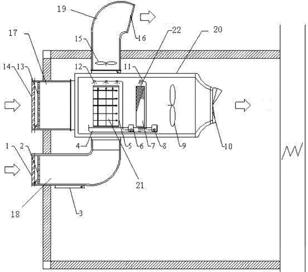
图1是本实用新型空调机组的结构示意图;Fig. 1 is the structural representation of the utility model air-conditioning unit;
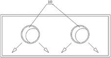
图2是本实用新型空调机组中一种实施例球形射流风口的结构示意图;Fig. 2 is a schematic structural view of an embodiment of a spherical jet tuyere in an air-conditioning unit of the present invention;
图3是本实用新型空调机组中另一种实施例射流消声风口的结构示意图。Fig. 3 is a structural schematic diagram of another embodiment of the jet muffler tuyere in the air conditioning unit of the present invention.
图中,1.进风口b;2.粗效过滤器b;3.回风口;4.蓄水池;5.间接蒸发冷却器;6.水泵;7.直接蒸发冷却器;8.循环水泵a;9.送风机;10.射流风口;11.滴淋喷嘴;12.布水器;13.粗效过滤器a;14.进风口a;15.排风机;16.排风口,17.进风管a,18.进风管b,19.排风管,20.蒸发冷却装置,21.填料a,22.填料b。In the figure, 1. Air inlet b; 2. Coarse effect filter b; 3. Return air outlet; 4. Reservoir; 5. Indirect evaporative cooler; 6. Water pump; 7. Direct evaporative cooler; 8. Circulating water pump a; 9. Blower; 10. Jet outlet; 11. Drip nozzle; 12. Water distributor; 13. Coarse filter a; 14. Air inlet a; 15. Exhaust fan; 16. Exhaust outlet, 17. Air inlet pipe a, 18. air inlet pipe b, 19. exhaust pipe, 20. evaporative cooling device, 21. packing a, 22. packing b.
具体实施方式 Detailed ways
下面结合附图和具体实施方式对本实用新型进行详细说明。The utility model will be described in detail below in conjunction with the accompanying drawings and specific embodiments.
本实用新型射流消声式蒸发冷却空调机组,结构如图1所示,包括机组壳体一侧壁上设置的进风管a17和进风管b18,机组壳体顶部设置的排风管19以及机组壳体内设置的蒸发冷却装置20,蒸发冷却装置20内部包括有依次设置的间接蒸发冷却器5、直接蒸发冷却器7以及送风机9,蒸发冷却装置20一侧壁与进风管a17连接,蒸发冷却装置20的另一侧壁上设置有射流送风口10,蒸发冷却装置20内的间接蒸发冷却器5的上部与排风管19连接,间接蒸发冷却器5的下部与进风管b18连接。The utility model jet flow noise reduction type evaporative cooling air conditioning unit has a structure as shown in Figure 1, including the air inlet pipe a17 and the air inlet pipe b18 arranged on the side wall of the unit casing, the exhaust pipe 19 arranged on the top of the unit casing and The evaporative cooling device 20 is installed in the casing of the unit. The evaporative cooling device 20 includes an indirect evaporative cooler 5, a direct evaporative cooler 7, and a blower 9 arranged in sequence. The other side wall of the cooling device 20 is provided with a
进风管a17管口处设置有进风口a14,进风口a14后方的进风管a17内设置有粗效过滤器a13;进风管b18管口处设置有进风口b1,进风口b1后方的进风管b18内设置有粗效过滤器b2。There is an air inlet a14 at the mouth of the air inlet pipe a17, and a coarse-effect filter a13 is arranged in the air inlet pipe a17 behind the air inlet a14; an air inlet b1 is arranged at the mouth of the air inlet pipe b18, and the air inlet behind the air inlet b1 A coarse-effect filter b2 is arranged in the air duct b18.
间接蒸发冷却器5的结构为:由填料a21、填料a21下部的蓄水池4、填料a21上部设置的布水器a12组成,蓄水池4通过喷淋支管与布水器a12连接,喷淋支管上设置有循环水泵a6。间接蒸发冷却器5采用管式间接蒸发冷却器或板翅式间接蒸发冷却器。The structure of the indirect evaporative cooler 5 is as follows: it is composed of filler a21, the reservoir 4 under the filler a21, and the water distributor a12 set on the upper part of the filler a21. The branch pipe is provided with a circulating water pump a6. The indirect evaporative cooler 5 adopts a tube-type indirect evaporative cooler or a plate-fin indirect evaporative cooler.
直接蒸发冷却器7的结构为:由填料b22、填料b22下部的蓄水池4、填料b22上部设置的向下喷淋的布水器b11组成,蓄水池4通过低压供水管与布水器b11连接,低压供水管上设置有循环水泵b8。The structure of the direct evaporative cooler 7 is as follows: it is composed of filler b22, the reservoir 4 under the filler b22, and the water distributor b11 installed on the upper part of the filler b22 for spraying downwards. b11 is connected, and the low-pressure water supply pipe is provided with a circulating water pump b8.
排风管19的管口上设置有排风口16,间接蒸发冷却器5上部的排风管19内设置有排风机15。An exhaust port 16 is arranged on the nozzle of the exhaust pipe 19 , and an exhaust fan 15 is arranged in the exhaust pipe 19 on the upper part of the indirect evaporative cooler 5 .
机组壳体内的进风管b18一侧设置有回风口3。An air return port 3 is provided on one side of the air inlet pipe b18 in the casing of the unit.
射流风口10可以使用球形射流风口,如图2所示,也可以使用射流消声风口,如图3所示。The
本实用新型射流消声式蒸发冷却空调机组的工作过程:The working process of the jet flow noise reduction evaporative cooling air conditioning unit of the utility model:
当室外新风由进风口a14通过粗效过滤器a13后进行过滤,然后成为一次空气,一次空气被送入间接蒸发冷却器5进行等湿降温,经过间接蒸发冷却器5处理后,空气被继续送入直接蒸发冷却器7内进行等焓降温,最后由送风机9通过射流风口10输送至空调区域。When the outdoor fresh air is filtered through the coarse-effect filter a13 through the air inlet a14, and then becomes primary air, the primary air is sent to the indirect evaporative cooler 5 for isohumidity cooling, and after being processed by the indirect evaporative cooler 5, the air is sent to into the direct evaporative cooler 7 for isenthalpic cooling, and finally transported to the air-conditioning area by the blower 9 through the
采用室内回风作为二次空气时,室内回风通过回风口3进入间接蒸发冷却器5内,然后在间接蒸发冷却器5的二次空气流道中处理后,由排风管内的排风机15通过排风口16排出室外。When the indoor return air is used as the secondary air, the indoor return air enters the indirect evaporative cooler 5 through the return air outlet 3, and then is processed in the secondary air channel of the indirect evaporative cooler 5, and is passed through by the exhaust fan 15 in the exhaust pipe. The air outlet 16 is exhausted to the outside.
采用室外新风作为二次空气时,室外新风通过进风口b1进入粗效过滤器b2过滤后,进入间接蒸发冷却器5,然后在间接蒸发冷却器5的二次空气流道中处理后,由排风机15通过排风口16排出室外。When outdoor fresh air is used as the secondary air, the outdoor fresh air passes through the air inlet b1 and enters the coarse-effect filter b2 to be filtered, then enters the indirect evaporative cooler 5, and then is processed in the secondary air flow channel of the indirect evaporative cooler 5, and is discharged by the exhaust fan 15 is exhausted to the outside through the air outlet 16.
本实用新型以蒸发冷却空调机组与射流风口相结合为核心,设计时可以不用设计独立的空调机房。机组可采用吊装的方式安装于室内。二次风可以采用室内回风,也可以采用室外新风。过渡季节时,可以作为新风组使用。进入进风口的二次空气可以是室外新风,也可以是室内的回风。在间接蒸发冷却器5和直接蒸发冷却器7共用一个蓄水池4。间接蒸发冷却器5内的填料a可以采用纸质、金属、多孔陶瓷或PVC等多种材料。间接蒸发冷却器5可以采用管式间接蒸发冷却器,金属材质,也可以采用板翅式间接蒸发冷却器。整机可直接挂装于室内,不用单独设置空调机房。The utility model takes the combination of the evaporative cooling air-conditioning unit and the jet air outlet as the core, and does not need to design an independent air-conditioning machine room during design. The unit can be installed indoors by hoisting. The secondary air can be indoor return air or outdoor fresh air. During the transition season, it can be used as a fresh air group. The secondary air entering the air inlet can be outdoor fresh air or indoor return air. The indirect evaporative cooler 5 and the direct evaporative cooler 7 share a reservoir 4 . The filler a in the indirect evaporative cooler 5 can adopt multiple materials such as paper, metal, porous ceramics or PVC. The indirect evaporative cooler 5 can be a tube-type indirect evaporative cooler made of metal, or a plate-fin indirect evaporative cooler. The whole machine can be hung indoors directly, without setting up an air-conditioning machine room separately.
Claims (9)
Priority Applications (1)
| Application Number | Priority Date | Filing Date | Title |
|---|---|---|---|
| CN 201220139876 CN202675496U (en) | 2012-04-05 | 2012-04-05 | Jet-flow noise-elimination type evaporative cooling air conditioning unit |
Applications Claiming Priority (1)
| Application Number | Priority Date | Filing Date | Title |
|---|---|---|---|
| CN 201220139876 CN202675496U (en) | 2012-04-05 | 2012-04-05 | Jet-flow noise-elimination type evaporative cooling air conditioning unit |
Publications (1)
| Publication Number | Publication Date |
|---|---|
| CN202675496U true CN202675496U (en) | 2013-01-16 |
Family
ID=47496398
Family Applications (1)
| Application Number | Title | Priority Date | Filing Date |
|---|---|---|---|
| CN 201220139876 Expired - Fee Related CN202675496U (en) | 2012-04-05 | 2012-04-05 | Jet-flow noise-elimination type evaporative cooling air conditioning unit |
Country Status (1)
| Country | Link |
|---|---|
| CN (1) | CN202675496U (en) |
Cited By (5)
| Publication number | Priority date | Publication date | Assignee | Title |
|---|---|---|---|---|
| CN103707740A (en) * | 2013-12-09 | 2014-04-09 | 西安工程大学 | Vehicular evaporative cooling air-conditioning system with cooling capacity gradient utilization function |
| CN105757850A (en) * | 2016-03-18 | 2016-07-13 | 西安工程大学 | Indirect-direct compound evaporative cooling air conditioning unit with multilayer spray type plate pipes |
| CN106545933A (en) * | 2016-10-20 | 2017-03-29 | 西安工程大学 | Industrial premises with jet air port and solar panels direct evaporating-cooling system |
| CN108644941A (en) * | 2018-04-19 | 2018-10-12 | 西安工程大学 | A kind of recovery type heat split-type air conditioner that fresh air purifying is combined with mechanical refrigeration |
| WO2022062413A1 (en) * | 2020-09-24 | 2022-03-31 | 西安工程大学 | Evaporative cooling and seasonal cold storage-based low energy consumption air conditioning cooling system |
-
2012
- 2012-04-05 CN CN 201220139876 patent/CN202675496U/en not_active Expired - Fee Related
Cited By (7)
| Publication number | Priority date | Publication date | Assignee | Title |
|---|---|---|---|---|
| CN103707740A (en) * | 2013-12-09 | 2014-04-09 | 西安工程大学 | Vehicular evaporative cooling air-conditioning system with cooling capacity gradient utilization function |
| CN103707740B (en) * | 2013-12-09 | 2016-01-13 | 西安工程大学 | Utilize the steam cooling mounted air conditioner system of cold step |
| CN105757850A (en) * | 2016-03-18 | 2016-07-13 | 西安工程大学 | Indirect-direct compound evaporative cooling air conditioning unit with multilayer spray type plate pipes |
| CN105757850B (en) * | 2016-03-18 | 2018-10-02 | 西安工程大学 | Multilayer spraying formula plate pipe indirect-direct composite evaporation cooling air conditioning unit |
| CN106545933A (en) * | 2016-10-20 | 2017-03-29 | 西安工程大学 | Industrial premises with jet air port and solar panels direct evaporating-cooling system |
| CN108644941A (en) * | 2018-04-19 | 2018-10-12 | 西安工程大学 | A kind of recovery type heat split-type air conditioner that fresh air purifying is combined with mechanical refrigeration |
| WO2022062413A1 (en) * | 2020-09-24 | 2022-03-31 | 西安工程大学 | Evaporative cooling and seasonal cold storage-based low energy consumption air conditioning cooling system |
Similar Documents
| Publication | Publication Date | Title |
|---|---|---|
| CN203116208U (en) | External cooling type evaporative cooling and mechanical refrigeration combined air-conditioning system for data machine room | |
| CN203893343U (en) | Integrated air conditioning unit combining evaporative cooling and mechanical refrigeration | |
| CN203323274U (en) | Large-small environment evaporative cooling, mechanical cooling and mixed ventilation composite air conditioning system | |
| CN203116200U (en) | Evaporative cooling air-conditioning system applied to datum machine room | |
| CN204084700U (en) | The air-conditioning that the runner being applicable to machine room size environment is combined with evaporative cooling unit | |
| CN203111187U (en) | Evaporative cooling air-conditioning humidity control system with direct evaporative cooling for subway | |
| CN106765793A (en) | Dew point indirect evaporative is cooled down and mechanical refrigeration manifold type energy-saving and purifying air-conditioner set | |
| CN202546965U (en) | Water chilling unit capable of using vertical-type dew-point indirect three-stage evaporative cooling | |
| CN202485130U (en) | Compact type three-level evaporative cooling air conditioning unit | |
| CN202254208U (en) | Direct expansion air conditioning unit with dew-point indirect evaporative cooling air-side economizer | |
| CN102679478A (en) | All-fresh-air type household evaporative-cooling air conditioner window unit | |
| CN204329216U (en) | The integral air conditioner unit that evaporative cooling combines with mechanical refrigeration | |
| CN203385114U (en) | Efficient tubular indirect and direct two-stage evaporative cooling air conditioning unit | |
| CN109990411A (en) | A kind of standpipe indirect evaporating-cooling water cooler of combination gravity assisted heat pipe | |
| CN202403358U (en) | Indirect-direct evaporative cooling air conditioning unit | |
| CN209763378U (en) | Air Conditioning Unit Based on the Combination of Evaporative Cooling and Mechanical Refrigeration | |
| CN203928164U (en) | The humiture that is applicable to frequency conversion machine room is independently controlled vaporizing and cooling air conditioning device | |
| CN206572671U (en) | The energy-saving mechanical cooling couple formula air-conditioner set of dew point indirect evaporative cooling | |
| CN201476191U (en) | An ultra-thin ceiling type evaporative cooling fresh air unit | |
| CN202392921U (en) | Tubular heat recovery type evaporative cooling air-conditioning unit | |
| CN211551913U (en) | Air conditioning unit based on fluorine pump system combined with indirect evaporative cooling | |
| CN205860296U (en) | The refrigeration unit that a kind of evaporative condenser air-conditioning is compound with Water cooled air conditioners | |
| CN209431580U (en) | Dormitory evaporation cooling channel cooling system based on station air-supply | |
| CN204240634U (en) | Be applicable to the gravity heat-pipe type composite evaporation condenser air-conditioning of data center | |
| CN208253835U (en) | A kind of evaporation cooling channel air-conditioning system of combination laminar air-supply |
Legal Events
| Date | Code | Title | Description |
|---|---|---|---|
| C14 | Grant of patent or utility model | ||
| GR01 | Patent grant | ||
| C17 | Cessation of patent right | ||
| CF01 | Termination of patent right due to non-payment of annual fee |
Granted publication date: 20130116 Termination date: 20130405 |