CN202675230U - Lamp capable of aiming at irradiation direction - Google Patents

Lamp capable of aiming at irradiation direction Download PDF

Info

Publication number
CN202675230U
CN202675230U CN 201220244188 CN201220244188U CN202675230U CN 202675230 U CN202675230 U CN 202675230U CN 201220244188 CN201220244188 CN 201220244188 CN 201220244188 U CN201220244188 U CN 201220244188U CN 202675230 U CN202675230 U CN 202675230U
Authority
CN
China
Prior art keywords
lamp
aiming
irradiation direction
lamp body
sight
Prior art date
Legal status (The legal status is an assumption and is not a legal conclusion. Google has not performed a legal analysis and makes no representation as to the accuracy of the status listed.)
Expired - Fee Related
Application number
CN 201220244188
Other languages
Chinese (zh)
Inventor
周明杰
张绍飞
Current Assignee (The listed assignees may be inaccurate. Google has not performed a legal analysis and makes no representation or warranty as to the accuracy of the list.)
Oceans King Lighting Science and Technology Co Ltd
Oceans King Dongguan Lighting Technology Co Ltd
Shenzhen Oceans King Lighting Engineering Co Ltd
Original Assignee
Oceans King Lighting Science and Technology Co Ltd
Oceans King Dongguan Lighting Technology Co Ltd
Shenzhen Oceans King Lighting Engineering Co Ltd
Priority date (The priority date is an assumption and is not a legal conclusion. Google has not performed a legal analysis and makes no representation as to the accuracy of the date listed.)
Filing date
Publication date
Application filed by Oceans King Lighting Science and Technology Co Ltd, Oceans King Dongguan Lighting Technology Co Ltd, Shenzhen Oceans King Lighting Engineering Co Ltd filed Critical Oceans King Lighting Science and Technology Co Ltd
Priority to CN 201220244188 priority Critical patent/CN202675230U/en
Application granted granted Critical
Publication of CN202675230U publication Critical patent/CN202675230U/en
Anticipated expiration legal-status Critical
Expired - Fee Related legal-status Critical Current

Links

Images

Landscapes

  • Non-Portable Lighting Devices Or Systems Thereof (AREA)
  • Fastening Of Light Sources Or Lamp Holders (AREA)

Abstract

本实用新型提供了一种可瞄准照射方向的灯具,包括灯体、固设于所述灯体内的光源以及固设于所述灯体外壁上的瞄准器,所述瞄准器的轴线与所述光源发出的光束的光轴平行。与现有技术相比,本实用新型避免了使用肉眼对灯具进行反复调节,而是采用瞄准器来对灯具的照射方向进行调节,因此调节精度高,安装和调试时间短,工作效率高,本实用新型的灯具尤其适合安装于大型场馆或室外舞台场合。

Figure 201220244188

The utility model provides a lamp capable of aiming an irradiation direction, comprising a lamp body, a light source fixed in the lamp body, and a sight fixed on the outer wall of the lamp body, wherein the axis of the sight is parallel to the optical axis of the light beam emitted by the light source. Compared with the prior art, the utility model avoids repeatedly adjusting the lamp with the naked eye, and instead uses a sight to adjust the irradiation direction of the lamp, so the adjustment accuracy is high, the installation and debugging time is short, and the work efficiency is high. The lamp of the utility model is particularly suitable for installation in large venues or outdoor stages.

Figure 201220244188

Description

A kind of light fixture that aims at direction of illumination
Technical field
The utility model relates to a kind of light fixture, relates in particular to a kind of light fixture that aims at direction of illumination.
Background technology
At present, in large stadium or outdoor stage occasion, when the large-scale light fixture of installment and debugging, need to make with the naked eye the direction of illumination of light fixture is regulated, former thereby can't the direction of illumination of light fixture accurately be regulated because of distance, position height etc., therefore need to repeatedly regulate light fixture, cause installment and debugging to expend for a long time, and the direction of illumination degree of regulation of light fixture be not high.
The utility model content
The purpose of this utility model is to provide a kind of light fixture that aims at direction of illumination, has solved the installment and debugging time length of existing large-scale light fixture and the not high problem of direction of illumination degree of regulation of light fixture.
The utility model is to realize like this, a kind of light fixture that aims at direction of illumination, comprise lamp body, be fixedly arranged on the light source in the described lamp body and be fixedly arranged on sight on the described lamp body outer wall, the axis of described sight is parallel with the optical axis of the light beam that described light source sends.
Particularly, described sight is optical foresight or laser sight.
Particularly, described sight is fixedly arranged on the described lamp body outer wall by a mount pad.
Particularly, offer a mounting groove on the described lamp body outer wall, described mount pad is embedded in the described mounting groove, and described mount pad is fixedly arranged on the described lamp body by at least one securing member, and described sight is fixedly arranged on the described mount pad by some anchor ears.
Particularly, described mount pad is the L-type structure.
Particularly, described securing member is bolt or screw.
Further, be hinged with a mounting bracket on the described lamp body.
Particularly, described light source is halogen tungsten lamp or LED lamp.
Compared with prior art, the present invention has avoided making with the naked eye light fixture has been regulated repeatedly, but adopt sight to come the direction of illumination of light fixture is regulated, therefore degree of regulation is high, the installment and debugging time is short, high efficiency, light fixture of the present invention especially are fit to be installed on large stadium or outdoor stage occasion.
Description of drawings
In order to be illustrated more clearly in the technical solution of the utility model, the below will do to introduce simply to the accompanying drawing of required use among the embodiment, apparently, accompanying drawing in the following describes only is embodiment more of the present utility model, for those of ordinary skills, under the prerequisite of not paying creative work, can also obtain according to these accompanying drawings other accompanying drawing.
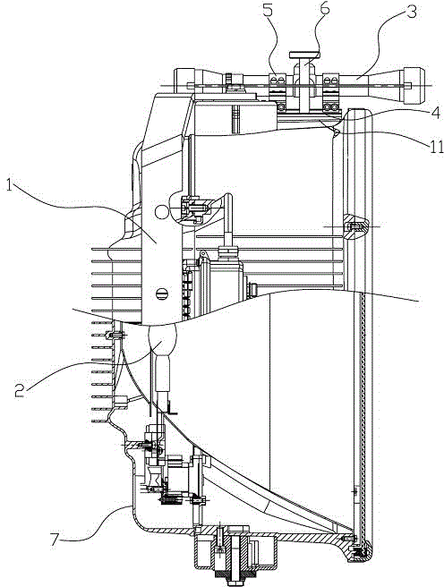
Fig. 1 is the schematic diagram of the light fixture of aimed at the direction of illumination that provides of the utility model embodiment;
Fig. 2 is the schematic diagram of the sight that provides of the utility model embodiment.
The specific embodiment
Below in conjunction with the accompanying drawing among the utility model embodiment, the technical scheme among the utility model embodiment is clearly and completely described.
As depicted in figs. 1 and 2, a kind of light fixture that aims at direction of illumination that the utility model embodiment provides, comprise lamp body 1, be fixedly arranged on the light source 2 in the lamp body 1 and be fixedly arranged on sight 3 on lamp body 1 outer wall, the axis of sight 3 is parallel with the optical axis of the light beam that light source 2 sends.
When the light fixture that aims at direction of illumination of the present invention is carried out installment and debugging, at first rotate lamp body 1, the direction of illumination of light fixture is roughly regulated; Then utilize the direction of illumination of 3 pairs of light fixtures of sight to carry out fine adjustment, until reach required direction of illumination; At last lamp body 1 is fixed, has namely finished the installment and debugging of light fixture.
Compared with prior art, the present invention has avoided making with the naked eye light fixture has been regulated repeatedly, but adopt sight 3 to come the direction of illumination of light fixture is regulated, therefore degree of regulation is high, the installment and debugging time is short, high efficiency, light fixture of the present invention especially are fit to be installed on large stadium or outdoor stage occasion.
Below each part of the utility model is described in detail.
In the present embodiment, described sight 3 is optical foresight or laser sight, adopts optical foresight or laser sight, can accurately regulate the direction of illumination of light fixture.In addition, described light source 2 is halogen tungsten lamp or LED lamp.
As depicted in figs. 1 and 2, the mounting means between described sight 3 and the lamp body 1 is specially: at first, the mount pad 4 of a L-type structure is set; Then, by some anchor ears 5 sight 3 is fixedly arranged on the mount pad 4; Then, offer a mounting groove 11 at the outer wall of lamp body 1; At last, mount pad 4 is embedded in the mounting groove 11, and by at least one securing member 6(such as bolt or screw) mount pad 4 is fixedly arranged on the lamp body 1, thus finished being fixedly connected with of sight 3 and lamp body 1.Because sight 3 is realized and being fixedly connected with of lamp body 1 by mount pad 4, and mount pad 4 can be by the fixing sight 3 of different model and size of anchor ear 5, therefore, the sight 3 of different model and size can be fixed on the lamp body 1 by mount pad 4, is convenient to the user changes different model and size according to operating position sight 3.
As shown in Figure 1, further, be hinged with a mounting bracket 7 on the described lamp body 1, mounting bracket 7 generally is fixedly arranged on the installation positions such as ceiling or mounting, because lamp body 1 is hinged with mounting bracket 7, therefore lamp body 1 is rotated relative to mounting bracket 7, thereby realize the direction of illumination of lamp body 1 is tentatively regulated.
The above is preferred embodiment of the present utility model; should be pointed out that for those skilled in the art, under the prerequisite that does not break away from the utility model principle; can also make some improvements and modifications, these improvements and modifications also are considered as protection domain of the present utility model.

Claims (8)

1.一种可瞄准照射方向的灯具,包括灯体及固设于所述灯体内的光源,其特征在于,还包括固设于所述灯体外壁上的瞄准器,所述瞄准器的轴线与所述光源发出的光束的光轴平行。 1. A lamp capable of aiming at the irradiation direction, comprising a lamp body and a light source fixed in the lamp body, characterized in that it also includes a collimator fixed on the outer wall of the lamp, the axis of the collimator parallel to the optical axis of the light beam emitted by the light source. 2.根据权利要求1所述的一种可瞄准照射方向的灯具,其特征在于,所述瞄准器为光学瞄准器或激光瞄准器。 2 . The lamp capable of aiming at the irradiation direction according to claim 1 , wherein the aimer is an optical aimer or a laser aimer. 3.根据权利要求2所述的一种可瞄准照射方向的灯具,其特征在于,所述瞄准器通过一安装座固设于所述灯体外壁上。 3 . The lamp capable of aiming at the direction of irradiation according to claim 2 , wherein the aimer is fixed on the outer wall of the lamp through a mount. 4 . 4.根据权利要求3所述的一种可瞄准照射方向的灯具,其特征在于,所述灯体外壁上开设有一安装槽,所述安装座嵌设于所述安装槽内,所述安装座通过至少一紧固件固设于所述灯体上,所述瞄准器通过若干抱箍固设于所述安装座上。 4. A lamp capable of aiming at the irradiation direction according to claim 3, wherein a mounting groove is provided on the outer wall of the lamp, and the mounting seat is embedded in the mounting groove, and the mounting seat The aimer is fixed on the lamp body through at least one fastener, and the aimer is fixed on the mounting seat through several hoops. 5.根据权利要求4所述的一种可瞄准照射方向的灯具,其特征在于,所述安装座为L型结构。 5 . The lamp capable of aiming at the irradiation direction according to claim 4 , wherein the mounting seat is an L-shaped structure. 5 . 6.根据权利要求4所述的一种可瞄准照射方向的灯具,其特征在于,所述紧固件为螺栓或螺钉。 6 . The lamp capable of targeting the irradiation direction according to claim 4 , wherein the fastener is a bolt or a screw. 7.根据权利要求1所述的一种可瞄准照射方向的灯具,其特征在于,所述灯体上铰接有一安装支架。 7. The lamp capable of aiming at the irradiation direction according to claim 1, wherein a mounting bracket is hinged on the lamp body. 8.根据权利要求1所述的一种可瞄准照射方向的灯具,其特征在于,所述光源为卤钨灯或LED灯。 8 . The lamp capable of aiming at the irradiation direction according to claim 1 , wherein the light source is a tungsten halogen lamp or an LED lamp.
CN 201220244188 2012-05-29 2012-05-29 Lamp capable of aiming at irradiation direction Expired - Fee Related CN202675230U (en)

Priority Applications (1)

Application Number Priority Date Filing Date Title
CN 201220244188 CN202675230U (en) 2012-05-29 2012-05-29 Lamp capable of aiming at irradiation direction

Applications Claiming Priority (1)

Application Number Priority Date Filing Date Title
CN 201220244188 CN202675230U (en) 2012-05-29 2012-05-29 Lamp capable of aiming at irradiation direction

Publications (1)

Publication Number Publication Date
CN202675230U true CN202675230U (en) 2013-01-16

Family

ID=47496135

Family Applications (1)

Application Number Title Priority Date Filing Date
CN 201220244188 Expired - Fee Related CN202675230U (en) 2012-05-29 2012-05-29 Lamp capable of aiming at irradiation direction

Country Status (1)

Country Link
CN (1) CN202675230U (en)

Cited By (3)

* Cited by examiner, † Cited by third party
Publication number Priority date Publication date Assignee Title
CN103216768A (en) * 2013-03-07 2013-07-24 广州彩熠灯光有限公司 Follow spotlight capable of conveniently aiming and projecting light
CN103363404A (en) * 2013-02-25 2013-10-23 黄�俊 Spotlights
CN113513723A (en) * 2020-06-18 2021-10-19 广东北斗星体育设备有限公司 High-power court lamp of taking infrared sight

Cited By (6)

* Cited by examiner, † Cited by third party
Publication number Priority date Publication date Assignee Title
CN103363404A (en) * 2013-02-25 2013-10-23 黄�俊 Spotlights
CN105090829A (en) * 2013-02-25 2015-11-25 黄�俊 Projection lamp
CN105135301A (en) * 2013-02-25 2015-12-09 黄�俊 Project lamp convenient to regulate
CN103216768A (en) * 2013-03-07 2013-07-24 广州彩熠灯光有限公司 Follow spotlight capable of conveniently aiming and projecting light
CN103216768B (en) * 2013-03-07 2015-05-13 广州彩熠灯光有限公司 Follow spotlight capable of conveniently aiming and projecting light
CN113513723A (en) * 2020-06-18 2021-10-19 广东北斗星体育设备有限公司 High-power court lamp of taking infrared sight

Similar Documents

Publication Publication Date Title
CN103836456B (en) Lamp
CN103836405B (en) Light fixture
CN205278813U (en) Formula LED lamps and lanterns are adjusted to screw
CN202065849U (en) Round LED downlight with height adjustment
CN103712088A (en) Multiple-distribution lamp
CN101737686B (en) Lamp with laser sight
FI20135065A7 (en) Lighting arrangement
CN102980097A (en) A lamp capable of adjusting the projection direction of light source in all directions and from multiple angles
CN218153882U (en) Lamp capable of being adjusted at multiple angles
CN101315166A (en) Floodlight luminaire with adjustable light projector angle
CN216744237U (en) An efficient anti-glare LED flood light
CN107036014B (en) Adjustable LED down lamp
CN108644704A (en) A kind of Projecting Lamp with angle dial
CN204986643U (en) Adjustable LED lamps and lanterns of rocking arm formula
CN204176470U (en) Multifunctional LED invests lamp
CN101598280B (en) A wall washer downlight with adjustable lamp holder position
CN101846292B (en) Light fitting capable of adjusting light source position
CN204328641U (en) One highly regulates light fixture
CN202791678U (en) Light-emitting diode (LED) projection lamp
CN207034778U (en) The embedded adjustable for height projection lamp of one kind
CN203176956U (en) LED (light emitting diode) projection lamp of which irradiation angle can be adjusted through double rotating shafts
CN203549562U (en) Angle-adjustable LED (light-emitting diode) lamp
CN202868505U (en) Adjustable diffuse reflection light beam light-emitting diode (LED) floodlight
TW200710434A (en) Lamp module and projecting apparatus thereof
CN202253243U (en) Anti-glare downlight for easy maintenance

Legal Events

Date Code Title Description
C14 Grant of patent or utility model
GR01 Patent grant
CF01 Termination of patent right due to non-payment of annual fee

Granted publication date: 20130116

Termination date: 20190529