CN202669128U - Film tearing machine - Google Patents
Film tearing machine Download PDFInfo
- Publication number
- CN202669128U CN202669128U CN201220268709.6U CN201220268709U CN202669128U CN 202669128 U CN202669128 U CN 202669128U CN 201220268709 U CN201220268709 U CN 201220268709U CN 202669128 U CN202669128 U CN 202669128U
- Authority
- CN
- China
- Prior art keywords
- film
- optical film
- protective film
- coating
- removing machine
- Prior art date
- Legal status (The legal status is an assumption and is not a legal conclusion. Google has not performed a legal analysis and makes no representation as to the accuracy of the status listed.)
- Expired - Fee Related
Links
Images

Classifications
-
- Y—GENERAL TAGGING OF NEW TECHNOLOGICAL DEVELOPMENTS; GENERAL TAGGING OF CROSS-SECTIONAL TECHNOLOGIES SPANNING OVER SEVERAL SECTIONS OF THE IPC; TECHNICAL SUBJECTS COVERED BY FORMER USPC CROSS-REFERENCE ART COLLECTIONS [XRACs] AND DIGESTS
- Y02—TECHNOLOGIES OR APPLICATIONS FOR MITIGATION OR ADAPTATION AGAINST CLIMATE CHANGE
- Y02W—CLIMATE CHANGE MITIGATION TECHNOLOGIES RELATED TO WASTEWATER TREATMENT OR WASTE MANAGEMENT
- Y02W30/00—Technologies for solid waste management
- Y02W30/50—Reuse, recycling or recovery technologies
- Y02W30/62—Plastics recycling; Rubber recycling
Landscapes
- Application Of Or Painting With Fluid Materials (AREA)
Abstract
本实用新型提供了一种撕膜机,用于撕除光学膜材的保护膜,其包括:撕膜构件,所述撕膜构件包括连接所述保护膜的保护膜转轴、及连接所述保护膜转轴的第一驱动电机,所述第一驱动电机驱动所述保护膜转轴转动,以将保护膜卷设于所述保护膜转轴上;支架,用于支承所述撕膜构件及光学膜材。与现有技术相比,本实用新型所提供的撕膜机,可自动将光学膜材上下表面的保护膜撕除,避免人工撕膜所造成的光学膜材质量问题,提高了产品的良品率,同时方便光学膜材进行后续的加工,提高了加工效率并降低了人工成本,并且适应光学膜材的多种组装方式,具有很高的定制能力。
The utility model provides a film tearing machine, which is used for tearing off the protective film of an optical film material. The first driving motor of the film rotating shaft, the first driving motor drives the rotating shaft of the protective film to rotate the protective film on the rotating shaft of the protective film; the bracket is used to support the tearing film member and the optical film material . Compared with the prior art, the film tearing machine provided by the utility model can automatically tear off the protective film on the upper and lower surfaces of the optical film material, avoiding the quality problems of the optical film material caused by manual tearing of the film, and improving the yield of the product , and at the same time facilitate the subsequent processing of optical film materials, improve processing efficiency and reduce labor costs, and adapt to various assembly methods of optical film materials, with high customization capabilities.
Description
技术领域 technical field
本实用新型涉及机械设备领域,尤其涉及一种撕去光学膜材表面保护膜的撕膜机。 The utility model relates to the field of mechanical equipment, in particular to a film tearing machine for tearing off a protective film on the surface of an optical film material.
背景技术 Background technique
光学膜材的表面一般都会贴附一层保护膜,以避免光学膜材被损坏,也避免工作环境中空气中的微粒或尘埃掉落进光学膜材中而引发质量问题。 A protective film is generally attached to the surface of the optical film to prevent the optical film from being damaged, and to prevent particles or dust in the air from falling into the optical film in the working environment and causing quality problems.
现有的光学膜材在组装时,需先将此保护膜撕下才可进行后续处理,当前主要采用人工来撕除光学膜材的保护膜,增加了操作人员的工作量,并极易因施工人员技术、经验的不足导致施工不精准,从而造成施工品质问题,同时导致了工作效率的降低以及人工成本的上升,无法形成市场竞争优势,同时人工撕除保护膜仅适用于光学膜材组装结构较为简单的形式,如果光学膜材的组装结构过于复杂,人工撕除保护膜的难度也将增加,导致生产效率的降低。 When the existing optical film materials are assembled, the protective film needs to be torn off before subsequent processing. At present, the protective film of the optical film materials is mainly removed manually, which increases the workload of the operators and is easily caused by Insufficient technology and experience of construction personnel lead to inaccurate construction, which leads to construction quality problems, and at the same time leads to a decrease in work efficiency and an increase in labor costs, which cannot form a market competitive advantage. At the same time, manual tearing of the protective film is only suitable for optical film assembly In the form of a relatively simple structure, if the assembly structure of the optical film is too complicated, the difficulty of manually tearing off the protective film will also increase, resulting in a decrease in production efficiency.
因此有必要提出一种撕膜机来解决上述问题。 Therefore it is necessary to propose a film tearing machine to solve the above problems.
发明内容 Contents of the invention
本实用新型提供了一种撕除保护膜效率高并适用于多种保护膜组装方式的撕膜机。 The utility model provides a film tearing machine which has high efficiency of tearing off a protective film and is suitable for various protective film assembly methods.
为达到上述实用新型目的,本实用新型提供了一种撕膜机,用于撕除光学膜材的保护膜,其包括: In order to achieve the purpose of the above-mentioned utility model, the utility model provides a film tearing machine for tearing off the protective film of the optical film material, which includes:
撕膜构件,所述撕膜构件包括连接所述保护膜的保护膜转轴、及连接所述保护膜转轴的第一驱动电机,所述第一驱动电机驱动所述保护膜转轴转动,以将保护膜卷设于所述保护膜转轴上; A tearing film member, the tearing film member includes a protective film rotating shaft connected to the protective film, and a first drive motor connected to the protective film rotating shaft, the first driving motor drives the protective film rotating shaft to rotate, so as to protect the The film roll is arranged on the protective film rotating shaft;
支架,用于支承所述撕膜构件及光学膜材。 The bracket is used to support the tearing film member and the optical film material.
作为本实用新型的进一步改进,所述撕膜构件还包括胶带出轴、及设置于所述胶带出轴上并绕经所述保护膜转轴的胶带,所述胶带粘合所述保护膜。 As a further improvement of the present utility model, the film tearing member further includes a tape output shaft, and an adhesive tape disposed on the tape output shaft and wound around the protective film shaft, and the adhesive tape adheres to the protective film.
作为本实用新型的进一步改进,所述撕膜构件包括连接所述胶带出轴的第二驱动电机,以控制所述胶带出轴转动。 As a further improvement of the present invention, the film tearing member includes a second drive motor connected to the tape output shaft to control the rotation of the tape output shaft.
作为本实用新型的进一步改进,所述第一驱动电机与第二驱动电机控制所述保护膜转轴与所述胶带出轴朝向相反的方向转动。 As a further improvement of the present invention, the first drive motor and the second drive motor control the rotating shaft of the protective film and the output shaft of the adhesive tape to rotate in opposite directions.
作为本实用新型的进一步改进,所述撕膜构件都包括一剥料板,所述剥料板抵持所述保护膜,以使得所述保护膜脱离光学膜材表面。 As a further improvement of the present invention, the film tearing members all include a stripping plate, and the stripping plate presses against the protective film so that the protective film is separated from the surface of the optical film.
作为本实用新型的进一步改进,所述撕膜机包括用于放置光学膜材的放料构件、以及设置于放料构件周侧的挡料构件,以限定光学膜材位置。 As a further improvement of the utility model, the film tearing machine includes a discharge member for placing the optical film material, and a material stop member arranged around the discharge member to limit the position of the optical film material.
作为本实用新型的进一步改进,所述撕膜机包括连接所述放料构件的第三驱动电机,以控制所述放料构件移动至工位。 As a further improvement of the present utility model, the film tearing machine includes a third drive motor connected to the discharging member to control the discharging member to move to a working position. the
作为本实用新型的进一步改进,所述放料构件包括放料板以及放料筒。 As a further improvement of the utility model, the discharging member includes a discharging plate and a discharging cylinder.
作为本实用新型的进一步改进,所述撕膜机包括下压滚轮,所述下压滚轮压持所述光学膜材的保护膜。 As a further improvement of the utility model, the film tearing machine includes a pressing roller, and the pressing roller presses the protective film of the optical film material. the
作为本实用新型的进一步改进,所述撕膜机包括两个分离设置的撕膜构件,以分别撕除光学膜材的上保护膜与下保护膜。 As a further improvement of the present utility model, the film tearing machine includes two film tearing members separately arranged to tear off the upper protective film and the lower protective film of the optical film material respectively.
与现有技术相比,本实用新型所提供的撕膜机,可自动将光学膜材上下表面的保护膜撕除,避免人工撕膜所造成的光学膜材质量问题,提高了产品的良品率,同时方便光学膜材进行后续的加工,提高了加工效率并降低了人工成本,并且适应光学膜材的多种组装方式,具有很高的定制能力。 Compared with the prior art, the film tearing machine provided by the utility model can automatically tear off the protective film on the upper and lower surfaces of the optical film material, avoiding the quality problems of the optical film material caused by manual tearing of the film, and improving the yield of the product , and at the same time facilitate the subsequent processing of optical film materials, improve processing efficiency and reduce labor costs, and adapt to various assembly methods of optical film materials, with high customization capabilities.
附图说明 Description of drawings
为了更清楚地说明本实用新型实施例或现有技术中的技术方案,下面将对实施例或现有技术描述中所需要使用的附图作简单地介绍,显而易见地,下面描述中的有关本实用新型的附图仅仅是本实用新型的一些实施例,对于本领域普通技术人员来讲,在不付出创造性劳动的前提下,还可以根据这些附图获得其他的附图。 In order to more clearly illustrate the technical solutions in the embodiments of the present invention or the prior art, the accompanying drawings that need to be used in the description of the embodiments or the prior art will be briefly introduced below. The drawings of the utility model are only some embodiments of the utility model, and those skilled in the art can also obtain other drawings according to these drawings without creative work.
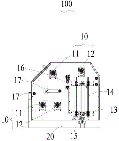
图1为本实用新型一实施例中撕膜机的截面图; Fig. 1 is a sectional view of a film tearing machine in an embodiment of the utility model;
图2为本实用新型另一实施例中撕膜机的截面图。 Fig. 2 is a cross-sectional view of a film tearing machine in another embodiment of the present invention.
其中,附图标记为: Wherein, reference sign is:
撕膜机,100;撕膜构件,10;支架,20;保护膜转轴,11;胶带出轴,12;放料构件,13;挡料构件,14;第三驱动电机,15;下压滚轮,16;剥料板,17。 Film tearing machine, 100; film tearing member, 10; bracket, 20; protective film rotating shaft, 11; , 16; stripping plate, 17.
具体实施方式 Detailed ways
以下将结合附图所示的各实施例对本实用新型进行详细描述。但这些实施例并不限制本实用新型,本领域的普通技术人员根据这些实施例所做出的结构、方法、或功能上的变换均包含在本实用新型的保护范围内。 The utility model will be described in detail below in conjunction with various embodiments shown in the accompanying drawings. But these embodiments do not limit the present utility model, and the structural, method, or functional changes made by those skilled in the art according to these embodiments are all included in the protection scope of the present utility model.
本实用新型所提供了一种撕膜机100,用以撕除光学膜材表面之保护膜,其具体包括:
The utility model provides a
撕膜构件10,前述撕膜构件10包括连接光学膜材保护膜的保护膜转轴11、及连接保护膜转轴11的第一驱动电机,所述第一驱动电机驱动保护膜转轴11转动,以将保护膜卷于保护膜转轴11上;以及支架20,用于支承所述撕膜构件10及光学膜材。
Tear
本实用新型通过可旋转的保护膜转轴11带动保护膜脱离光学膜材表面。
The utility model drives the protective film to separate from the surface of the optical film material through the rotatable protective
参图1所示,本实用新型的一个实施例中,撕膜构件10还包括胶带出轴12、及设置于胶带出轴12上并绕经保护膜转轴11的胶带,胶带用于粘合保护膜。
Referring to shown in Fig. 1, in one embodiment of the present utility model,
特别的,撕膜机包括两个分离设置的撕膜构件10,通过两个撕膜构件10相配合可同步撕除光学膜材上保护膜与下保护膜。
In particular, the film tearing machine includes two separate
其中,胶带为一胶带卷,其主体部设置于胶带出轴12上,并可绕胶带出轴12转动,胶带自主体部延伸出来,并绕经于保护膜转轴11上。
Wherein, adhesive tape is an adhesive tape roll, and its main part is arranged on the adhesive
胶带通过胶带出轴12与保护膜转轴11配合转动来移动,从而带动胶带所粘合的保护膜移动,以使得保护膜脱离光学膜材表面。
The adhesive tape moves through the cooperating rotation of the adhesive
本实用新型通过两个撕膜构件10中的两个胶带分别粘合光学膜材的上保护膜与下保护膜,以同步撕除光学膜材的上保护膜与下保护膜,提高撕膜效率以及精度。
The utility model respectively bonds the upper protective film and the lower protective film of the optical film material through two adhesive tapes in the two tearing
具体的,撕膜构件10包括分别连接所述保护膜转轴11与所述胶带出轴12的第一驱动电机与第二驱动电机,第一驱动电机与第二驱动电机相配合以控制所述保护膜转轴11与所述胶带出轴12转动,从而带动胶带发生移动,便于后续的撕膜处理。
Specifically, the
其中,第一驱动电机所提供的转轴驱动力为主动力,前述保护膜转轴11转动以收卷胶带,由于胶带出轴12与保护膜转轴11之间有胶带的存在,第一驱动电机所提供的转轴驱动力为也带动胶带出轴12转动,使得胶带不断被补充进来,从而满足工业制备过程需要。
Wherein, the driving force of the rotating shaft provided by the first driving motor is the main driving force, and the aforementioned protective
特别的,所述第二驱动电机控制所述胶带出轴12朝向与所述保护膜转轴11相反的方向转动,即第二驱动电机提供了与第一驱动电机所提供转轴驱动力方向相反的张力,该张力的大小远小于前述转轴驱动力,从而不影响胶带自胶带出轴12移动至保护膜转轴11,同时,该张力还使得胶带在移动过程中也能保持一定的紧绷度,提高了胶带与光学膜材表面保护膜之间的粘合能力,以使得保护膜顺利跟随胶带移动至保护膜转轴11上,从而完成撕膜处理。
In particular, the second drive motor controls the
撕膜构件10包括剥料板17,以抵持光学膜材的保护膜,具体的,剥料板17与撕膜构件10数量一致,也设置为两个,所述两个剥料板17板分别抵持光学膜材的上保护膜与下保护膜,以使得所述上保护膜与下保护膜脱离光学膜材表面。
The
剥料板17设置于光学膜材移动的路径上,并且上保护膜或下保护膜在移动过程中,为前述两个剥料板17分别抵持。
The
具体的,剥料板17将保护膜朝向光学膜材主材层挤压,而保护膜撕离光学膜材的过程中,是远离光学膜材主材层移动的,因而,剥料板17可以定义保护膜初始脱离光学膜材的位置,提高撕离上保护膜或下保护膜的效率与精度。
Specifically, the
撕膜机100还包括下压滚轮16,下压滚轮16压持所述光学膜材的保护膜,以使得在撕膜过程中,保护膜具有一定的紧绷度,使得撕膜过程更简单。
The
具体的,下压滚轮16轻压光学膜材的上保护膜,同时保护膜在撕离过程中,可带动下压滚轮16转动,在不降低对保护膜压持力的同时提高了撕离上保护膜的安全性,避免损坏光学膜材,其中,下压滚轮16通过气缸驱动。
Specifically, the
撕膜机100还包括用于放置光学膜材的放料构件13、以及设置于放料构件13周侧的挡料构件14,以限定光学膜材位置。
The
特别的,放料构件13包括放料板以及放料圆筒,以适应多种组装形式之光学膜材。
In particular, the
具体的,光学膜材放置于放料构件13后,挡料构件14移动至相应位置,以使得光学膜材不会因为撕膜处理而位置有过大的变化,避免了因光学膜材移动所引发的一系列光学膜材质量问题。
Specifically, after the optical film material is placed on the
撕膜机100包括保护膜收容构件,以收容自光学膜材表面脱离保护膜,方便在撕膜处理结束后,对上保护膜与下保护膜进行处理、以使得撕膜机100可以准备后续的撕膜工作,进一步的提高撕膜效率。
The
以下结合实际应用中所需撕膜的光学膜材的组装形式,具体描述撕膜机100的三种实施例:
Three embodiments of the
1.若所需撕膜的光学膜材为片料形式,应预先将片料光学膜材放置于放料构件13上,在调整挡料构件14以限定光学膜材位置,然后开启连接装放构件13的第三驱动电机15,以使放料构件13向上运动,从而使得单片光学膜材粘到胶带上,继而为胶带所转载,以准备后续的撕膜处理。
1. If the optical film to be torn off is in the form of a sheet, the sheet optical film should be placed on the
具体的,所述放料构件13为放料板。
Specifically, the discharging
进而,每个撕膜构件10中胶带出轴12都装配一卷胶带,胶带通过连接轴连接到保护膜转轴11,这样,当片料光学膜材粘到胶带上后,第一驱动电机与第二驱动电机配合带动胶带的运动,进而实现光学膜材的转载。
And then,
其中第一驱动电机提供光学膜材转载的主动力,胶带出轴12的第二驱动电机提供反方向上的张力,以使得胶带保持一定程度的紧绷度,以使得胶带与保护膜的粘合更紧密。
Wherein the first drive motor provides the main power for the optical film material to be transferred, and the second drive motor of the
在光学膜材的保护膜移动至对应位置的剥料板17所在位置时,由于受到剥料板17的抵持,保护膜被撕离光学膜材表面,进而完成保护膜撕离处理。
When the protective film of the optical film moves to the corresponding position of the stripping
本实施例中,保护膜收容构件即保护膜转轴11,撕下的保护膜卷入保护膜转轴11上。
In this embodiment, the protective film containing member is the protective
完成上述过程后,第三驱动电机15带动放料构件13上移入工位,使得未撕除保护膜的片料光学膜材自动化进行撕膜处理。
After the above process is completed, the
2.若所需撕膜的光学膜材为叠料形式,在撕膜处理前,应预先将叠料形式的光学膜材放在放料构件13上,再调整挡料构件14以限定光学膜材位置,保护膜转轴11转动以带动上保护膜与下保护膜移动,由下压滚轮压附光学膜材反方向张力,为后续自动撕膜做准备。
2. If the optical film material of the desired tear film is in the form of a laminate, before the tear film is processed, the optical film material in the form of a laminate should be placed on the
具体的,所述放料构件13为放料板。
Specifically, the discharging
此处的叠料形式的光学膜材包括:至少两个主体部;及设置于相邻主体部之间的翻折部,所述主体部通过所述翻折部实现堆叠,其中,只有相邻主体部互相抵持。 The laminated optical film material here comprises: at least two main body parts; The main parts are against each other.
具体的,叠料光学膜材包括设置于首尾的第一主体部与第二主体部,以及设置于第一主体部与第二主体部之间的中间主体部,叠料光学膜材堆叠后,中间主体部都位于第一主体部与第二主体部之间,即,叠料光学膜材的第一主体部与第二主体部分别设置于光学膜材的上下两侧,以构成叠料光学膜材的上下两侧面。 Specifically, the laminated optical film material includes a first main body portion and a second main body portion arranged at the head and tail, and an intermediate main body portion disposed between the first main body portion and the second main body portion. After the laminated material optical film material is stacked, The middle body parts are all located between the first body part and the second body part, that is, the first body part and the second body part of the laminated optical film material are respectively arranged on the upper and lower sides of the optical film material to form a laminated optical film. The upper and lower sides of the membrane.
针对前述叠料形式的光学膜材,撕膜机100的保护膜转轴11连接光学膜材的保护膜,此处不使用胶带来实现撕膜。
For the aforementioned laminated optical film material, the protective
特别的,保护膜转轴11具有两个,分别对应撕除光学膜材的上保护膜与下保护膜。
In particular, there are two protective
其中,第一驱动电机提供光学膜材转载的主动力,下压滚轮16通过压持光学膜材的保护膜以使得保护膜具有反方向上的张力,使得保护膜紧绷,从而保证撕膜工作的顺利进行。
Wherein, the first drive motor provides the main force for the reprinting of the optical film material, and the
具体的,两个第一驱动电机带动两个保护膜转轴11转动,以带动上保护膜与下保护膜脱离光学膜材表面,从而完成撕膜处理。
Specifically, the two first driving motors drive the two protective
本实施例中,保护膜收容构件即保护膜转轴11,撕下的保护膜卷入保护膜转轴11上。
In this embodiment, the protective film containing member is the protective
由于叠料光学膜材为一体式设计,可自动重复前述进程,完成对整个叠料光学膜材之撕膜处理。 Due to the integrated design of the laminated optical film, the aforementioned process can be repeated automatically to complete the tearing process of the entire laminated optical film.
3. 参图2所示,若所需撕膜的光学膜材为卷料形式,撕膜机100中放料构件13为装料圆筒,该装料筒包括一个外套筒、及一个四连杆机构,通过四连杆机构可完成装料筒的夹紧及放松动作,从而方便进行装入与取出卷料光学膜材。
3. As shown in Figure 2, if the optical film material to be torn off is in roll form, the discharging
卷料光学膜材的上保护膜与下保护膜被撕离后收容于保护膜转轴11上。
The upper protective film and the lower protective film of the roll optical film material are torn off and stored on the protective
具体的,保护膜转轴11为保护膜滚筒,包括一个内套筒、一个外套筒及四块钢片,钢片固定于外套筒,内外套筒产生相对运动控制钢片上升与下降达到套筒直径可变的目的,使得卷紧的保护膜可轻松拆卸。
Specifically, the protective
上保护膜与下保护膜卷于保护膜转轴11之上,转动保护膜转轴11,从而带动卷料形式光膜材料转动以完成撕膜动作。
The upper protective film and the lower protective film are rolled on the protective
与现有技术相比,本实用新型所提供的撕膜机100,可自动将光学膜材上下表面的保护膜撕除,避免人工撕膜所造成的光学膜材质量问题,提高了产品的良品率,同时方便光学膜材进行后续的加工,提高了加工效率并降低了人工成本,并且适应光学膜材的多种组装方式,具有很高的定制能力,有利于形成产品竞争优势。
Compared with the prior art, the
应当理解,虽然本说明书按照实施方式加以描述,但并非每个实施方式仅包含一个独立的技术方案,说明书的这种叙述方式仅仅是为清楚起见,本领域技术人员应当将说明书作为一个整体,各实施方式中的技术方案也可以经适当组合,形成本领域技术人员可以理解的其他实施方式。 It should be understood that although this description is described according to implementation modes, not each implementation mode only contains an independent technical solution, and this description in the description is only for clarity, and those skilled in the art should take the description as a whole, and each The technical solutions in the embodiments can also be properly combined to form other embodiments that can be understood by those skilled in the art.
上文所列出的一系列的详细说明仅仅是针对本实用新型的可行性实施方式的具体说明,它们并非用以限制本实用新型的保护范围,凡未脱离本实用新型技艺精神所作的等效实施方式或变更均应包含在本实用新型的保护范围之内。 The series of detailed descriptions listed above are only specific descriptions for the feasible implementation modes of the present utility model, and they are not used to limit the protection scope of the present utility model. Embodiments or modifications should be included within the protection scope of the present utility model.
Claims (10)
Priority Applications (1)
| Application Number | Priority Date | Filing Date | Title |
|---|---|---|---|
| CN201220268709.6U CN202669128U (en) | 2012-06-08 | 2012-06-08 | Film tearing machine |
Applications Claiming Priority (1)
| Application Number | Priority Date | Filing Date | Title |
|---|---|---|---|
| CN201220268709.6U CN202669128U (en) | 2012-06-08 | 2012-06-08 | Film tearing machine |
Publications (1)
| Publication Number | Publication Date |
|---|---|
| CN202669128U true CN202669128U (en) | 2013-01-16 |
Family
ID=47490058
Family Applications (1)
| Application Number | Title | Priority Date | Filing Date |
|---|---|---|---|
| CN201220268709.6U Expired - Fee Related CN202669128U (en) | 2012-06-08 | 2012-06-08 | Film tearing machine |
Country Status (1)
| Country | Link |
|---|---|
| CN (1) | CN202669128U (en) |
Cited By (4)
| Publication number | Priority date | Publication date | Assignee | Title |
|---|---|---|---|---|
| CN103223765A (en) * | 2013-03-07 | 2013-07-31 | 京东方科技集团股份有限公司 | Membrane stripping apparatus |
| CN103465603A (en) * | 2012-06-08 | 2013-12-25 | 京东方科技集团股份有限公司 | Film tearing machine |
| CN103522728A (en) * | 2013-07-31 | 2014-01-22 | 深圳市永能机械有限公司 | Automatic adhesive tearing-off equipment and method |
| CN107449785A (en) * | 2017-08-02 | 2017-12-08 | 苏州市朗电机器人有限公司 | A kind of Visual intelligent testing agency of optical film |
-
2012
- 2012-06-08 CN CN201220268709.6U patent/CN202669128U/en not_active Expired - Fee Related
Cited By (9)
| Publication number | Priority date | Publication date | Assignee | Title |
|---|---|---|---|---|
| CN103465603A (en) * | 2012-06-08 | 2013-12-25 | 京东方科技集团股份有限公司 | Film tearing machine |
| CN103465603B (en) * | 2012-06-08 | 2016-03-30 | 京东方科技集团股份有限公司 | Coating-removing machine |
| CN103223765A (en) * | 2013-03-07 | 2013-07-31 | 京东方科技集团股份有限公司 | Membrane stripping apparatus |
| CN103223765B (en) * | 2013-03-07 | 2015-12-09 | 京东方科技集团股份有限公司 | Membrane stripping device |
| US9623647B2 (en) | 2013-03-07 | 2017-04-18 | Boe Technology Group Co., Ltd. | Film stripping apparatus |
| CN103522728A (en) * | 2013-07-31 | 2014-01-22 | 深圳市永能机械有限公司 | Automatic adhesive tearing-off equipment and method |
| CN103522728B (en) * | 2013-07-31 | 2015-08-12 | 深圳市永能机械有限公司 | Automatically gluing equipment and method is taken off |
| CN107449785A (en) * | 2017-08-02 | 2017-12-08 | 苏州市朗电机器人有限公司 | A kind of Visual intelligent testing agency of optical film |
| CN107449785B (en) * | 2017-08-02 | 2020-03-17 | 苏州市朗电机器人有限公司 | Visual intelligent detection mechanism for optical film |
Similar Documents
| Publication | Publication Date | Title |
|---|---|---|
| CN204802700U (en) | Automatic change of lap device unreels | |
| CN106395485B (en) | A kind of decentralized gummed paper automatic laminating machine utilizing | |
| CN102646851B (en) | Battery core lamination machine of lithium battery | |
| CN107934015B (en) | Automatic double-sided continuous film laminating equipment for LCD screen | |
| CN105375058B (en) | Battery core glue plastering machine | |
| CN206336821U (en) | Composite packaging film cutting machine | |
| CN211685972U (en) | A device for tearing film and sticking film | |
| CN106335666A (en) | An online laminating machine | |
| CN109592110B (en) | Film collection device | |
| CN203079372U (en) | Novel splitting machine | |
| CN108749273A (en) | A kind of coat peeling unit and dyestripping method removed for plate-like product surface film | |
| CN205257582U (en) | Automatic paper equipment that connects of gypsum board mask paper | |
| CN201960799U (en) | Automatic sticking film machine for front and back of mobile phone shell | |
| CN103465603B (en) | Coating-removing machine | |
| CN202156824U (en) | Double sticky tape adhering device | |
| CN102646849A (en) | Battery core laminating machine of lithium battery and membrane unreeling device | |
| CN207368135U (en) | A kind of adhesive paper equipment | |
| CN105314452A (en) | Optical clear adhesive film separating mechanism in laminating machine | |
| CN107732309B (en) | Adhesive tape sticking equipment | |
| CN101265932B (en) | Adhesive bonder | |
| CN103395274B (en) | Gluing film laminating device of drum type laminating machine | |
| CN116080250A (en) | Tear film device | |
| CN103824990B (en) | The two-sided automatic laminating machine utilizing of cell connector | |
| CN209113180U (en) | Multistation winder bottom corrugationless film cutting mechanism | |
| CN205204447U (en) | Optics double faced adhesive tape is from membrane mechanism in rigging machine |
Legal Events
| Date | Code | Title | Description |
|---|---|---|---|
| C14 | Grant of patent or utility model | ||
| GR01 | Patent grant | ||
| C56 | Change in the name or address of the patentee | ||
| CP01 | Change in the name or title of a patent holder |
Address after: 100015 Jiuxianqiao Road, Beijing, No. 10, No. Patentee after: BOE Technology Group Co., Ltd. Patentee after: BOE Optical Science and Technology Co., Ltd. Address before: 100015 Jiuxianqiao Road, Beijing, No. 10, No. Patentee before: BOE Technology Group Co., Ltd. Patentee before: Suzhou Jingdongfang Chagu Electronics Co., Ltd. |
|
| CF01 | Termination of patent right due to non-payment of annual fee |
Granted publication date: 20130116 Termination date: 20210608 |
|
| CF01 | Termination of patent right due to non-payment of annual fee |