CN202662960U - Terminal crimping die - Google Patents

Terminal crimping die Download PDF

Info

Publication number
CN202662960U
CN202662960U CN201220315282.0U CN201220315282U CN202662960U CN 202662960 U CN202662960 U CN 202662960U CN 201220315282 U CN201220315282 U CN 201220315282U CN 202662960 U CN202662960 U CN 202662960U
Authority
CN
China
Prior art keywords
crimping
module
lifting rod
terminal
base
Prior art date
Legal status (The legal status is an assumption and is not a legal conclusion. Google has not performed a legal analysis and makes no representation as to the accuracy of the status listed.)
Withdrawn - After Issue
Application number
CN201220315282.0U
Other languages
Chinese (zh)
Inventor
黄继平
刁忠亮
Current Assignee (The listed assignees may be inaccurate. Google has not performed a legal analysis and makes no representation or warranty as to the accuracy of the list.)
SHANGHAI KEY-SOLUTION ELECTRONIC TECHNOLOGY Co Ltd
Original Assignee
SHANGHAI KEY-SOLUTION ELECTRONIC TECHNOLOGY Co Ltd
Priority date (The priority date is an assumption and is not a legal conclusion. Google has not performed a legal analysis and makes no representation as to the accuracy of the date listed.)
Filing date
Publication date
Application filed by SHANGHAI KEY-SOLUTION ELECTRONIC TECHNOLOGY Co Ltd filed Critical SHANGHAI KEY-SOLUTION ELECTRONIC TECHNOLOGY Co Ltd
Priority to CN201220315282.0U priority Critical patent/CN202662960U/en
Application granted granted Critical
Publication of CN202662960U publication Critical patent/CN202662960U/en
Anticipated expiration legal-status Critical
Withdrawn - After Issue legal-status Critical Current

Links

Images

Classifications

    • Y—GENERAL TAGGING OF NEW TECHNOLOGICAL DEVELOPMENTS; GENERAL TAGGING OF CROSS-SECTIONAL TECHNOLOGIES SPANNING OVER SEVERAL SECTIONS OF THE IPC; TECHNICAL SUBJECTS COVERED BY FORMER USPC CROSS-REFERENCE ART COLLECTIONS [XRACs] AND DIGESTS
    • Y02—TECHNOLOGIES OR APPLICATIONS FOR MITIGATION OR ADAPTATION AGAINST CLIMATE CHANGE
    • Y02E—REDUCTION OF GREENHOUSE GAS [GHG] EMISSIONS, RELATED TO ENERGY GENERATION, TRANSMISSION OR DISTRIBUTION
    • Y02E60/00—Enabling technologies; Technologies with a potential or indirect contribution to GHG emissions mitigation
    • Y02E60/10—Energy storage using batteries

Landscapes

  • Manufacturing Of Electrical Connectors (AREA)

Abstract

本实用新型公开了一种端子压接模具,具有底座和提拉杆,底座上安装有模具主体,模具主体上部开有滑道,滑道内安装有上压接模块,底座上设有与上压接模块对应的下压接模块,上压接模块上部空腔内安装有弹性体,上压接模块顶部连接有固定板,固定板上开有一个U形孔,提拉杆的一端穿过固定板的U形孔与弹性体接触,且提拉杆这一端的端部具有圆形凸起,所述圆形凸起直径大于U形孔的直径,提拉杆的另一端与压接设备上的伸缩杆相连。它可实现一机多用,能压接0.1-10平方各类管状端子,一次调整,压接不同型号的管状端子时无需再次调节;采用了聚氨酯弹性体复位,形变量高,经济可靠。

Figure 201220315282

The utility model discloses a terminal crimping die, which has a base and a lifting rod. A mold main body is installed on the base, a slideway is opened on the upper part of the mold main body, an upper crimping module is installed in the slideway, and an upper crimping module is arranged on the base. For the lower crimping module corresponding to the module, an elastic body is installed in the upper cavity of the upper crimping module, and the top of the upper crimping module is connected with a fixing plate. The U-shaped hole is in contact with the elastic body, and the end of the lifting rod has a circular protrusion, the diameter of which is larger than the diameter of the U-shaped hole, and the other end of the lifting rod is connected to the telescopic rod on the crimping equipment . It can realize one machine with multiple functions, and can crimp various tubular terminals of 0.1-10 square meters. Once adjusted, it does not need to be adjusted again when crimping different types of tubular terminals; it adopts polyurethane elastomer reset, high deformation, economical and reliable.

Figure 201220315282

Description

Terminal crimping mold
Technical field
The utility model relates to a kind of crimp in the wire harness manufacture field, particularly a kind of terminal crimping mold.
Background technology
The by hand crimping or come the terminal of the different square numbers of crimping by equipment of the compression bonding method of existing tubular terminal, the low and quality of manual crimping efficient can't guarantee, particularly when the terminal of some large square numbers of crimping, and people's fatiguability.And existing terminal crimping apparatus can only be the terminal of the single specification of single mold crimping on function, and mobility is poor, and is expensive, and highly can't adjust, and can't adapt to multiple wire rod crimping.And in the wire harness manufacture field, tubular terminal is of a great variety, usually the production of single line bundle needs the tubular terminal of a variety of specifications of crimping, though and existing equipment can crimping, but mould of the essential replacing of the terminal of every crimping different size, caused like this increase of production hour, corresponding efficient will reduce, and has increased greatly production cost.
The utility model content
The technical problems to be solved in the utility model is: in order to overcome the crimp function singleness of prior art, terminal that can only the single specification of crimping, problem such as mould of the essential replacing of the terminal of every crimping different size, a kind of terminal crimping mold is provided, can satisfy the tubular terminal of different size and finish crimping process at same equipment, production efficiency is higher.
The technical scheme that its technical problem that solves the utility model adopts is: a kind of terminal crimping mold, have base and lifting rod, die main body is installed on the base, die main body top has slideway, the crimping module is installed in the slideway, base is provided with the press down connection module corresponding with upper crimping module, in the upper crimping module upper cavity elastomer is installed, upper crimping module top is connected with fixed head, have a U-shaped hole on the fixed head, the U-shaped hole that one end of lifting rod passes fixed head contacts with elastomer, and the end of this end of lifting rod has circular protrusions, described circular protrusions diameter is greater than the diameter in U-shaped hole, and the other end of lifting rod links to each other with expansion link on the crimping apparatus.
Upper crimping module both sides are provided with the slideway fixture on the described die main body.
Described elastomer is columniform polyurethane elastomer.
The beneficial effects of the utility model are: this mould can dock use with the various brands terminal crimping connector arbitrarily;
Can realize a tractor serves several purposes, can crimping 0.1-10 square of all kinds of tubular terminals, once adjust, need not again to regulate during the tubular terminal of crimping different model;
This mould structure is reasonable, processing technology is simple, mobility strong, performance is high, cost is low, easy operating;
This mould has adopted polyurethane elastomer to reset, and deformation quantity is high, and is economical reliable.
Description of drawings
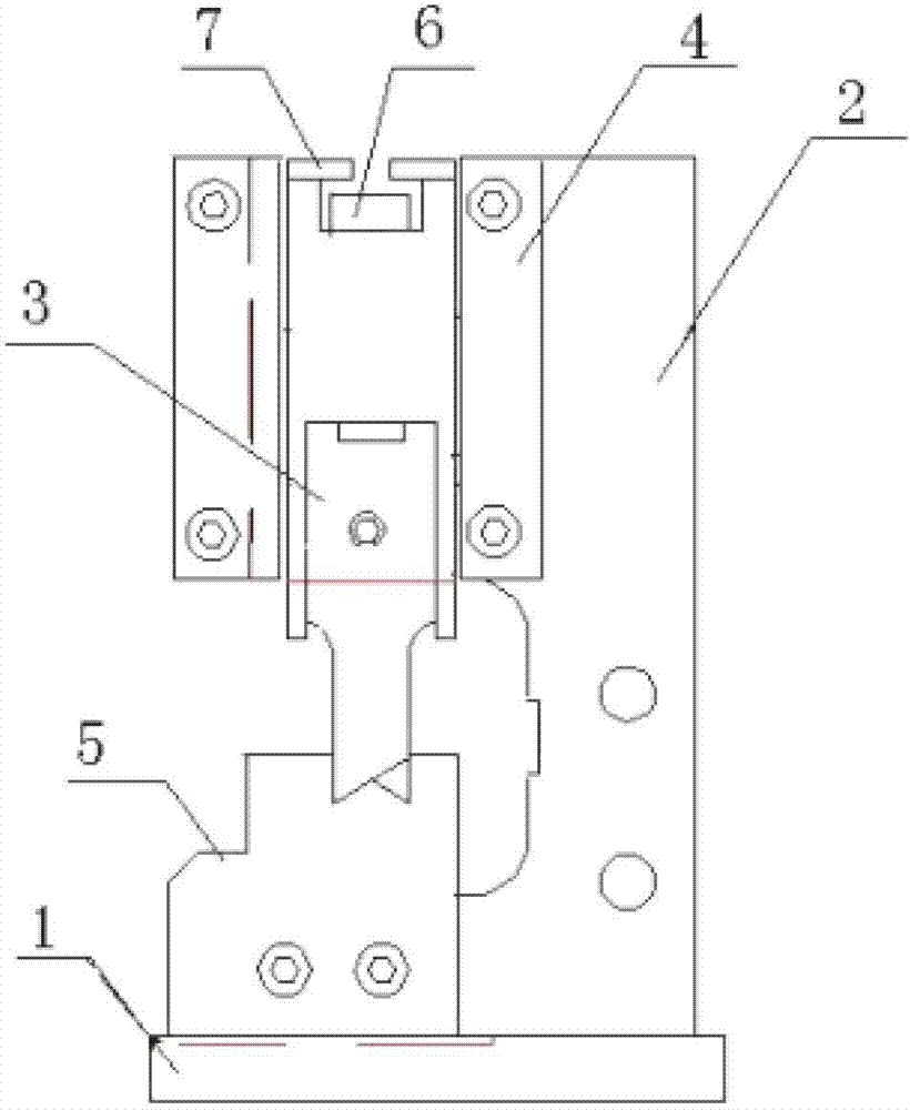
Fig. 1 is structural representation of the present utility model
Fig. 2 is the structural representation of lifting rod in the utility model
Fig. 3 is the structural representation of upper crimping module in the utility model
Embodiment
Now by reference to the accompanying drawings and specific embodiment, the utility model is described in further detail.These accompanying drawings are the schematic diagram of simplification, basic structure of the present utility model only is described in a schematic way, so it only show the formation relevant with the utility model.
Such as Fig. 1,2, shown in 3, a kind of terminal crimping mold, have base 1 and lifting rod 8, die main body 2 is installed on the base 1, die main body 2 tops have slideway, crimping module 3 is installed in the slideway, upper crimping module 3 both sides are provided with slideway fixture 4 on the die main body 2, base 1 is provided with corresponding with upper crimping module 3 connection module 5 that presses down, in upper crimping module 3 upper cavity 31 elastomer 6 is installed, upper crimping module 3 tops are connected with fixed head 7, have a U-shaped hole 71 on the fixed head 7, the U-shaped hole 71 that an end of lifting rod 8 passes fixed head 7 contacts with elastomer 6, and the end of lifting rod 8 these ends has circular protrusions 81, described circular protrusions 81 diameters are greater than the diameter in U-shaped hole 71, and the other end of lifting rod 8 links to each other with expansion link on the crimping apparatus.
The operation principle of the utility model terminal crimping mold is: after being installed to die main body 2 on the terminal crimping apparatus, by lifting rod 8 connecting molds and equipment, equipment provides thrust to lifting rod 8, promoting lifting rod 8 moves downward, the upper crimping module of lifting rod 8 compression elasticity bodies and then promotion moves downward, with the tubular terminal of 0.1-10 square of arbitrary specification as for pressing down on the connection module 5, when upper crimping module 3 with press down connection module 5 when closed, the thrust that lifting rod 8 produces is delivered on the tubular terminal through upper crimping module 3, again to pressing down connection module, fix because pressing down connection module 5, above pressure welding mold piece 3 continues to move downward, thereby make crimping module 3 and press down the be under pressure distortion and compressing of terminal between the connection module 5, when the crimp force that bears when terminal reaches a peak, the active force that upper crimping module 3 continues to move downward changes elastomeric deformation quantity into, thereby make downforce reach an equivalent, terminal compression joint is finished, upper crimping module 3 with press down connection module 5 and separate, upper crimping module 3 is returned to initial position, the next circulation of beginning.
This mould can be realized a tractor serves several purposes, can crimping 0.1-10 square of all kinds of tubular terminals, once adjust, need not again to regulate during the tubular terminal of crimping different model, greatly improved working (machining) efficiency; Adopted polyurethane elastomer to reset, deformation quantity is high, can adapt to the crimping of multiple wire rod.

Claims (3)

1.一种端子压接模具,其特征在于:具有底座和提拉杆,底座上安装有模具主体,模具主体上部开有滑道,滑道内安装有上压接模块,底座上设有与上压接模块对应的下压接模块,上压接模块上部空腔内安装有弹性体,上压接模块顶部连接有固定板,固定板上开有一个U形孔,提拉杆的一端穿过固定板的U形孔与弹性体接触,且提拉杆这一端的端部具有圆形凸起,所述圆形凸起直径大于U形孔的直径,提拉杆的另一端与压接设备上的伸缩杆相连。1. A terminal crimping mold, characterized in that: it has a base and a lifting rod, a mold main body is installed on the base, a slideway is opened on the upper part of the mold main body, an upper crimping module is installed in the slideway, and an upper pressing module is installed on the base. The lower crimping module corresponding to the connection module, the upper cavity of the upper crimping module is installed with an elastic body, the top of the upper crimping module is connected with a fixing plate, and a U-shaped hole is opened on the fixing plate, and one end of the lifting rod passes through the fixing plate The U-shaped hole of the U-shaped hole is in contact with the elastic body, and the end of this end of the lifting rod has a circular protrusion, and the diameter of the circular protrusion is larger than the diameter of the U-shaped hole. connected. 2.根据权利要求1所述的端子压接模具,其特征在于:所述的模具主体上上压接模块两侧设有滑道固定件。2 . The terminal crimping die according to claim 1 , characterized in that slideway fixing pieces are arranged on both sides of the upper crimping module on the mold body. 3 . 3.根据权利要求1所述的端子压接模具,其特征在于:所述的弹性体为圆柱形的聚氨酯弹性体。3. The terminal crimping die according to claim 1, wherein the elastic body is a cylindrical polyurethane elastic body.
CN201220315282.0U 2012-06-29 2012-06-29 Terminal crimping die Withdrawn - After Issue CN202662960U (en)

Priority Applications (1)

Application Number Priority Date Filing Date Title
CN201220315282.0U CN202662960U (en) 2012-06-29 2012-06-29 Terminal crimping die

Applications Claiming Priority (1)

Application Number Priority Date Filing Date Title
CN201220315282.0U CN202662960U (en) 2012-06-29 2012-06-29 Terminal crimping die

Publications (1)

Publication Number Publication Date
CN202662960U true CN202662960U (en) 2013-01-09

Family

ID=47457839

Family Applications (1)

Application Number Title Priority Date Filing Date
CN201220315282.0U Withdrawn - After Issue CN202662960U (en) 2012-06-29 2012-06-29 Terminal crimping die

Country Status (1)

Country Link
CN (1) CN202662960U (en)

Cited By (3)

* Cited by examiner, † Cited by third party
Publication number Priority date Publication date Assignee Title
CN102801077A (en) * 2012-06-29 2012-11-28 上海和旭电子科技有限公司 Self-adaptive terminal crimping mold
WO2014183307A1 (en) * 2013-05-15 2014-11-20 Zhao Wei End stamping mechanism
CN105125168A (en) * 2015-07-27 2015-12-09 邵燕 Ophthalmological preoperative analysis device

Cited By (4)

* Cited by examiner, † Cited by third party
Publication number Priority date Publication date Assignee Title
CN102801077A (en) * 2012-06-29 2012-11-28 上海和旭电子科技有限公司 Self-adaptive terminal crimping mold
CN102801077B (en) * 2012-06-29 2014-10-08 上海和旭电子科技有限公司 Self-adaptive terminal crimping mold
WO2014183307A1 (en) * 2013-05-15 2014-11-20 Zhao Wei End stamping mechanism
CN105125168A (en) * 2015-07-27 2015-12-09 邵燕 Ophthalmological preoperative analysis device

Similar Documents

Publication Publication Date Title
CN203331442U (en) Novel powder compacting device
CN202586057U (en) Split-type crimping machine
CN103962769B (en) A kind of elastic hold-down mechanism being applied to photovoltaic cell string welding
CN201884844U (en) Compression device of straight pipe joint
CN102801077B (en) Self-adaptive terminal crimping mold
CN203304340U (en) Strain clamp hydraulic shaping device
CN204441014U (en) A kind of double attaching type composite insulator compression bonding apparatus
CN102126196B (en) Hydraulic oil pipe straight connector clamping device and clamping method thereof
CN202291207U (en) Riveting machine for clamping shell of transformer
CN203994822U (en) A kind of low degree of eccentricity propellant spiral shell molding die
CN204183817U (en) A kind of Novel injection mold
CN211888774U (en) Bending device is used in connector production
CN201966474U (en) Hydraulic crimping machine for cable terminals
CN202307709U (en) Relay contact riveting device
CN201072705Y (en) Press mounting mold for transformer coil
CN206677418U (en) A kind of high-performance cold welding machine
CN205056826U (en) Novel mould of suppression head
CN209608072U (en) A kind of automotive wire bundle terminal crimping mold
CN201881123U (en) Elbow connector pressing device for hydraulic oil pipes
CN207655835U (en) Rivet Forming Mechanism
CN216095753U (en) Hydraulic pipe bending machine
CN203994688U (en) A kind of guy structure fixture for wire forming
CN102091925B (en) Hydraulic oil pipe elbow adaptor compression device and compression method thereof
CN201656411U (en) Pressure welding type high-tension metal reel pipe
CN203599823U (en) Motor brake pad press-fit device

Legal Events

Date Code Title Description
C14 Grant of patent or utility model
GR01 Patent grant
AV01 Patent right actively abandoned

Granted publication date: 20130109

Effective date of abandoning: 20141008

AV01 Patent right actively abandoned

Granted publication date: 20130109

Effective date of abandoning: 20141008

RGAV Abandon patent right to avoid regrant