CN202651833U - A New Type of Portable Charger - Google Patents
A New Type of Portable Charger Download PDFInfo
- Publication number
- CN202651833U CN202651833U CN201220246123.XU CN201220246123U CN202651833U CN 202651833 U CN202651833 U CN 202651833U CN 201220246123 U CN201220246123 U CN 201220246123U CN 202651833 U CN202651833 U CN 202651833U
- Authority
- CN
- China
- Prior art keywords
- switch
- cover
- charger
- main control
- usb interface
- Prior art date
- Legal status (The legal status is an assumption and is not a legal conclusion. Google has not performed a legal analysis and makes no representation as to the accuracy of the status listed.)
- Expired - Fee Related
Links
- WHXSMMKQMYFTQS-UHFFFAOYSA-N Lithium Chemical compound [Li] WHXSMMKQMYFTQS-UHFFFAOYSA-N 0.000 claims abstract description 16
- 229910052744 lithium Inorganic materials 0.000 claims abstract description 16
- 238000006243 chemical reaction Methods 0.000 claims abstract description 7
- 239000000428 dust Substances 0.000 claims description 16
- 238000010586 diagram Methods 0.000 description 6
- 238000004880 explosion Methods 0.000 description 3
- 230000000694 effects Effects 0.000 description 2
- 238000000034 method Methods 0.000 description 2
- 230000009286 beneficial effect Effects 0.000 description 1
- 238000005516 engineering process Methods 0.000 description 1
- 229920001690 polydopamine Polymers 0.000 description 1
- 230000002265 prevention Effects 0.000 description 1
- 230000009466 transformation Effects 0.000 description 1
- 238000000844 transformation Methods 0.000 description 1
- 239000002699 waste material Substances 0.000 description 1
Images


Classifications
-
- Y—GENERAL TAGGING OF NEW TECHNOLOGICAL DEVELOPMENTS; GENERAL TAGGING OF CROSS-SECTIONAL TECHNOLOGIES SPANNING OVER SEVERAL SECTIONS OF THE IPC; TECHNICAL SUBJECTS COVERED BY FORMER USPC CROSS-REFERENCE ART COLLECTIONS [XRACs] AND DIGESTS
- Y02—TECHNOLOGIES OR APPLICATIONS FOR MITIGATION OR ADAPTATION AGAINST CLIMATE CHANGE
- Y02E—REDUCTION OF GREENHOUSE GAS [GHG] EMISSIONS, RELATED TO ENERGY GENERATION, TRANSMISSION OR DISTRIBUTION
- Y02E60/00—Enabling technologies; Technologies with a potential or indirect contribution to GHG emissions mitigation
- Y02E60/10—Energy storage using batteries
Landscapes
- Charge And Discharge Circuits For Batteries Or The Like (AREA)
Abstract
本实用新型公开了一种便携式充电器,特别是用3.7V锂电池作为电源,输出为5.2V左右的USB规格充电器,包括外壳,外壳内安装有电路板,电路板上设有USB接口,外壳的一端开设有与USB接口接线端相配合的开口,外壳上还安装有包括主动开关和从动开关的转换部件,从动开关与电路板上的主控电路可开合式连接,不使用充电器时,从动开关断开,主控电路关断,使内部电池基本处于零损耗状态,最大限度的达到节能目的。只有当使用者使用充电器时,施加作用于主动开关,主动开关驱动从动开关闭合,主控电路才被接通而消耗电池能量,同时本实用新型不仅能够最大限度的节约电能,还具备防尘的功能,因此具备良好的应用前景。
The utility model discloses a portable charger, in particular, a USB charger with an output of about 5.2V using a 3.7V lithium battery as a power source, comprising a shell, a circuit board installed in the shell, a USB interface on the circuit board, an opening matching with the USB interface terminal at one end of the shell, a conversion component including an active switch and a slave switch installed on the shell, the slave switch and the main control circuit on the circuit board can be connected in an open-close manner, when the charger is not used, the slave switch is disconnected, the main control circuit is turned off, so that the internal battery is basically in a zero-loss state, and the energy saving purpose is achieved to the maximum extent. Only when the user uses the charger, the active switch is applied, the active switch drives the slave switch to close, and the main control circuit is connected to consume the battery energy. At the same time, the utility model can not only save electric energy to the maximum extent, but also has the function of dustproof, so it has a good application prospect.
Description
技术领域 technical field
本实用新型涉及充电器技术领域,特别是涉及一种新型便携式充电器。 The utility model relates to the technical field of chargers, in particular to a novel portable charger.
背景技术 Background technique
随着社会经济的发展和科学技术水平的不断提高,诸如移动电话、PDA、MP4、iphone等数码产品已经越来越广泛地出现在人们的生活当中,这些数码产品通常都设置有提供工作电源的可充电电池,现有的大多数充电装置为固定式充电器,通过将市电转换为直流电后给数码产品充电,但是在很多情况下通过这种方式充电很不方便,例如在野外或旅行期间找不到充电插座的地方,因而需要一种小型或便携式的充电器,目前市面上也的确出现了一些小型化的充电器,特别是用3.7V锂电池作为电源,输出为5.2V左右的USB规格的充电器,由于充电器电池电压与输出电压的不一致,都必需经过升压才能达到输出规格的要求,升压过程中必需消耗一定的电能。在待机模式下,其升压线路仍然一直在工作,这样会白白浪费电池的电能,即使没有加上负载,过几天或几个星期后,电池的能量会被慢慢的消耗掉,而当使用者急需要给其他数码产品充电时,因电池的能量不足,又要重新给电池充电,这样对使用者造成很大不便,鉴于上述存在的问题及其缺陷,有必要对现有充电器的设计提出新的改进。 With the development of the social economy and the continuous improvement of the level of science and technology, digital products such as mobile phones, PDAs, MP4s, and iphones have appeared more and more widely in people's lives. Rechargeable batteries, most of the existing charging devices are fixed chargers, which can be used to charge digital products after converting the mains power into DC power, but it is inconvenient to charge in this way in many cases, such as during field trips or travel There is no place for a charging socket, so a small or portable charger is needed. At present, there are indeed some miniaturized chargers on the market, especially the USB with a 3.7V lithium battery as the power supply and an output of about 5.2V. Due to the inconsistency between the battery voltage and the output voltage of the charger, the charger must be boosted to meet the output specification requirements, and a certain amount of electric energy must be consumed during the boosting process. In standby mode, its boost circuit is still working all the time, which will waste the power of the battery. Even if there is no load, the energy of the battery will be consumed slowly after a few days or weeks. When the user urgently needs to charge other digital products, the battery needs to be recharged because of the insufficient energy of the battery, which causes great inconvenience to the user. The design proposes new improvements.
实用新型内容 Utility model content
针对上述问题,本实用新型提供了一种处于待机状态时具备电能零损耗的新型便携式充电器。 In view of the above problems, the utility model provides a novel portable charger with zero loss of electric energy when it is in a standby state.
本实用新型为解决其技术问题所采用的技术方案是: The technical scheme that the utility model adopts for solving its technical problem is:
一种新型便携式充电器,包括外壳,所述外壳内安装有电路板,所述电路板上设有USB接口,外壳的一端开设有与USB接口接线端相配合的开口,其特征在于:所述外壳上还安装有一转换部件,所述转换部件包括主动开关和由主动开关驱动的从动开关,所述从动开关与电路板上的主控电路可开合式连接,不使用充电器时,从动开关断开,主控电路关断,使用充电器时,施加作用力于主动开关,主动开关驱动从动开关闭合,主控电路接通。 A new type of portable charger, comprising a casing, a circuit board is installed in the casing, a USB interface is provided on the circuit board, and an opening matching with a terminal of the USB interface is provided at one end of the casing, and the characteristics are as follows: There is also a conversion part installed on the shell, and the conversion part includes an active switch and a slave switch driven by the active switch. The slave switch can be opened and closed connected with the main control circuit on the circuit board. When the active switch is disconnected, the main control circuit is turned off. When the charger is used, an active force is applied to the active switch. The active switch drives the slave switch to close, and the main control circuit is connected.
作为对上述方案的进一步改进,所述主动开关包括一防尘盖,所述防尘盖滑动式安装在外壳的一端,一驱动连接件,所述驱动连接件设置于防尘盖底部,驱动连接件上设有第一斜面,一复位部件,所述复位部件一端与驱动连接件连接,另一端与外壳内壁相连,用于防尘盖的复位,不使用充电器时,防尘盖遮住开口,USB接口接线端内置,使用充电器时,防尘盖滑动开启,USB接口接线端外露。 As a further improvement to the above solution, the active switch includes a dust cover, the dust cover is slidably installed at one end of the casing, and a drive connector, the drive connector is arranged at the bottom of the dust cover, and the drive connection The part is provided with a first inclined plane and a reset part. One end of the reset part is connected with the driving connector, and the other end is connected with the inner wall of the housing, which is used for resetting the dust-proof cover. When the charger is not in use, the dust-proof cover covers the opening. , The USB interface terminal is built-in. When using the charger, the dust cover slides open, and the USB interface terminal is exposed.
进一步,所述从动开关包括底座,底座上设有与第一斜面相配合的第二斜面,所述第二斜面活动式安装在底座上。 Further, the driven switch includes a base, on which a second slope matching the first slope is provided, and the second slope is movably mounted on the base.
进一步,所述外壳的一端设有端盖,所述开口开设于该端盖上,端盖上设有滑槽,所述防尘盖设置于端盖一侧,防尘盖底部设有滑杆,所述滑杆穿过滑槽后与端盖另一侧的驱动连接件相连。 Further, one end of the shell is provided with an end cover, the opening is opened on the end cover, a slide groove is provided on the end cover, the dust cover is arranged on one side of the end cover, and a slide bar is provided at the bottom of the dust cover , after passing through the chute, the sliding rod is connected with the driving connector on the other side of the end cover.
进一步,所述端盖上开设有挂孔,所述挂孔上安装有挂扣。 Further, a hanging hole is opened on the end cover, and a hanging buckle is installed on the hanging hole.
此外,所述主控电路包括输入端、充电状态控制模块、灯光控制模块、锂电池以及升压模块,输入端一端接充电状态控制模块,另一端接地,充电状态控制模块和灯光控制模块分别与锂电池正极相连,锂电池负极接地,升压模块的输入端连接锂电池正极,其输出端与USB接口相连,所述从动开关设置于锂电池正极与升压模块的输入端之间。 In addition, the main control circuit includes an input terminal, a charging state control module, a lighting control module, a lithium battery and a booster module. One end of the input terminal is connected to the charging state control module, and the other end is grounded. The positive pole of the lithium battery is connected, the negative pole of the lithium battery is grounded, the input terminal of the boost module is connected to the positive pole of the lithium battery, and the output terminal is connected to the USB interface. The driven switch is arranged between the positive pole of the lithium battery and the input terminal of the boost module.
本实用新型的有益效果是:本实用新型作为一种新型便携式充电器,主要包括主动开关和由主动开关驱动的从动开关,从动开关与电路板上的主控电路可开合式连接,主动开关包括防尘盖,所述防尘盖安装于端盖的一侧,当使用者使用需要使用充电器时,推开防尘盖,此时USB接口外露,可以与外部的数码产品通过带USB插头的连接线进行连接,同时使充电器内部的从动开关进行同步切换,从动开关接通内部升压模块线路,电路处于充电工作状态,使用完毕后,当使用者抽出数码产品的连接线时,防尘盖自动弹回,并同时驱动从动开关断开,内部升压电路关断不工作,不会消耗电池能量,达到零损耗的效果,即只有当使用者每次插上USB插头线给数码产品充电时,才会消耗电池能量。同时本实用新型不仅能够最大限度的节约电能,还具备防尘的功能,因此具备良好的应用前景。 The beneficial effects of the utility model are: the utility model is a new type of portable charger, which mainly includes an active switch and a slave switch driven by the active switch, the slave switch and the main control circuit on the circuit board can be opened and closed, and the active The switch includes a dust-proof cover, which is installed on one side of the end cover. When the user needs to use the charger, the dust-proof cover is pushed away. At this time, the USB interface is exposed, and it can be connected with external digital products through a USB port. The connecting wire of the plug is connected, and the slave switch inside the charger is switched synchronously. The slave switch is connected to the internal boost module circuit, and the circuit is in the charging working state. After use, when the user pulls out the connecting wire of the digital product At this time, the dust cover will automatically spring back, and at the same time drive the driven switch to disconnect, the internal boost circuit will not work, will not consume battery energy, and achieve the effect of zero loss, that is, only when the user plugs in the USB plug each time Battery energy will be consumed only when the cable is used to charge digital products. Simultaneously, the utility model not only can save electric energy to the greatest extent, but also has the function of dust prevention, so it has a good application prospect.
附图说明 Description of drawings
下面结合附图和实施例对本实用新型作进一步说明: Below in conjunction with accompanying drawing and embodiment the utility model is further described:
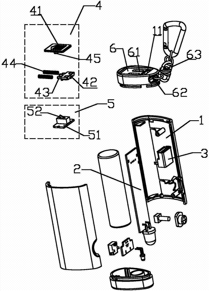
图1为本实用新型爆炸结构示意图; Fig. 1 is a schematic diagram of the explosion structure of the utility model;
图2为本实用新型局部爆炸结构示意图一; Fig. 2 is a schematic diagram of a local explosion structure of the utility model;
图3为本实用新型局部爆炸结构示意图二; Fig. 3 is the second schematic diagram of the local explosion structure of the utility model;
图4为本实用新型所述防尘盖处于滑动开启状态,即主控电路接通时的整体结构示意图; Fig. 4 is a schematic diagram of the overall structure when the dustproof cover of the present invention is in a sliding open state, that is, when the main control circuit is turned on;
图5为本实用新型所述防尘盖处于关闭状态,即主控电路关断时的整体结构示意图; Fig. 5 is a schematic diagram of the overall structure when the dustproof cover of the present invention is in a closed state, that is, when the main control circuit is turned off;
图6为本实用新型所述主控电路原理结构示意图。 FIG. 6 is a schematic structural diagram of the main control circuit of the present invention.
具体实施方式 Detailed ways
参照图1-图6,一种新型便携式充电器,包括外壳1,所述外壳1内安装有电路板2,所述电路板2上设有USB接口3,外壳1的一端开设有与USB接口3接线端相配合的开口11,所述外壳1上还安装有一转换部件,所述转换部件包括主动开关4和由主动开关4驱动的从动开关5,所述从动开关5与电路板2上的主控电路可开合式连接,不使用充电器时,从动开关5断开,主控电路关断,使用充电器时,施加作用力于主动开关4,主动开关4驱动从动开关5闭合,主控电路接通,主动开关4包括一防尘盖41,所述防尘盖41滑动式安装在外壳1的一端,一驱动连接件42,所述驱动连接件42设置于防尘盖41底部,驱动连接件42上设有第一斜面43,一复位部件44,所述复位部件44一端与驱动连接件42连接,另一端与外壳1内壁相连,用于防尘盖41的复位,不使用充电器时,防尘盖41遮住开口11,USB接口3接线端内置,使用充电器时,防尘盖41滑动开启,USB接口3接线端外露,当使用者需要使用充电器时,推开防尘盖41,此时USB接口3外露,可以通过带USB插头的连接线与外部的数码产品进行连接,同时电路内部的从动开关5进行同步切换,从动开关5接通电路,电路处于充电工作状态,使用完毕后,抽出数码产品的连接线,防尘盖41自动弹回,并同时驱动从动开关5断开,内部升压电路被迫关断不工作,达到零损耗的效果。
Referring to Figures 1-6, a new type of portable charger includes a
从动开关5包括底座51,底座51上设有与第一斜面43相配合的第二斜面52,所述第二斜面52活动式安装在底座51上,第二斜面52可绕斜面在底座51的一底角做上下旋转,不使用充电器时,第二斜面52向上弹开,即从动开关5断开,主控电路关断,使用充电器时,滑动防尘盖41,同时带动第一斜面43滑动,第一斜面43使得第二斜面52绕其底角向下旋转,驱动从动开关5闭合,主控电路接通。
The driven
外壳1的一端设有端盖6,所述开口11开设于该端盖6上,端盖6上设有滑槽61,所述防尘盖41设置于端盖6一侧,防尘盖41底部设有滑杆45,所述滑杆45穿过滑槽61后与端盖6另一侧的驱动连接件42相连。
One end of the
端盖6上开设有挂孔62,所述挂孔62上安装有挂扣63,所述挂扣63使得本充电器更便于携带。
A
主控电路包括输入端71、充电状态控制模块72、灯光控制模块73、锂电池74以及升压模块75,输入端71一端接充电状态控制模块72,另一端接地,充电状态控制模块72和灯光控制模块73分别与锂电池74正极相连,锂电池74负极接地,升压模块75的输入端连接锂电池74正极,其输出端与USB接口3相连,所述从动开关5设置于锂电池74正极与升压模块75的输入端之间。
The main control circuit includes an input terminal 71, a charge
以上对本实用新型的较佳实施进行了具体说明,当然,本实用新型还可以采用与上述实施方式不同的形式,这些都不构成对本实施方式的任何限制,熟悉本领域的技术人员在不违背本实用新型精神的前提下所作的等同的变换或相应的改动,都应该属于本实用新型的保护范围内。 The preferred implementation of the present utility model has been specifically described above. Of course, the present utility model can also adopt forms different from the above-mentioned embodiments, and these do not constitute any limitation to the present embodiment. The equivalent transformations or corresponding changes made under the premise of the spirit of the utility model should all fall within the protection scope of the utility model.
Claims (6)
Priority Applications (1)
| Application Number | Priority Date | Filing Date | Title |
|---|---|---|---|
| CN201220246123.XU CN202651833U (en) | 2012-05-29 | 2012-05-29 | A New Type of Portable Charger |
Applications Claiming Priority (1)
| Application Number | Priority Date | Filing Date | Title |
|---|---|---|---|
| CN201220246123.XU CN202651833U (en) | 2012-05-29 | 2012-05-29 | A New Type of Portable Charger |
Publications (1)
| Publication Number | Publication Date |
|---|---|
| CN202651833U true CN202651833U (en) | 2013-01-02 |
Family
ID=47420877
Family Applications (1)
| Application Number | Title | Priority Date | Filing Date |
|---|---|---|---|
| CN201220246123.XU Expired - Fee Related CN202651833U (en) | 2012-05-29 | 2012-05-29 | A New Type of Portable Charger |
Country Status (1)
| Country | Link |
|---|---|
| CN (1) | CN202651833U (en) |
Cited By (4)
| Publication number | Priority date | Publication date | Assignee | Title |
|---|---|---|---|---|
| CN104682505A (en) * | 2015-02-15 | 2015-06-03 | 庄景阳 | Protection device for controlling angle shifting power interruption by virtue of rolling balls during charging of mobile phone |
| WO2017113682A1 (en) * | 2015-12-31 | 2017-07-06 | 乐视控股(北京)有限公司 | Mobile phone charger |
| CN110350623A (en) * | 2019-07-20 | 2019-10-18 | 安徽省聚科石墨烯科技股份公司 | A kind of box body contains the mobile charging device of graphene |
| US11637436B2 (en) * | 2019-10-09 | 2023-04-25 | Jiasheng Wu | Automobile jumpstart adapter for an external battery |
-
2012
- 2012-05-29 CN CN201220246123.XU patent/CN202651833U/en not_active Expired - Fee Related
Cited By (6)
| Publication number | Priority date | Publication date | Assignee | Title |
|---|---|---|---|---|
| CN104682505A (en) * | 2015-02-15 | 2015-06-03 | 庄景阳 | Protection device for controlling angle shifting power interruption by virtue of rolling balls during charging of mobile phone |
| WO2017113682A1 (en) * | 2015-12-31 | 2017-07-06 | 乐视控股(北京)有限公司 | Mobile phone charger |
| CN110350623A (en) * | 2019-07-20 | 2019-10-18 | 安徽省聚科石墨烯科技股份公司 | A kind of box body contains the mobile charging device of graphene |
| US11637436B2 (en) * | 2019-10-09 | 2023-04-25 | Jiasheng Wu | Automobile jumpstart adapter for an external battery |
| US20230179006A1 (en) * | 2019-10-09 | 2023-06-08 | Jiasheng Wu | Automobile jumpstart adapter for an external battery |
| US12132338B2 (en) * | 2019-10-09 | 2024-10-29 | Dopollo Innovations, Inc. | Automobile jumpstart adapter for an external battery |
Similar Documents
| Publication | Publication Date | Title |
|---|---|---|
| US20140266007A1 (en) | Portable Charger | |
| CN204908346U (en) | Handbag that can wirelessly charge | |
| CN205122913U (en) | Multi -functional intelligent movement arranges and inserts | |
| CN202474947U (en) | Portable movable power supply | |
| CN2842842Y (en) | Accumulation energy type mobile charging adapter | |
| CN201112506Y (en) | Universal mobile phone charger | |
| CN201797359U (en) | Portable mobile charging device | |
| CN204679914U (en) | A kind of electronic notebook | |
| CN205092810U (en) | Solar mobile power supply system | |
| CN204578581U (en) | A kind of chargeable mobile phone shell | |
| CN204257957U (en) | A kind of Mobile phone charging socket | |
| CN202586434U (en) | Mobile power supply with Apple mobile phone protective casing | |
| CN203243085U (en) | Multifunctional mobile power supply | |
| CN203039396U (en) | AC and DC combined charger | |
| CN201075857Y (en) | Sheath with solar energy charger unit | |
| CN201556957U (en) | Light energy charger | |
| CN203039377U (en) | Multifunctional universal charger | |
| CN202205134U (en) | Plate computer | |
| CN205960706U (en) | Mobile power supply for charging Bluetooth headset | |
| CN202772641U (en) | Mobile phone charger | |
| CN203312594U (en) | Multifunction wall power socket | |
| CN205610527U (en) | Collapsible intelligent solar energy environmental protection portable power source | |
| CN202373998U (en) | Charger and charging equipment comprising charger | |
| CN204205688U (en) | A kind of charger with switch | |
| CN221380580U (en) | Portable charger |
Legal Events
| Date | Code | Title | Description |
|---|---|---|---|
| C14 | Grant of patent or utility model | ||
| GR01 | Patent grant | ||
| CF01 | Termination of patent right due to non-payment of annual fee |
Granted publication date: 20130102 Termination date: 20150529 |
|
| EXPY | Termination of patent right or utility model |