CN202642998U - Portable tightening coil holder - Google Patents
Portable tightening coil holder Download PDFInfo
- Publication number
- CN202642998U CN202642998U CN 201220216911 CN201220216911U CN202642998U CN 202642998 U CN202642998 U CN 202642998U CN 201220216911 CN201220216911 CN 201220216911 CN 201220216911 U CN201220216911 U CN 201220216911U CN 202642998 U CN202642998 U CN 202642998U
- Authority
- CN
- China
- Prior art keywords
- movable column
- plate
- upper plate
- welded
- clamping device
- Prior art date
- Legal status (The legal status is an assumption and is not a legal conclusion. Google has not performed a legal analysis and makes no representation as to the accuracy of the status listed.)
- Expired - Fee Related
Links
Images

Landscapes
- Reciprocating, Oscillating Or Vibrating Motors (AREA)
Abstract
本实用新型公开了一种便携式收紧线架,包括上盘、下盘、中心轴、活动柱,所述中心轴焊接固定在下盘的中心,活动柱沿圆周活动安装在下盘上,中心轴的上端焊接一与中心轴垂直的平板,平板上设置螺栓孔,上盘的中间位置设置与平板的螺栓孔对应的螺纹孔,上盘的圆周固定设置与活动柱对应的卡紧装置。所述活动柱的下端设置两个与活动柱垂直的端柱,下盘上焊接两个相对设置的套装端柱的套环。本实用新型具有结构简单、美观实用、成本低廉、便于携带的优点。
The utility model discloses a portable tightening wire rack, which comprises an upper plate, a lower plate, a central shaft and a movable column. The upper end is welded with a flat plate perpendicular to the central axis. Bolt holes are set on the flat plate. Threaded holes corresponding to the bolt holes of the flat plate are set in the middle of the upper plate. The circumference of the upper plate is fixed with a clamping device corresponding to the movable column. The lower end of the movable column is provided with two end columns perpendicular to the movable column, and the lower plate is welded with two opposite collars for fitting the end columns. The utility model has the advantages of simple structure, beautiful and practical, low cost and easy to carry.
Description
技术领域 technical field
本实用新型涉及一种电力线路中整理导线的工具,具体的说是一种对导线进行回收和整理的便携式收紧线架。 The utility model relates to a tool for arranging wires in power lines, in particular to a portable tightening wire rack for recycling and arranging the wires.
背景技术 Background technique
电力系统不断发展,有的电力线路会要升高电压等级和扩容,这样,电力线路的导线回收成为经常要做的工作。为了节省人力、提高效率,电力部门通常借助专用的收紧线车进行导线回收和整理的工作。然而,在线路施工中,很多时候往往由于场地限制,专用收紧线车体积大,无法进入指定位置。 With the continuous development of the power system, some power lines will have to increase the voltage level and expand the capacity. In this way, the recovery of the wires of the power lines has become a frequent work. In order to save manpower and improve efficiency, the electric power department usually uses a special tightening wire car to recycle and organize the wires. However, in line construction, often due to site constraints, the special tightening line car is bulky and cannot enter the designated position. the
实用新型内容 Utility model content
本实用新型需要解决的技术问题是提供一种不受场地限制的便携式收紧线架。 The technical problem to be solved by the utility model is to provide a portable tightening wire frame which is not limited by the site.
为解决上述技术问题,本实用新型所采用的技术方案是: In order to solve the problems of the technologies described above, the technical solution adopted in the utility model is:
便携式收紧线架,包括上盘、下盘、中心轴、活动柱,所述中心轴焊接固定在下盘的中心,活动柱沿圆周活动安装在下盘上,中心轴的上端焊接一与中心轴垂直的平板,平板上设置螺栓孔,上盘的中间位置设置与平板的螺栓孔对应的螺纹孔,上盘的圆周固定设置与活动柱对应的卡紧装置。 Portable tightening frame, including upper plate, lower plate, central shaft, movable column, the central axis is welded and fixed in the center of the lower plate, the movable column is installed on the lower plate along the circumference, and the upper end of the central axis is welded to be perpendicular to the central axis Bolt holes are set on the plate, threaded holes corresponding to the bolt holes of the plate are set in the middle of the upper plate, and the circumference of the upper plate is fixedly provided with a clamping device corresponding to the movable column.
本实用新型的进一步改进在于:所述活动柱的下端设置两个与活动柱垂直的端柱,下盘上焊接两个相对设置的套装端柱的套环。 The further improvement of the utility model lies in that: the lower end of the movable column is provided with two end columns perpendicular to the movable column, and the lower plate is welded with two oppositely arranged collars for fitting the end columns.
本实用新型的进一步改进在于:所述活动柱为带有中心孔的圆筒结构,上盘的卡紧装置为与活动柱的中心孔配合的卡柱。 The further improvement of the utility model is that: the movable column is a cylindrical structure with a central hole, and the clamping device of the upper plate is a clamping column matched with the central hole of the movable column.
本实用新型的进一步改进在于:所述活动柱为圆柱结构,上盘的卡紧装置为套装活动柱的卡套。 The further improvement of the utility model is that: the movable column is a cylindrical structure, and the clamping device of the upper plate is a ferrule for fitting the movable column.
由于采用了上述技术方案,本实用新型取得的技术进步是: Owing to having adopted above-mentioned technical scheme, the technical progress that the utility model obtains is:
本实用新型在使用时,中心轴通过平板上的螺栓与上盘固定,活动柱通过与之配合的卡紧装置与上盘固定。本实用新型可方便安装在小型拖拉机后轮上,利用差速工作,由拖拉机的变速箱和油门控制收紧线速度,即可减少新导线的损失长度,又可以将旧导线方便收线同时盘绕成轴以便再利用。当收线成盘以后,可以松开中心轴的平板上的螺栓,使活动柱从卡紧装置中脱出,摘下上盘以后,即可将成盘的导线收纳,随后再次安装好上盘,继续回收导线。本实用新型具有结构简单、美观实用、成本低廉、便于携带的优点。 When the utility model is in use, the central shaft is fixed to the upper plate through bolts on the flat plate, and the movable column is fixed to the upper plate through the clamping device matched therewith. The utility model can be conveniently installed on the rear wheel of a small tractor, works with differential speed, and the speed of tightening is controlled by the gearbox and throttle of the tractor, which can reduce the loss length of new wires, and can conveniently take up the old wires and coil them at the same time Shafted for reuse. After the wire is wound up into a coil, the bolt on the flat plate of the central shaft can be loosened to make the movable column come out of the clamping device. After the upper disc is taken off, the coiled wire can be stored, and then the upper disc can be installed again to continue Recycle the wire. The utility model has the advantages of simple structure, beautiful and practical, low cost and easy to carry.
附图说明 Description of drawings
图1是本实用新型的一种实施例的结构示意图; Fig. 1 is the structural representation of a kind of embodiment of the utility model;
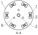
图2是图1的A-A向截面视图。 Fig. 2 is a sectional view taken along line A-A of Fig. 1 .
其中,1、下盘,2、活动柱,3、上盘,4、螺栓,5、卡柱,6、中心轴,7、套环,8、通孔,9、平板。 Wherein, 1, the lower plate, 2, the movable column, 3, the upper plate, 4, the bolt, 5, the clamping column, 6, the central shaft, 7, the collar, 8, the through hole, 9, the flat plate.
具体实施方式 Detailed ways
下面结合附图对本实用新型做进一步详细说明: Below in conjunction with accompanying drawing, the utility model is described in further detail:
便携式收紧线架,如图1、图2所示,包括上盘3、下盘1、中心轴6、活动柱2。所述中心轴6可以为空心的筒状,也可以是实心的柱状。中心轴6的下端焊接固定在下盘1的中心。中心轴6的上端焊接一与中心轴垂直的平板9,平板上开有螺栓孔。平板9抵住上盘3的下表面,上盘3的中间位置设置与平板9的螺栓孔对应的螺纹孔。通过螺栓4可以将中心轴6与上盘3固定连接为一体。活动柱2沿圆周活动安装在下盘1上,所述活动柱2的下端伸出两个与活动柱垂直的端柱,两个端柱与活动柱构成T型结构。在下盘1上焊接两个相对设置的套环7,将端柱套装在套环7里,实现活动柱在与上盘不连接的情况下,可以向中心轴收缩或向周围散开。上盘3的圆周固定设置与活动柱对应的卡紧装置。当所述活动柱2为带有中心孔的圆筒结构时,上盘3的卡紧装置为与活动柱的中心孔配合的卡柱5。
The portable tightening wire stand, as shown in Fig. 1 and Fig. 2, includes an
本实用新型的另一种实施例,所述活动柱2为圆柱结构,上盘3的卡紧装置为套装活动柱的卡套。
In another embodiment of the present utility model, the
Claims (4)
Priority Applications (1)
| Application Number | Priority Date | Filing Date | Title |
|---|---|---|---|
| CN 201220216911 CN202642998U (en) | 2012-05-15 | 2012-05-15 | Portable tightening coil holder |
Applications Claiming Priority (1)
| Application Number | Priority Date | Filing Date | Title |
|---|---|---|---|
| CN 201220216911 CN202642998U (en) | 2012-05-15 | 2012-05-15 | Portable tightening coil holder |
Publications (1)
| Publication Number | Publication Date |
|---|---|
| CN202642998U true CN202642998U (en) | 2013-01-02 |
Family
ID=47412135
Family Applications (1)
| Application Number | Title | Priority Date | Filing Date |
|---|---|---|---|
| CN 201220216911 Expired - Fee Related CN202642998U (en) | 2012-05-15 | 2012-05-15 | Portable tightening coil holder |
Country Status (1)
| Country | Link |
|---|---|
| CN (1) | CN202642998U (en) |
Cited By (6)
| Publication number | Priority date | Publication date | Assignee | Title |
|---|---|---|---|---|
| CN103287927A (en) * | 2013-06-28 | 2013-09-11 | 上海广为电器工具有限公司 | Automatically expandable take-up reel and winding method |
| CN103754694A (en) * | 2014-01-16 | 2014-04-30 | 江苏赛福天钢索股份有限公司 | Take-up device of coiled wire ropes |
| CN105883483A (en) * | 2016-06-11 | 2016-08-24 | 林清金 | Cable take-up equipment |
| CN105905671A (en) * | 2016-06-11 | 2016-08-31 | 林清金 | Cable recycling equipment |
| CN106505480A (en) * | 2016-12-30 | 2017-03-15 | 安徽泰富重工制造有限公司 | A kind of combined wheel disc for communication cable laying |
| CN111515164A (en) * | 2020-04-30 | 2020-08-11 | 张珈铭 | Brush hair reinforcement type automatic mould scavenging machine |
-
2012
- 2012-05-15 CN CN 201220216911 patent/CN202642998U/en not_active Expired - Fee Related
Cited By (7)
| Publication number | Priority date | Publication date | Assignee | Title |
|---|---|---|---|---|
| CN103287927A (en) * | 2013-06-28 | 2013-09-11 | 上海广为电器工具有限公司 | Automatically expandable take-up reel and winding method |
| CN103287927B (en) * | 2013-06-28 | 2015-11-18 | 浙江广为电器工具有限公司 | Automatic harmomegathus take-up pulley dish and method for winding thereof |
| CN103754694A (en) * | 2014-01-16 | 2014-04-30 | 江苏赛福天钢索股份有限公司 | Take-up device of coiled wire ropes |
| CN105883483A (en) * | 2016-06-11 | 2016-08-24 | 林清金 | Cable take-up equipment |
| CN105905671A (en) * | 2016-06-11 | 2016-08-31 | 林清金 | Cable recycling equipment |
| CN106505480A (en) * | 2016-12-30 | 2017-03-15 | 安徽泰富重工制造有限公司 | A kind of combined wheel disc for communication cable laying |
| CN111515164A (en) * | 2020-04-30 | 2020-08-11 | 张珈铭 | Brush hair reinforcement type automatic mould scavenging machine |
Similar Documents
| Publication | Publication Date | Title |
|---|---|---|
| CN103368104A (en) | Insulating operating rod of ground potential operation non-bearing-strength consecutive wire clamp | |
| CN203624957U (en) | Jacking-up device used for roller body | |
| CN203419636U (en) | Cable reel | |
| CN103234817A (en) | Detachable and reusable clamping apparatus for tensile test of fiber-reinforced resin based composite mandril | |
| CN202943589U (en) | Sleeving device of rubber sleeve | |
| CN203356288U (en) | Simple copper pipe bending device | |
| CN203230177U (en) | Tool type column formwork fixing fastener | |
| CN202466999U (en) | Reinforcing steel bar mechanical connecting device | |
| CN202527900U (en) | Recoiling machine sleeve dismounting device | |
| CN205765931U (en) | A kind of metal threading pipe joint attachment means | |
| CN204179244U (en) | Earth electrode formula earth connection integrated device | |
| CN203367879U (en) | Insulating operating rod of earth potential working non-bearing-force connection wire clamp | |
| CN204729449U (en) | Double anti-theft bolt | |
| CN203317289U (en) | Wrench for fastening nut | |
| CN204315297U (en) | A kind of adjustable tension straightening device | |
| CN203143835U (en) | Electric power cable coiling recovery device | |
| CN203536850U (en) | Wire feed device for wire fast die exchanging | |
| CN211219522U (en) | Ground anchor dismantling equipment for power engineering | |
| CN203292899U (en) | Coiled tube end clamping mechanism | |
| CN204897028U (en) | Portable earth connection support | |
| CN206907358U (en) | A fixed bracket structure for an electric warning sign | |
| CN203729914U (en) | Long spiral drilling machine drill stem automatic clamping device | |
| CN202970115U (en) | Rail support embedded under ground | |
| CN203680195U (en) | Universal tool for installing electric transmission line anti-theft cap | |
| CN205346485U (en) | Cable coiler |
Legal Events
| Date | Code | Title | Description |
|---|---|---|---|
| C14 | Grant of patent or utility model | ||
| GR01 | Patent grant | ||
| CF01 | Termination of patent right due to non-payment of annual fee |
Granted publication date: 20130102 Termination date: 20190515 |
|
| CF01 | Termination of patent right due to non-payment of annual fee |