CN202627023U - Slide well lid - Google Patents
Slide well lid Download PDFInfo
- Publication number
- CN202627023U CN202627023U CN 201220184042 CN201220184042U CN202627023U CN 202627023 U CN202627023 U CN 202627023U CN 201220184042 CN201220184042 CN 201220184042 CN 201220184042 U CN201220184042 U CN 201220184042U CN 202627023 U CN202627023 U CN 202627023U
- Authority
- CN
- China
- Prior art keywords
- well lid
- rail wheel
- rail
- track
- push rod
- Prior art date
- Legal status (The legal status is an assumption and is not a legal conclusion. Google has not performed a legal analysis and makes no representation as to the accuracy of the status listed.)
- Expired - Fee Related
Links
- 230000007246 mechanism Effects 0.000 claims abstract description 12
- NJPPVKZQTLUDBO-UHFFFAOYSA-N novaluron Chemical compound C1=C(Cl)C(OC(F)(F)C(OC(F)(F)F)F)=CC=C1NC(=O)NC(=O)C1=C(F)C=CC=C1F NJPPVKZQTLUDBO-UHFFFAOYSA-N 0.000 claims description 17
- 238000012423 maintenance Methods 0.000 abstract description 11
- 229910000831 Steel Inorganic materials 0.000 description 14
- 239000010959 steel Substances 0.000 description 14
- 238000009434 installation Methods 0.000 description 6
- 238000000034 method Methods 0.000 description 4
- 239000000428 dust Substances 0.000 description 3
- 238000004519 manufacturing process Methods 0.000 description 3
- 230000000694 effects Effects 0.000 description 2
- 230000002787 reinforcement Effects 0.000 description 2
- 238000007789 sealing Methods 0.000 description 2
- XEEYBQQBJWHFJM-UHFFFAOYSA-N Iron Chemical group [Fe] XEEYBQQBJWHFJM-UHFFFAOYSA-N 0.000 description 1
- GQWNECFJGBQMBO-UHFFFAOYSA-N Molindone hydrochloride Chemical compound Cl.O=C1C=2C(CC)=C(C)NC=2CCC1CN1CCOCC1 GQWNECFJGBQMBO-UHFFFAOYSA-N 0.000 description 1
- 230000009286 beneficial effect Effects 0.000 description 1
- 239000004568 cement Substances 0.000 description 1
- 230000007812 deficiency Effects 0.000 description 1
- 230000008021 deposition Effects 0.000 description 1
- 238000005516 engineering process Methods 0.000 description 1
- 239000003500 flue dust Substances 0.000 description 1
- 230000002093 peripheral effect Effects 0.000 description 1
- 239000011150 reinforced concrete Substances 0.000 description 1
- 230000003014 reinforcing effect Effects 0.000 description 1
- 238000003466 welding Methods 0.000 description 1
Images


Landscapes
- Underground Structures, Protecting, Testing And Restoring Foundations (AREA)
Abstract
The utility model relates to a slide well lid. The slide well lid is characterized by comprising a well lid, rail wheels, rails and jacking mechanisms. Rails are respectively arranged on the front side and the rear side of a wellhead, the well lid is arranged above the wellhead, four corners of the well lid are respectively provided with the rail wheels which are placed on the rails, and each rail is provided with two rail wheel ports. One jacking mechanism is arranged below each rail wheel port, a protruded board of each jacking mechanism is placed under each rail wheel port, and when the well lid is closed, the four rail wheels respectively fall into the corresponding rail wheel ports. The slide well lid is simple in structure, and convenient and rapid to operate, is provided with the structure capable of being opened and closed smoothly, and brings convenience to ingress and egress of workers during daily maintenance and repair for underground facilities.
Description
Technical field
The utility model relates to a kind of well lid.
Background technology
Production department dust such as every coke-oven plant, cement plant are all more serious, and some mechanical electric equipment all are installed in basement, and for isolated dust atmosphere, the well lid sealing is adopted at the top, access of these underground installations.Well lid adopts steel plate to make usually, is welded with at surface of steel plate and lifts ear, and when regular maintenance and maintenance underground installation, the mode that needs many people to adopt steel pipe to lift could be opened well lid, also can only close with identical method.Therefore, press for a kind of well lid that can be convenient to open and close, to solve the deficiency in the existing operation.
Summary of the invention
The utility model technical problem to be solved is: to the problems referred to above; The purpose of the utility model is to provide a kind of slip well lid simple in structure; Simple operation has the structure of opening and closing smoothly, is convenient to the discrepancy of staff's regular maintenance and maintenance underground installation.
For realizing above-mentioned purpose, the technical scheme that the utility model adopts is that the slip well lid is characterized in that: it comprises well lid, rail wheel, track and lifting body; The both sides, front and back of well head are respectively equipped with track (track is fixed on the basement well lid pedestal); Well lid is positioned at the top of well head, and four bights of well lid are respectively equipped with rail wheel, and rail wheel is positioned on the track; Each track is provided with two rail wheel mouths; Each rail wheel mouth below all is provided with lifting body, the flange of lifting body be positioned at the rail wheel mouth under; When well lid was closed, four rail wheels fell into corresponding rail wheel mouth respectively.
Lifting body comprises push rod, bearing pin, flange and foot-driven lever; Push rod is by bearing pin and basement well lid pedestal hinged (bearing pin is fixed on the side of basement well lid pedestal, and push rod is installed on the bearing pin), and push rod is provided with flange from the nearer end of bearing pin, and the push rod other end is provided with foot-driven lever.
Between two lifting bodies of well head the same side, be provided with locking mechanism.
Locking mechanism comprises backstay, location pole socket; The location pole socket is fixed on the basement well lid pedestal, and backstay is the T type, and the lower end of backstay is hinged on the pole socket of location.
The beneficial effect of the utility model is:
1, simple in structure, simple operation (easy to use).
2, the structure that has opening and closing smoothly is convenient to the discrepancy of staff's regular maintenance and maintenance underground installation.
3, the position that can sink down after closing has effectively completely cut off the flue dust environment.
Description of drawings
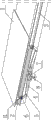
Fig. 1 is the structural representation of the utility model.
Fig. 2 is the sketch map of the utility model locking mechanism.
Sketch map when Fig. 3 closes for the utility model.
Sketch map when Fig. 4 opens for the utility model.
Among the figure: 1. well lid; 2. rail wheel; 3. track; 4. push rod; 5. bearing pin; 6. flange; 7. foot-driven lever; 8. backstay; 9. location pole socket; 10. basement well lid pedestal; 11. rail wheel mouth.
The specific embodiment
In order to understand the utility model better, the technical scheme of the utility model is done further explanation below in conjunction with embodiment and accompanying drawing.
The slip well lid that the utility model provides, its structure is as shown in Figure 1, and it comprises well lid 1, rail wheel 2, track 3, lifting body and locking mechanism, and wherein, lifting body comprises push rod 4, bearing pin 5, flange 6 and foot-driven lever 7, and lifting body is a quadruplet; Locking mechanism comprises backstay 8, location pole socket 9 (shown in Figure 2), and locking mechanism is two covers.The both sides, front and back of well head are respectively equipped with track (track is fixed on the basement well lid pedestal 10); Each track is provided with two rail wheel mouths.Well lid is positioned at the top of well head, and four bights of well lid are respectively equipped with rail wheel, and rail wheel is positioned at (2 rail wheels of the same side are positioned on the same track) on the track.Each rail wheel mouth below all is provided with lifting body, the flange of lifting body be positioned at the rail wheel mouth under; Push rod is by bearing pin and basement well lid pedestal hinged (bearing pin is fixed on the side of basement well lid pedestal, and push rod is installed on the bearing pin), and push rod is provided with flange from the nearer end of bearing pin, and the push rod other end is provided with foot-driven lever.Between two lifting bodies of well head the same side, be provided with locking mechanism; The location pole socket is fixed on the basement well lid pedestal, and backstay is the T type, and the lower end of backstay is hinged on the pole socket of location.When well lid was closed, four rail wheels fell into corresponding rail wheel mouth respectively.
Said well lid 1 adopts steel plate to make, and it is shaped as square, and area is greater than well head, and four angles are rounding, in case hurt sb.'s feelings.
Bearing pin 5 adopts reinforcement fabrication, and an end is embedded on the basement well lid pedestal 10, and the other end has screw thread and nut is installed, so that fixed mandril 4.
Flange is that two-layered steel plates is welded together, below one deck steel plate greater than the rail wheel mouth on the track, above one deck steel plate less than the rail wheel mouth on the track, flange is during by jack-up, above upper surface and the upper surface of rail wheel mouth of one deck steel plate be positioned on the same plane.
Foot-driven lever 7 is located at the end of push rod √ type structure, by a straight-bar and a brace, is connected with the push rod end, forms a triangular facet, so that operating personnel trample.
Backstay 8 adopts reinforcement fabrication, is two reinforcing bar T type welding, and one of straight section is provided with groove and hole, so that be hinged on the pole socket of location.
Location pole socket 9 adopts steel plates to make, and is base plate and otic placode, and base plate is processed into box-shaped and is installed on the basement well lid pedestal 10, and otic placode is processed into rectangle, and one is connected with base plate, and rounding is processed in the other end, and is provided with the hole, so that installing and locating bar 8.
The slip well lid that the utility model provides uses when staff's regular maintenance is come in and gone out basement with the maintenance underground installation.
During use, closing with well lid 1 is original state (shown in Figure 3), and at this moment, rail wheel 2 drops in the rail wheel mouth 11 of track 3, and track 3 does not have load-bearing, and well lid 1 is pressed on the basement well lid pedestal 10.When needing to open, at first operating personnel trample two foot-driven levers 7 of a side simultaneously with pin, and push rod 4 is rotated for the center along bearing pin 5; Two rail wheels 2 of two 6 while of flange jack-up well lid one sides; The upper surface of flange 6 is concordant with track 3, backstay 8 is mentioned again, and hooks two foot-driven levers 7.With two rail wheels 2 of identical method jack-up well lid 1 opposite side, at this moment, well lid 1 has left basement well lid pedestal 10 fully, and load-bearing promotes well lid gently on track 3, just can open the access.When needs are closed the access (shown in Figure 4), unclamp the backstay 8 of both sides earlier, flange 6 is not supported, again the access is closed in well lid 1 reduction, rail wheel 2 slides and drops in the rail wheel mouth 11 of track 3.
Basement well lid pedestal 10 is a reinforced concrete structure, and it is higher than peripheral terrace, in case the rainwater deposition pours into basement; Its side is reserved with embedded iron parts, so that attachment rail 3.
Effect: dust atmosphere is abominable and by the access of well lid sealing; After having adopted the method for the utility model; The discrepancy of staff's regular maintenance and maintenance underground installation is convenient in the opening and closing access smoothly, explains that the method effect of the utility model is remarkable.
More than explanation is merely the application implementation example of the utility model, can not limit the interest field of the utility model certainly with this, therefore changes according to the equivalence that the utility model claim is done, and still belongs to the protection domain of the utility model.
Claims (4)
1. slip well lid, it is characterized in that: it comprises well lid (1), rail wheel (2), track (3) and lifting body; The both sides, front and back of well head are respectively equipped with track (3); Well lid (1) is positioned at the top of well head, and four bights of well lid (1) are respectively equipped with rail wheel (2), and rail wheel (2) is positioned on the track (3); Each track (3) is provided with two rail wheel mouths (11); Each rail wheel mouth (11) below all is provided with lifting body, the flange of lifting body (6) be positioned at rail wheel mouth (11) under; Well lid (1) is when closing, and four rail wheels (2) fall into corresponding rail wheel mouth (11) respectively.
2. slip well lid according to claim 1 is characterized in that: lifting body comprises push rod (4), bearing pin (5), flange (6) and foot-driven lever (7); Push rod (4) is hinged by bearing pin (5) and basement well lid pedestal (10), and push rod (4) is provided with flange (6) from the nearer end of bearing pin (5), and push rod (4) other end is provided with foot-driven lever (7).
3. slip well lid according to claim 1 is characterized in that: between two lifting bodies of well head the same side, be provided with locking mechanism.
4. slip well lid according to claim 3 is characterized in that: locking mechanism comprises backstay (8), location pole socket (9); Location pole socket (9) is fixed on the basement well lid pedestal (10), and backstay (8) is the T type, and the lower end of backstay (8) is hinged on the location pole socket (9).
Priority Applications (1)
| Application Number | Priority Date | Filing Date | Title |
|---|---|---|---|
| CN 201220184042 CN202627023U (en) | 2012-04-27 | 2012-04-27 | Slide well lid |
Applications Claiming Priority (1)
| Application Number | Priority Date | Filing Date | Title |
|---|---|---|---|
| CN 201220184042 CN202627023U (en) | 2012-04-27 | 2012-04-27 | Slide well lid |
Publications (1)
| Publication Number | Publication Date |
|---|---|
| CN202627023U true CN202627023U (en) | 2012-12-26 |
Family
ID=47380234
Family Applications (1)
| Application Number | Title | Priority Date | Filing Date |
|---|---|---|---|
| CN 201220184042 Expired - Fee Related CN202627023U (en) | 2012-04-27 | 2012-04-27 | Slide well lid |
Country Status (1)
| Country | Link |
|---|---|
| CN (1) | CN202627023U (en) |
Cited By (2)
| Publication number | Priority date | Publication date | Assignee | Title |
|---|---|---|---|---|
| CN108755774A (en) * | 2018-07-01 | 2018-11-06 | 吴孔杰 | A kind of cover of water meter chamber for being convenient for making an inventory water meter |
| CN112681385A (en) * | 2020-12-02 | 2021-04-20 | 宜春鸿辉新型建筑材料厂 | Anti-theft and anti-collapse well cover lock |
-
2012
- 2012-04-27 CN CN 201220184042 patent/CN202627023U/en not_active Expired - Fee Related
Cited By (2)
| Publication number | Priority date | Publication date | Assignee | Title |
|---|---|---|---|---|
| CN108755774A (en) * | 2018-07-01 | 2018-11-06 | 吴孔杰 | A kind of cover of water meter chamber for being convenient for making an inventory water meter |
| CN112681385A (en) * | 2020-12-02 | 2021-04-20 | 宜春鸿辉新型建筑材料厂 | Anti-theft and anti-collapse well cover lock |
Similar Documents
| Publication | Publication Date | Title |
|---|---|---|
| CN107378345B (en) | Quick group of bogie cant board is to positioning tool | |
| CN203021201U (en) | Double-power wind-resistant anchoring device | |
| CN203373710U (en) | Bulkhead gate locking device | |
| CN204917885U (en) | Piping shaft opener | |
| CN102644297B (en) | Sliding well cover convenient to operate | |
| CN203049546U (en) | Plane emergency gate | |
| CN202323727U (en) | Device for adjusting horizontal position of steel box girder | |
| CN201415912Y (en) | Multifunctional hub hanger | |
| CN201155103Y (en) | Side opening device for dam gate | |
| CN203545565U (en) | Hoist capable of moving in all directions | |
| CN107069463A (en) | A kind of switch cubicle of easy access | |
| CN204642833U (en) | A kind of horizontal compression type garbage storehouse | |
| CN203277081U (en) | Fixed structure for housing of dry-type transformer | |
| CN103410131A (en) | Automatic locking device of mountainous large-scale irrigation canal system gate | |
| CN203271769U (en) | Concrete pipe piece steel mould with box structure | |
| CN202038808U (en) | Adjustable hoisting flange plate frame | |
| CN204727372U (en) | A kind of machine-roomless lift mechanical locking | |
| CN202685065U (en) | Lead screw type whole T-shaped beam mold of heavy haul railway | |
| CN202685067U (en) | Hydraulic integral T beam formwork for overloaded railway | |
| CN101604888A (en) | Special cart for stator assembly | |
| CN201666067U (en) | Automatic door | |
| CN212256621U (en) | A New Sliding Demolition Training Door | |
| CN105921993B (en) | A kind of tower kind equipment changes shim method | |
| CN217680268U (en) | Magnetic catch concealed access opening assembly type design structure | |
| CN203807036U (en) | Shoveling and covering device for cover plates of cable trenches |
Legal Events
| Date | Code | Title | Description |
|---|---|---|---|
| C14 | Grant of patent or utility model | ||
| GR01 | Patent grant | ||
| CF01 | Termination of patent right due to non-payment of annual fee | ||
| CF01 | Termination of patent right due to non-payment of annual fee |
Granted publication date: 20121226 Termination date: 20210427 |