CN202577301U - Hammer block clamping device - Google Patents
Hammer block clamping device Download PDFInfo
- Publication number
- CN202577301U CN202577301U CN 201120530480 CN201120530480U CN202577301U CN 202577301 U CN202577301 U CN 202577301U CN 201120530480 CN201120530480 CN 201120530480 CN 201120530480 U CN201120530480 U CN 201120530480U CN 202577301 U CN202577301 U CN 202577301U
- Authority
- CN
- China
- Prior art keywords
- clamping device
- thin plate
- bolts
- bolt
- hammer block
- Prior art date
- Legal status (The legal status is an assumption and is not a legal conclusion. Google has not performed a legal analysis and makes no representation as to the accuracy of the status listed.)
- Expired - Lifetime
Links
- 238000005265 energy consumption Methods 0.000 abstract description 2
- 241000251131 Sphyrna Species 0.000 abstract 1
- 230000005284 excitation Effects 0.000 abstract 1
- 238000009434 installation Methods 0.000 description 2
- 238000004519 manufacturing process Methods 0.000 description 2
- 229910000831 Steel Inorganic materials 0.000 description 1
- 230000009286 beneficial effect Effects 0.000 description 1
- 230000008878 coupling Effects 0.000 description 1
- 238000010168 coupling process Methods 0.000 description 1
- 238000005859 coupling reaction Methods 0.000 description 1
- 230000002950 deficient Effects 0.000 description 1
- 238000005516 engineering process Methods 0.000 description 1
- 239000012467 final product Substances 0.000 description 1
- 238000012423 maintenance Methods 0.000 description 1
- 239000000463 material Substances 0.000 description 1
- 239000010959 steel Substances 0.000 description 1
Images

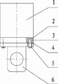
Landscapes
- Clamps And Clips (AREA)
Abstract
Description
Claims (2)
Priority Applications (1)
| Application Number | Priority Date | Filing Date | Title |
|---|---|---|---|
| CN 201120530480 CN202577301U (en) | 2011-12-19 | 2011-12-19 | Hammer block clamping device |
Applications Claiming Priority (1)
| Application Number | Priority Date | Filing Date | Title |
|---|---|---|---|
| CN 201120530480 CN202577301U (en) | 2011-12-19 | 2011-12-19 | Hammer block clamping device |
Publications (1)
| Publication Number | Publication Date |
|---|---|
| CN202577301U true CN202577301U (en) | 2012-12-05 |
Family
ID=47246730
Family Applications (1)
| Application Number | Title | Priority Date | Filing Date |
|---|---|---|---|
| CN 201120530480 Expired - Lifetime CN202577301U (en) | 2011-12-19 | 2011-12-19 | Hammer block clamping device |
Country Status (1)
| Country | Link |
|---|---|
| CN (1) | CN202577301U (en) |
-
2011
- 2011-12-19 CN CN 201120530480 patent/CN202577301U/en not_active Expired - Lifetime
Similar Documents
| Publication | Publication Date | Title |
|---|---|---|
| CN201303279Y (en) | Motor assembly and disassembly tools of narrow and small terminal surface location in space | |
| CN202114102U (en) | Deformation adjusting device for steel structure | |
| CN103331595A (en) | Header pipe cover press-in improved structure | |
| CN202137412U (en) | Drilling fixture for side holes of caterpillar sections | |
| CN202290487U (en) | Screw fixing device for spraying | |
| CN202543962U (en) | Seat pulp mold for equipment installation | |
| CN204108887U (en) | Electric locomotive pipe row assembly tool | |
| CN202388199U (en) | Fixture structure for mounting clamp | |
| CN104060819B (en) | Utilize the method for typified form construction shear wall and typified form used | |
| CN202290531U (en) | Eccentric block for vibration exciter | |
| CN202270924U (en) | Coaster chassis frame flexible tool | |
| CN202667975U (en) | Welding tool for valve rod connector | |
| CN209619909U (en) | A Simple Fixture for Formwork of Road Central Divider | |
| CN224170059U (en) | A lightweight fixing device for prefabricated composite slab molds | |
| CN201768853U (en) | Clamping device of coiling machine movable core cutter base | |
| CN202377270U (en) | Press oil cylinder replacement device | |
| CN204023787U (en) | A kind of workpiece Connection Block | |
| CN102489521B (en) | Mechanism for replacing reduction oil cylinder | |
| CN202380404U (en) | Pot type rubber bearing mortar template | |
| CN203462752U (en) | Tool type template | |
| CN202123448U (en) | Adjustable clamp for mounting hull skeleton | |
| CN203092480U (en) | Special tool for dismounting and mounting emergency distributing valve piston | |
| CN202367668U (en) | Nut switching device of hydraulic wrench | |
| CN203258200U (en) | Novel pipe clamp | |
| CN203330156U (en) | Limit structure for tension arm of wire drawing machine |
Legal Events
| Date | Code | Title | Description |
|---|---|---|---|
| C14 | Grant of patent or utility model | ||
| GR01 | Patent grant | ||
| EE01 | Entry into force of recordation of patent licensing contract |
Assignee: Fujian Yongqiang Geotchnical Engineering Co., Ltd. Assignor: Longyan Kaixin Engineering Machinery Co., Ltd. Contract record no.: 2013350000123 Denomination of utility model: Hammer block clamping device Granted publication date: 20121205 License type: Exclusive License Record date: 20130805 |
|
| LICC | Enforcement, change and cancellation of record of contracts on the licence for exploitation of a patent or utility model | ||
| EC01 | Cancellation of recordation of patent licensing contract |
Assignee: Fujian Yongqiang Geotchnical Engineering Co., Ltd. Assignor: Longyan Kaixin Engineering Machinery Co., Ltd. Contract record no.: 2013350000123 Date of cancellation: 20131128 |
|
| EE01 | Entry into force of recordation of patent licensing contract |
Assignee: Fujian Yongqiang Geotchnical Engineering Co., Ltd. Assignor: Longyan Kaixin Engineering Machinery Co., Ltd. Contract record no.: 2013350000160 Denomination of utility model: Hammer block clamping device Granted publication date: 20121205 License type: Exclusive License Record date: 20131128 |
|
| LICC | Enforcement, change and cancellation of record of contracts on the licence for exploitation of a patent or utility model | ||
| EM01 | Change of recordation of patent licensing contract |
Change date: 20140613 Contract record no.: 2013350000160 Assignee after: Fujian Yongqiang Geotechnical Co., Ltd. Assignee before: Fujian Yongqiang Geotchnical Engineering Co., Ltd. |
|
| LICC | Enforcement, change and cancellation of record of contracts on the licence for exploitation of a patent or utility model | ||
| CX01 | Expiry of patent term |
Granted publication date: 20121205 |
|
| CX01 | Expiry of patent term |