CN202557391U - Half-hang type log truck rear frame traction tube locking device - Google Patents
Half-hang type log truck rear frame traction tube locking device Download PDFInfo
- Publication number
- CN202557391U CN202557391U CN2012201110325U CN201220111032U CN202557391U CN 202557391 U CN202557391 U CN 202557391U CN 2012201110325 U CN2012201110325 U CN 2012201110325U CN 201220111032 U CN201220111032 U CN 201220111032U CN 202557391 U CN202557391 U CN 202557391U
- Authority
- CN
- China
- Prior art keywords
- traction tube
- screw rod
- groove
- briquetting
- hole
- Prior art date
- Legal status (The legal status is an assumption and is not a legal conclusion. Google has not performed a legal analysis and makes no representation as to the accuracy of the status listed.)
- Expired - Fee Related
Links
- 238000000034 method Methods 0.000 abstract description 2
- 230000032258 transport Effects 0.000 description 3
- 238000010586 diagram Methods 0.000 description 2
- 239000012634 fragment Substances 0.000 description 2
- 235000008331 Pinus X rigitaeda Nutrition 0.000 description 1
- 235000011613 Pinus brutia Nutrition 0.000 description 1
- 241000018646 Pinus brutia Species 0.000 description 1
- 229910000831 Steel Inorganic materials 0.000 description 1
- 230000015572 biosynthetic process Effects 0.000 description 1
- 230000007812 deficiency Effects 0.000 description 1
- 230000002950 deficient Effects 0.000 description 1
- 238000005516 engineering process Methods 0.000 description 1
- 239000010959 steel Substances 0.000 description 1
- 238000003466 welding Methods 0.000 description 1
Images


Landscapes
- Supports For Pipes And Cables (AREA)
Abstract
The utility model discloses a half-hang type log truck rear frame traction tube locking device which comprises a support frame, a screw rod, a clamping pad, a pressing block and a sleeve, wherein the pressing block stretches into the sleeve, the screw rod is connected to the sleeve through the clamping pad in a movable mode, and a traction tube can be tightly locked by the pressing block through the screw rod. The rigidity and the reliability of the locking device can be improved by means of the adding of the thickness of the sleeve. Due to the fact that a lower end face of the pressing block is fit with the outer surface of the traction tube, the contact area is large, and the friction between the lower end face of the pressing block and the outer surface of the traction tube is also large, and therefore the locking device can be more firm and reliable in the using process.
Description
Technical field
The utility model relates to a kind of latching device, vehicle frame traction tube latching device behind particularly a kind of semi-trailer logging transporter.
Background technology
Semi-trailer logging transporter now commonly used transports elongate articles such as log, steel pipe; It mainly is through realizing increasing the cargo length of transport vehicle drawing vehicle frame after behind the superimposed trailer again, is connected through a traction tube between back vehicle frame and the semi-trailer frame.In order to lock traction tube, behind superimposed trailer, be provided with latching device before and after the vehicle frame, shown in Figure 1 is the latching device of prior art; Comprise pipe 100, go out the slit with the angle ring cutting less than 180 degree on pipe 100 tube walls, the slit from latching device top to ring cutting cuts out breach again; Two shell fragments 101 have so just been arranged; The locking plate 102 that has through hole in the welding of breach both sides is in the use, after elder generation is stretched to Len req with traction tube; Re-use bolt two locking plates are tightened, realize locking traction tube with this.This loads owing to be on one section pipe, to process, so tube wall can not be too thick or too thin, too thick then elasticity is not enough, too thin then rigid deficiency; Simultaneously, the pipe of latching device has very most of the contact with traction tube, and feasible friction force between the two is limited, and when running into the transport trolley braking or turning round, pine is slided even comes off easily.
Summary of the invention
In order to overcome above-mentioned defective, the utility model provides vehicle frame traction tube latching device behind a kind of semi-trailer logging transporter, can effectively improve self intensity of latching device and the firm degree of locking.
The utility model is realized through following technical scheme:
Vehicle frame traction tube latching device comprises support, screw rod, briquetting and sleeve pipe behind a kind of semi-trailer logging transporter, and said support is " n " shape, is fixed on the sleeve pipe, and end face central authorities have vertical tapped through hole on the support; Said briquetting is elongated, and its cross-sectional plane is an oblong, and upper surface central authorities are provided with draw-in groove, and the lower surface is the seal face that the outside face of shape and traction tube coincide; Tapped through hole is threaded on said screw rod and the support, screw rod through behind the tapped through hole with briquetting on draw-in groove flexibly connect; Have rectangle hole on the said sleeve pipe, said briquetting stretches in the rectangle hole of said sleeve pipe.
The further improved technical scheme of the utility model is: the strip groove before and after said briquetting upper surface central authorities are provided with and run through, and the strip groove upper fixed has the card pad, forms draw-in groove; Said card pad fills up central authorities from the edge to card along the draw-in groove direction and is provided with breach, and its width is less than the width of draw-in groove.
Said screw rod bottom has annular groove, and snaps in the breach of card pad through annular groove, flexibly connects with the card pad.Said annular groove height is greater than the card mat thickness, and the diameter of screw rod is greater than the width of card pad breach.Said screw tip is provided with the nut of band horizontal through hole.
The utility model compared with prior art has following advantage:
One, the area of contact of the utility model and traction tube increases, and is that latching device is locked more firmly.
Two, the utility model casing thickness increases, and makes that self hardness of latching device is higher, not easily damaged.
Description of drawings
Fig. 1 is existing latching device scheme drawing.
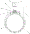
Fig. 2 is the utility model front elevational schematic.
Fig. 3 is the utility model schematic side view.
Fig. 4 is the local enlarged diagram of the utility model.
Fig. 5 is the local enlarged diagram of the utility model.
Fig. 6 is the utility model working state schematic representation.
1. supports among the figure, 10. tapped through hole, 2. screw rod, 20. horizontal through hole, 21. annular grooves, 22. nuts, 3. card pad, 4. briquetting, 41. draw-in grooves, 5. sleeve pipe, 6. traction tube, 100. pipes, 101. shell fragments, 102. locking plates.
The specific embodiment
As shown in Figure 2, the utility model one comprises support 1, screw rod 2, briquetting 4 and sleeve pipe 5, and said support 1 is " n " shape, is fixed on the sleeve pipe 5, and end face central authorities have vertical tapped through hole 10 on the support 1; Said briquetting 4 is elongated, and its cross-sectional plane is an oblong, and upper surface central authorities are provided with draw-in groove 41, and the lower surface is the seal face that the outside face of shape and traction tube 6 coincide; Tapped through hole 10 is threaded on said screw rod 2 and the support 1, and screw rod 2 flexibly connects through tapped through hole 10 backs and draw-in groove 41 on the briquetting 4; Have rectangle hole on the said sleeve pipe 5, said briquetting 4 stretches in the rectangle hole of said sleeve pipe 5.
As shown in Figure 4, the strip groove before and after said briquetting 4 upper surface central authorities are provided with and run through, the strip groove upper fixed has card pad 3, formation draw-in groove 41; Said card pad 3 fills up 3 central authorities from the edge to card along draw-in groove 41 directions and is provided with breach, and its width is less than the width of draw-in groove 41.
Said screw rod 2 bottoms have annular groove 21, and snap in the breach of card pad 3 through annular groove 21, flexibly connect with card pad 3.
Said annular groove 21 height are greater than card pad 3 thickness, and the diameter of screw rod 2 is greater than the width of card pad 3 breach.
Said screw rod 2 tops are provided with the nut 22 of band horizontal through hole 20.
The vehicle frame front and back respectively had one after the utility model was fixed on the semi-trailer logging transporter, sleeve pipe before and after traction tube is stretched into, and rotary screw is pressed on briquetting on the traction tube, just can realize the locking to back vehicle frame traction tube.The thickness that the utility model can increase sleeve pipe improves the hardness and the reliability of latching device self; Because it is identical that the lower surface of briquetting and traction tube outer shows; Area of contact is big, and both friction force are also big, so in use have higher fastness and reliability.
Claims (5)
1. vehicle frame traction tube latching device behind the semi-trailer logging transporter; It is characterized in that: comprise support (1), screw rod (2), briquetting (4) and sleeve pipe (5); Said support (1) is " n " shape; Be fixed on the sleeve pipe (5), support (1) is gone up end face central authorities and is had vertical tapped through hole (10); Said briquetting (4) is elongated, and its cross-sectional plane is an oblong, and upper surface central authorities are provided with draw-in groove (41), and the lower surface is the seal face that the outside face of shape and traction tube (6) coincide; Said screw rod (2) is gone up tapped through hole (10) with support (1) and is threaded, and screw rod (2) flexibly connects through the draw-in groove (41) on tapped through hole (10) back and the briquetting (4); Said sleeve pipe has rectangle hole on (5), and said briquetting (4) stretches in the rectangle hole of said sleeve pipe (5).
2. vehicle frame traction tube latching device behind a kind of semi-trailer logging transporter according to claim 1; It is characterized in that: the strip groove before and after said briquetting (4) upper surface central authorities are provided with and run through; The strip groove upper fixed has card pad (3), forms draw-in groove (41); Said card pad (3) fills up (3) central authorities from the edge to card along draw-in groove (41) direction and is provided with breach, and its width is less than the width of draw-in groove (41).
3. vehicle frame traction tube latching device behind a kind of semi-trailer logging transporter according to claim 1 and 2; It is characterized in that: said screw rod (2) bottom has annular groove (21); And snap in the breach of card pad (3) through annular groove (21), flexibly connect with card pad (3).
4. vehicle frame traction tube latching device behind a kind of semi-trailer logging transporter according to claim 3 is characterized in that: said annular groove (21) height is greater than card pad (3) thickness, and the diameter of screw rod (2) is greater than the width of card pad (3) breach.
5. vehicle frame traction tube latching device behind a kind of semi-trailer logging transporter according to claim 1 is characterized in that: said screw rod (2) top is provided with the nut (22) of band horizontal through hole (20).
Priority Applications (1)
| Application Number | Priority Date | Filing Date | Title |
|---|---|---|---|
| CN2012201110325U CN202557391U (en) | 2012-03-22 | 2012-03-22 | Half-hang type log truck rear frame traction tube locking device |
Applications Claiming Priority (1)
| Application Number | Priority Date | Filing Date | Title |
|---|---|---|---|
| CN2012201110325U CN202557391U (en) | 2012-03-22 | 2012-03-22 | Half-hang type log truck rear frame traction tube locking device |
Publications (1)
| Publication Number | Publication Date |
|---|---|
| CN202557391U true CN202557391U (en) | 2012-11-28 |
Family
ID=47207082
Family Applications (1)
| Application Number | Title | Priority Date | Filing Date |
|---|---|---|---|
| CN2012201110325U Expired - Fee Related CN202557391U (en) | 2012-03-22 | 2012-03-22 | Half-hang type log truck rear frame traction tube locking device |
Country Status (1)
| Country | Link |
|---|---|
| CN (1) | CN202557391U (en) |
Cited By (1)
| Publication number | Priority date | Publication date | Assignee | Title |
|---|---|---|---|---|
| CN113876538A (en) * | 2021-10-26 | 2022-01-04 | 上海电气集团股份有限公司 | Circumferential locking device and circumferential locking method of traction system |
-
2012
- 2012-03-22 CN CN2012201110325U patent/CN202557391U/en not_active Expired - Fee Related
Cited By (1)
| Publication number | Priority date | Publication date | Assignee | Title |
|---|---|---|---|---|
| CN113876538A (en) * | 2021-10-26 | 2022-01-04 | 上海电气集团股份有限公司 | Circumferential locking device and circumferential locking method of traction system |
Similar Documents
| Publication | Publication Date | Title |
|---|---|---|
| CN203936424U (en) | The drilling tool of electric motor end cap | |
| CN201650954U (en) | Rotary fastener | |
| CN104426462A (en) | Aluminum section for photovoltaic support | |
| CN204559474U (en) | A kind of photovoltaic bracket | |
| CN202867496U (en) | Platform fixing device | |
| CN203666723U (en) | Bearing holding trolley for automobile machining | |
| CN202837251U (en) | Ultrasonic probe support frame for vehicle wheel | |
| CN206437047U (en) | A kind of dual-purpose skibob | |
| CN212455172U (en) | A kind of protection type automobile bolt that is not easy to loosen | |
| CN202578315U (en) | Doorsill transition slope frame | |
| CN203946745U (en) | Anticollision strip mounting structure in lift car | |
| CN204383104U (en) | Federal bumper towing hook mounting structure | |
| CN204960841U (en) | Terminal fixing device of coiled tubing | |
| CN209099093U (en) | A kind of ramp plate | |
| CN203793333U (en) | Storage battery electric engineering vehicle | |
| CN201924925U (en) | Box body structure of single-roller off-pan shearer | |
| CN203854735U (en) | Chock fixing device for van | |
| CN103723174A (en) | Bearing supporting trolley used in process of car machining | |
| CN202243724U (en) | Compartment plate of container semitrailer | |
| CN101879708A (en) | Auxiliary mounting tool for nut supporting plate | |
| CN203223734U (en) | Extrusion part adopting large-area imprinting method | |
| CN208203265U (en) | Rail wheel fixator | |
| CN203419143U (en) | Installing mechanism for top plate of through passage | |
| CN203543715U (en) | Integrated busbar outside wrapped interface | |
| CN203948603U (en) | Anticreep pulley |
Legal Events
| Date | Code | Title | Description |
|---|---|---|---|
| C14 | Grant of patent or utility model | ||
| GR01 | Patent grant | ||
| C17 | Cessation of patent right | ||
| CF01 | Termination of patent right due to non-payment of annual fee |
Granted publication date: 20121128 Termination date: 20140322 |