CN202550348U - Folding multifunctional overhauling frame for overhauling isolating switch - Google Patents
Folding multifunctional overhauling frame for overhauling isolating switch Download PDFInfo
- Publication number
- CN202550348U CN202550348U CN 201220170393 CN201220170393U CN202550348U CN 202550348 U CN202550348 U CN 202550348U CN 201220170393 CN201220170393 CN 201220170393 CN 201220170393 U CN201220170393 U CN 201220170393U CN 202550348 U CN202550348 U CN 202550348U
- Authority
- CN
- China
- Prior art keywords
- step ladder
- isolating switch
- fixed
- frame
- rod
- Prior art date
- Legal status (The legal status is an assumption and is not a legal conclusion. Google has not performed a legal analysis and makes no representation as to the accuracy of the status listed.)
- Expired - Fee Related
Links
Images

Landscapes
- Ladders (AREA)
Abstract
本实用新型公开了一种隔离开关检修用的可折叠多功能检修架,其包括一步梯、铰接于步梯上部的悬挂杆、设于步梯下部的与隔离开关上的基础槽钢固定的紧固装置、设于步梯上部的可折叠工作平台以及设于步梯上的横杆与所述基础槽钢之间的斜支撑;所述工作平台的下部设有支撑杆,所述支撑杆的一端与工作平台的前端连接,另一端与步梯上的横杆固定;所述斜支撑通过锁紧装置固定在所述基础槽钢上。采用本实用新型可将安全腰带挂在悬挂杆上,安全性大大增加,并且工作时不再需要人扶持,解放了部分工作人员,提高了工作效率。
The utility model discloses a foldable multifunctional overhaul frame for isolating switch maintenance, which comprises a step ladder, a suspension rod hinged on the upper part of the step ladder, and a fastening frame fixed on the base channel steel on the isolating switch arranged at the lower part of the step ladder. fixed device, a foldable working platform on the upper part of the step ladder, and an oblique support between the cross bar on the step ladder and the basic channel steel; the lower part of the working platform is provided with a support rod, and the support rod One end is connected to the front end of the working platform, and the other end is fixed to the cross bar on the step ladder; the oblique support is fixed on the foundation channel steel through a locking device. By adopting the utility model, the safety belt can be hung on the suspension rod, the safety is greatly increased, and the support of people is no longer needed during work, which liberates some workers and improves the work efficiency.
Description
技术领域 technical field
本实用新型涉及一种隔离开关检修用的可折叠多功能检修架。 The utility model relates to a foldable multifunctional maintenance frame for isolating switch maintenance.
背景技术 Background technique
220kV隔离开关是两段支持绝缘子,对于这种高布置设备的检修中要用到人字梯,人字梯极其沉重,需要四人搬运,较为麻烦,费时费力。由于220kV隔离开关是双槽钢或方钢布置,普通的悬挂器无法使用。另外,工作过程中,这种人字梯必须有人扶持,这样会占用很多人员,工作效率低下。 The 220kV isolating switch is a two-stage supporting insulator. For the maintenance of such high-layout equipment, a ladder is used. The ladder is extremely heavy and requires four people to carry it, which is troublesome, time-consuming and laborious. Since the 220kV isolating switch is arranged with double channel steel or square steel, ordinary hangers cannot be used. In addition, in the working process, this kind of ladder must be supported by someone, which will take up a lot of people and cause low work efficiency.
发明内容 Contents of the invention
本实用新型要解决的技术问题是提供一种使用方便、结构简单的隔离开关检修用的可折叠多功能检修架。 The technical problem to be solved by the utility model is to provide a foldable multi-function maintenance frame for isolating switch maintenance which is convenient to use and simple in structure.
为解决上述技术问题,本实用新型所采取的技术方案是:一隔离开关检修用的可折叠多功能检修架,其关键技术在于:其包括一步梯、铰接于步梯上部的悬挂杆、设于步梯下部的与隔离开关上的基础槽钢固定的紧固装置、设于步梯上部的可折叠工作平台以及设于步梯上的横杆与所述基础槽钢之间的斜支撑;所述工作平台的下部设有支撑杆,所述支撑杆的一端与工作平台的前端连接,另一端与步梯上的横杆固定;所述斜支撑通过锁紧装置固定在所述基础槽钢上。 In order to solve the above-mentioned technical problems, the technical solution adopted by the utility model is: a foldable multifunctional maintenance frame for isolating switch maintenance. The fastening device at the lower part of the step ladder is fixed to the basic channel steel on the isolation switch, the foldable working platform on the upper part of the step ladder and the oblique support between the cross bar on the step ladder and the basic channel steel; The lower part of the working platform is provided with a supporting rod, one end of the supporting rod is connected to the front end of the working platform, and the other end is fixed to the cross bar on the step ladder; the oblique support is fixed on the basic channel steel through a locking device .
上述悬挂杆的上部固定有用于悬挂安全腰带的锁环。 The upper part of the above-mentioned suspension rod is fixed with a lock ring for hanging the safety belt.
上述锁紧装置包括支撑方钢以及设于支撑方钢上的固定带。 The above-mentioned locking device includes a supporting square steel and a fixing belt arranged on the supporting square steel.
上述紧固装置为一框型构件,该框型构件呈“口”字型,其由上部的横担、下部的活动支撑杆以及设于横担与活动支撑杆之间的螺杆构成,活动支撑杆可沿螺杠上下移动,所述活动支持杆上设有长圆孔,螺杆可在长圆孔内左右移动;所述横担借助两个连接杆与步梯固定连接。 The above-mentioned fastening device is a frame-shaped member, the frame-shaped member is in the shape of a "mouth", and it is composed of an upper cross arm, a lower movable support rod and a screw rod arranged between the cross arm and the movable support rod, and the movable support The rod can move up and down along the screw rod, and the movable support rod is provided with an oblong hole, and the screw rod can move left and right in the oblong hole; the cross arm is fixedly connected with the step ladder by means of two connecting rods.
采用上述技术方案所产生的有益效果在于:采用本实用新型可将安全腰带挂在悬挂杆上,安全性大大增加,并且工作时不再需要人扶持,解放了部分工作人员,提高了工作效率;本实用新型安装和拆卸方便,避免了以往搬运移动沉重升降梯的麻烦。 The beneficial effects produced by adopting the above technical solution are: the utility model can be used to hang the safety belt on the suspension rod, the safety is greatly increased, and no support is needed during work, which liberates part of the staff and improves the work efficiency; The utility model is convenient to install and disassemble, and avoids the trouble of carrying and moving heavy lifts in the past.
附图说明 Description of drawings
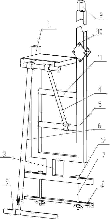
图1是本实用新型的结构示意图; Fig. 1 is a structural representation of the utility model;
其中,1、工作平台;2、锁环;3、连接杆;4、支撑杆;5、步梯;6、斜支撑;7、螺杆;8、活动支撑杆;9、锁紧装置;10、悬挂杆;11、横杆;12、横担。 Among them, 1. Working platform; 2. Lock ring; 3. Connecting rod; 4. Support rod; 5. Step ladder; 6. Inclined support; 7. Screw rod; 8. Movable support rod; Suspension bar; 11, cross bar; 12, cross arm.
具体实施方式 Detailed ways
下面结合附图和具体实施方式对本实用新型作进一步详细的说明。 Below in conjunction with accompanying drawing and specific embodiment, the utility model is described in further detail.
参见附图1,本实用新型包括一步梯5,步梯5为常用的步梯,其是由若干个平行的横杆11以及固定于横杆11两端的竖杆构成;步梯5的上部铰接有悬挂杆10,悬挂杆10上方固定有锁环2,锁环2上悬挂有安全腰带;所述步梯5下部固定有紧固装置8,该紧固装置8为一框型构件,该框型构件呈“口”字型,其由上部的横担12、下部的活动支撑杆8以及设于横担12与活动支撑杆8之间的两个螺杆7构成,活动支撑杆8可沿螺杠7上下移动,可牢固的固定在隔离开关的基础槽钢上,所述活动支持杆8上设有长圆孔,根据基础构件的宽度可螺杆7可在长圆孔内左右移动,所述横担12通过两个连接杆3与步梯5固定连接,连接杆3与步梯5之间焊接,紧固装置8固定安装在隔离开关上的基础槽钢上;在所述步梯5的上端部位固定有可折叠工作平台1,该工作平台1使用时张开,检修人员可以站在上面进行操作,不用时可收起并折叠;在步梯5上的横杆11与隔离开关上的基础槽钢之间设有一个斜支撑6;所述工作平台1的下部设有支撑杆4,所述支撑杆4的一端与工作平台1的前端连接,另一端与步梯5上的横杆11固定;所述斜支撑6通过锁紧装置9固定在所述基础槽钢上。
Referring to accompanying
所述锁紧装置9包括一个支撑方钢和系于支撑方钢上的固定带,使用时支撑方钢放置于基础槽钢的上方,固定带从基础槽钢下面绕过来然后再固定于支撑方钢上。 Described locking device 9 comprises a supporting square steel and the fixing belt that is tied on the supporting square steel, and supporting square steel is placed on the top of foundation channel steel during use, and fixing belt is wound around from the foundation channel steel and then fixed on the supporting side. on steel.
本实用新型使用方便,其下方的紧固装置8可根据基础槽钢的大小随意调节,固定牢固,工作时刻将安全腰带悬挂在锁环2上,安全性大大提高,不用时悬挂杆10可折叠。本实用新型体积小重量轻,并且方便安装和拆卸,避免了以往搬运移动沉重升降梯的麻烦,工作时也不再需要人扶持,解放了部分共工作人员,提高了工作效率。因此本实用新型在大工作量的年检中以及突发的消缺工作中有着广泛的用途。
The utility model is easy to use, the
Claims (4)
Priority Applications (1)
| Application Number | Priority Date | Filing Date | Title |
|---|---|---|---|
| CN 201220170393 CN202550348U (en) | 2012-04-21 | 2012-04-21 | Folding multifunctional overhauling frame for overhauling isolating switch |
Applications Claiming Priority (1)
| Application Number | Priority Date | Filing Date | Title |
|---|---|---|---|
| CN 201220170393 CN202550348U (en) | 2012-04-21 | 2012-04-21 | Folding multifunctional overhauling frame for overhauling isolating switch |
Publications (1)
| Publication Number | Publication Date |
|---|---|
| CN202550348U true CN202550348U (en) | 2012-11-21 |
Family
ID=47170917
Family Applications (1)
| Application Number | Title | Priority Date | Filing Date |
|---|---|---|---|
| CN 201220170393 Expired - Fee Related CN202550348U (en) | 2012-04-21 | 2012-04-21 | Folding multifunctional overhauling frame for overhauling isolating switch |
Country Status (1)
| Country | Link |
|---|---|
| CN (1) | CN202550348U (en) |
Cited By (4)
| Publication number | Priority date | Publication date | Assignee | Title |
|---|---|---|---|---|
| CN103117186A (en) * | 2013-02-22 | 2013-05-22 | 吉林省电力有限公司通化供电公司 | Insulating support for preventing fracture of porcelain insulator of isolating switch |
| CN103427353A (en) * | 2013-08-08 | 2013-12-04 | 国家电网公司 | Switch waist-tying rope bracket |
| CN105863485A (en) * | 2016-04-27 | 2016-08-17 | 中冶建工集团有限公司 | Herringbone ladder for garden maintenance |
| CN111463693A (en) * | 2020-05-25 | 2020-07-28 | 国网安徽省电力有限公司滁州供电公司 | Ascending platform for maintenance of isolating switch |
-
2012
- 2012-04-21 CN CN 201220170393 patent/CN202550348U/en not_active Expired - Fee Related
Cited By (5)
| Publication number | Priority date | Publication date | Assignee | Title |
|---|---|---|---|---|
| CN103117186A (en) * | 2013-02-22 | 2013-05-22 | 吉林省电力有限公司通化供电公司 | Insulating support for preventing fracture of porcelain insulator of isolating switch |
| CN103117186B (en) * | 2013-02-22 | 2015-12-30 | 吉林省电力有限公司通化供电公司 | One keeps apart official seal porcelain insulator breaking insulating support |
| CN103427353A (en) * | 2013-08-08 | 2013-12-04 | 国家电网公司 | Switch waist-tying rope bracket |
| CN105863485A (en) * | 2016-04-27 | 2016-08-17 | 中冶建工集团有限公司 | Herringbone ladder for garden maintenance |
| CN111463693A (en) * | 2020-05-25 | 2020-07-28 | 国网安徽省电力有限公司滁州供电公司 | Ascending platform for maintenance of isolating switch |
Similar Documents
| Publication | Publication Date | Title |
|---|---|---|
| CN204904756U (en) | Large -scale LED screen convenient to installation wall body | |
| CN201862167U (en) | Safety belt hanging stand for overhaul of isolating switch | |
| CN202967920U (en) | Hanging overhaul device of load switch of transformer | |
| CN211368423U (en) | Stay cable tower top lifting traction operation platform | |
| CN102738733B (en) | ± 660kV strain tower changes porcelain insulator suspension bracket | |
| CN205132955U (en) | Hoist and mount operation of electric power industry low latitude is with hoist and mount frame | |
| CN204118541U (en) | A kind of field work service kit | |
| CN202423906U (en) | Overhaul platform for isolating switch | |
| CN205822923U (en) | A kind of detachable safety cover bar | |
| CN204324741U (en) | Load switch of transformer suspended core apparatus | |
| CN203559351U (en) | Suspended bridge overhauling workbench | |
| CN203412356U (en) | Pole erecting device | |
| CN202825807U (en) | Tool rack | |
| CN205178344U (en) | Mutual -inductor overhauls platform | |
| CN205724585U (en) | Multi-function overhaul platform | |
| CN203577185U (en) | Shifting mechanism in times of power transmission and distribution line repair | |
| CN202333524U (en) | Hoisting support for overhaul of isolating switch | |
| CN206931904U (en) | Distribution box job platform | |
| CN203544991U (en) | Overturn device for workpiece tray conveyor line | |
| CN204679238U (en) | The pick-up unit of power construction seat belt hanger | |
| CN201549792U (en) | 220 kV transformer maintenance workbench | |
| CN111463689A (en) | A special tool for overhauling the hanging core of a distribution transformer | |
| CN207339073U (en) | A kind of comprehensive universal upending frame | |
| CN203218796U (en) | Operation platform for high-altitude line construction | |
| CN203639105U (en) | Suspension type temporary hoisting operation platform |
Legal Events
| Date | Code | Title | Description |
|---|---|---|---|
| C14 | Grant of patent or utility model | ||
| GR01 | Patent grant | ||
| ASS | Succession or assignment of patent right |
Owner name: HEBEI ELECTRIC POWER CORPORATION SHIJIAZHUANG POWE Effective date: 20130412 Owner name: STATE ELECTRIC NET CROP. Free format text: FORMER OWNER: SHIJIAZHUANG POWER SUPPLY COMPANY Effective date: 20130412 |
|
| C41 | Transfer of patent application or patent right or utility model | ||
| COR | Change of bibliographic data |
Free format text: CORRECT: ADDRESS; FROM: 050091 SHIJIAZHUANG, HEBEI PROVINCE TO: 100031 XICHENG, BEIJING |
|
| TR01 | Transfer of patent right |
Effective date of registration: 20130412 Address after: 100031 Xicheng District West Chang'an Avenue, No. 86, Beijing Patentee after: State Grid Corporation of China Patentee after: Hebei Electric Power Corporation Patentee after: Shijiazhuang Power Supply Co.,Ltd. Address before: 050091 No. 529 South China Avenue, Hebei, Shijiazhuang Patentee before: Shijiazhuang Power Supply Co.,Ltd. |
|
| CF01 | Termination of patent right due to non-payment of annual fee |
Granted publication date: 20121121 Termination date: 20180421 |
|
| CF01 | Termination of patent right due to non-payment of annual fee |