CN202541123U - Multifunctional compasses - Google Patents
Multifunctional compasses Download PDFInfo
- Publication number
- CN202541123U CN202541123U CN2012201638919U CN201220163891U CN202541123U CN 202541123 U CN202541123 U CN 202541123U CN 2012201638919 U CN2012201638919 U CN 2012201638919U CN 201220163891 U CN201220163891 U CN 201220163891U CN 202541123 U CN202541123 U CN 202541123U
- Authority
- CN
- China
- Prior art keywords
- connecting rod
- locating shaft
- pen
- utility
- model
- Prior art date
- Legal status (The legal status is an assumption and is not a legal conclusion. Google has not performed a legal analysis and makes no representation as to the accuracy of the status listed.)
- Expired - Fee Related
Links
Images

Abstract
The utility model provides a pair of multifunctional compasses comprising a connecting rod, a positioning shaft and a rotary pen. The connecting rod is detachably connected with the positioning shaft and the rotary pen; the connecting rod is provided with a runner and scale marks, and one end of the connecting rod is provided with a connecting clamp; the upper end of the positioning shaft is provided with a circular ring, the periphery of the upper end of the positioning shaft is provided with the scale marks, and the circular ring is provided with a clamping groove; the upper end of the rotary pen is provided with a sliding device; the clamping groove is connected with the connecting clamp; and the sliding device is connected with the runner. The multifunctional compasses have a flexible structure and high practicality, are convenient to carry about and store, can be used for drawing circles and regular polygons and have the functions of a ruler and a pen.
Description
Technical field
The utility model belongs to the stationery field, particularly a kind of multifunctional compass.
Background technology
Compasses are as a kind of the most frequently used drawing instrument; Extensively apply to fields such as study, drawing design, general compasses have only the function of picture circle, still; People often also need other figures of picture when drawing circle; Such as regular polygon, this just needs more aid such as ruler, protractor, and instrument is too many to be inconvenient to carry and difficult keeping.
The utility model content
To the problem that background technology exists, the utility model provides a kind of multifunctional compass.
For solving the problems of the technologies described above, the utility model adopts following technical scheme.
A kind of multifunctional compass comprises connecting rod, locating shaft, rotation pen, and connecting rod is removable the connection with locating shaft, rotation pen; Connecting rod is provided with chute and scale mark, and the one of which end is provided with Connection Card; The locating shaft upper end is an annulus, around it scale mark is arranged, and annulus is provided with draw-in groove; Rotation pen upper end is provided with carriage; Draw-in groove is connected with Connection Card; Carriage is connected with chute.
Optimal technical scheme as the utility model has:
Described locating shaft inside is cavity, and pilot pin is installed in the cavity; The locating shaft lower end is detachable.
Described carriage is a pulley.
Use the utility model to draw bowlder, locating shaft as fulcrum, is confirmed radius of a circle according to the scale mark of connecting rod, after will rotate pen and being fixed on corresponding scale position through carriage, rotation rotates a circle around locating shaft and to get final product; When needs picture polygon; Summit Equal round principle according to regular polygon; Utilize the scale mark of locating shaft upper end to confirm the summit, connect again, during such as the picture equilateral triangle; Connecting rod whenever rotates 120 degree around locating shaft and utilizes the fixed point of rotation pen, utilizes straight line to connect three points then and can obtain equilateral triangle; Connecting rod whenever revolves around locating shaft and turn 90 degrees fixed point, utilizes straight line to connect four points then and just can obtain square; By that analogy, can obtain regular polygon; When not needing picture circle or regular polygon, after locating shaft pulled down its lower end is disassembled, can use as pen after changing pilot pin into cavity that pen core is installed in locating shaft, the connecting rod that removes simultaneously can be used as ruler and uses.
Compared with prior art, the utlity model has following advantage and beneficial effect:
1, the utility model combines the function of compasses, protractor, ruler, pen, and can draw circle, regular polygon also have the function of ruler, pen simultaneously, and it is easy to use, and is practical.
2, the utility model structure is flexible, and is detachable, is easy to carry and keeping.
Description of drawings
Fig. 1 is the structure diagram of the utility model.
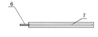
Fig. 2 is the front view of the utility model connecting rod.
Fig. 3 is the vertical view of the utility model connecting rod.
Fig. 4 is the structure diagram of the utility model locating shaft.
The structure diagram of Fig. 5 the utility model rotation pen.
Wherein, 1-connecting rod, 2-locating shaft, 3-rotation pen, 4-annulus, 5-draw-in groove, 6-Connection Card, 7-chute, 8-pilot pin, 9-carriage.
The specific embodiment
Below in conjunction with embodiment shown in the drawings the utility model is described further.
Shown in accompanying drawing, the utility model comprises connecting rod 1, locating shaft 2, rotation pen 3, and connecting rod 1 is removable the connection with locating shaft 2, rotation pen 3; Connecting rod 1 is provided with chute 7 and scale mark, and the one of which end is provided with Connection Card 6; Locating shaft 2 upper ends are annulus 4, have scale mark, annulus to be provided with draw-in groove 5 around it; Rotation pen 3 upper ends are provided with carriage 9; Draw-in groove 5 is connected with Connection Card 6; Carriage 9 is connected with chute 7; Locating shaft 2 inside are cavity, and pilot pin is installed in the cavity; The locating shaft lower end is detachable; Carriage in the present embodiment is a pulley.
Claims (3)
1. multifunctional compass is characterized in that: comprise connecting rod, locating shaft, rotation pen, connecting rod is removable the connection with locating shaft, rotation pen; Connecting rod is provided with chute and scale mark, and the one of which end is provided with Connection Card; The locating shaft upper end is an annulus, around it scale mark is arranged, and annulus is provided with draw-in groove; Rotation pen upper end is provided with carriage; Draw-in groove is connected with Connection Card; Carriage is connected with chute.
2. a kind of multifunctional compass according to claim 1 is characterized in that: described locating shaft is inner for cavity, and pilot pin is installed in the cavity; The locating shaft lower end is detachable.
3. a kind of multifunctional compass according to claim 1 is characterized in that: described carriage is a pulley.
Priority Applications (1)
| Application Number | Priority Date | Filing Date | Title |
|---|---|---|---|
| CN2012201638919U CN202541123U (en) | 2012-04-18 | 2012-04-18 | Multifunctional compasses |
Applications Claiming Priority (1)
| Application Number | Priority Date | Filing Date | Title |
|---|---|---|---|
| CN2012201638919U CN202541123U (en) | 2012-04-18 | 2012-04-18 | Multifunctional compasses |
Publications (1)
| Publication Number | Publication Date |
|---|---|
| CN202541123U true CN202541123U (en) | 2012-11-21 |
Family
ID=47161802
Family Applications (1)
| Application Number | Title | Priority Date | Filing Date |
|---|---|---|---|
| CN2012201638919U Expired - Fee Related CN202541123U (en) | 2012-04-18 | 2012-04-18 | Multifunctional compasses |
Country Status (1)
| Country | Link |
|---|---|
| CN (1) | CN202541123U (en) |
Cited By (1)
| Publication number | Priority date | Publication date | Assignee | Title |
|---|---|---|---|---|
| CN104972803A (en) * | 2015-05-16 | 2015-10-14 | 常州大学 | Manual calligraphy paper pulling device |
-
2012
- 2012-04-18 CN CN2012201638919U patent/CN202541123U/en not_active Expired - Fee Related
Cited By (2)
| Publication number | Priority date | Publication date | Assignee | Title |
|---|---|---|---|---|
| CN104972803A (en) * | 2015-05-16 | 2015-10-14 | 常州大学 | Manual calligraphy paper pulling device |
| CN104972803B (en) * | 2015-05-16 | 2016-08-24 | 常州大学 | A kind of manual actuator of calligraphy paper using |
Similar Documents
| Publication | Publication Date | Title |
|---|---|---|
| CN202896066U (en) | Multifunctional compasses for mathematical education | |
| CN202541123U (en) | Multifunctional compasses | |
| CN202439433U (en) | Teaching compass | |
| CN202448589U (en) | Multifunctional ruler | |
| CN201009594Y (en) | Compasses for blackboard | |
| CN203172274U (en) | Modified compasses | |
| CN203888466U (en) | Rotatable straight ruler | |
| CN202208214U (en) | Student combined ruler | |
| CN203293760U (en) | Pen capable of drawing straight lines and angles | |
| CN202345177U (en) | Adjustable compass for mathematical teaching | |
| CN204605305U (en) | A kind of Multipurpose ruler | |
| CN202319548U (en) | Multifunctional mathematical education scale | |
| CN203293764U (en) | Novel multifunctional pen | |
| CN203110706U (en) | Multifunctional mathematical teaching ruler | |
| CN203427499U (en) | Multifunctional compasses | |
| CN203185934U (en) | Multi-functional compasses | |
| CN202242601U (en) | Compasses | |
| CN201580155U (en) | Cyclograph for teaching | |
| CN202151978U (en) | Teaching compasses | |
| CN203511075U (en) | Sucker type compasses | |
| CN202557105U (en) | Multifunctional mathematics teaching aid | |
| CN202507786U (en) | Compasses of teaching tools | |
| CN201610018U (en) | Multi-purpose angle gauge device | |
| CN202480698U (en) | Multi-functional primary-school mathematic teaching tool | |
| CN202463330U (en) | Instrument capable of drawing concentric circles |
Legal Events
| Date | Code | Title | Description |
|---|---|---|---|
| C14 | Grant of patent or utility model | ||
| GR01 | Patent grant | ||
| C17 | Cessation of patent right | ||
| CF01 | Termination of patent right due to non-payment of annual fee |
Granted publication date: 20121121 Termination date: 20130418 |