CN202535187U - Front end cover for generator - Google Patents
Front end cover for generator Download PDFInfo
- Publication number
- CN202535187U CN202535187U CN2012202049095U CN201220204909U CN202535187U CN 202535187 U CN202535187 U CN 202535187U CN 2012202049095 U CN2012202049095 U CN 2012202049095U CN 201220204909 U CN201220204909 U CN 201220204909U CN 202535187 U CN202535187 U CN 202535187U
- Authority
- CN
- China
- Prior art keywords
- end cover
- end cap
- axis hole
- generator
- utility
- Prior art date
- Legal status (The legal status is an assumption and is not a legal conclusion. Google has not performed a legal analysis and makes no representation as to the accuracy of the status listed.)
- Expired - Fee Related
Links
- 230000001681 protective effect Effects 0.000 claims abstract description 10
- 230000002787 reinforcement Effects 0.000 claims abstract description 5
- 230000008878 coupling Effects 0.000 abstract 2
- 238000010168 coupling process Methods 0.000 abstract 2
- 238000005859 coupling reaction Methods 0.000 abstract 2
- 238000005516 engineering process Methods 0.000 description 2
- 238000009434 installation Methods 0.000 description 2
- 230000002950 deficient Effects 0.000 description 1
- 230000000694 effects Effects 0.000 description 1
- 238000000034 method Methods 0.000 description 1
Images


Landscapes
- Motor Or Generator Frames (AREA)
Abstract
The utility model discloses a front end cover for a generator. The front end cover comprises a cylindrical end cover; one end of the end cover is fixedly connected with a coupling protective cover; a shaft hole is formed in the center of the end cover; and the shaft hole and the inner wall of the end cover are fixedly connected through a plurality of reinforcement ribs. The end cover and the coupling protective cover are integrally formed. The front end cover for the generator is compact in structure, light in weight, high in mechanical strength, and convenient and easy to install and dismantle.
Description
Technical field
The utility model relates to a kind of part of generator, is specifically related to a kind of front end of shield.
Background technology
Existing generator, its coupler protective casing and end cap are the separate type designs, have defective on the structure, and mechanical strength is not enough, the installation and removal trouble.
Summary of the invention
The utility model technical problem to be solved provides a kind of front end of shield, and it can increase the mechanical strength of end cap.
For solving the problems of the technologies described above, the technical solution of the utility model front end of shield is:
Comprise columnar end cap, an end of end cap is fixedly connected coupler protective casing; The center of end cap is provided with axis hole, achieves a fixed connection through a plurality of reinforcements between the inwall of axis hole and end cap.
Said end cap and coupler protective casing are formed in one.
One end connection bearing hole of said axis hole; Dead eye is provided with axis hole is concentric.
The technique effect that the utility model can reach is:
The utility model compact conformation, in light weight, mechanical strength is high, and installation and removal are convenient and simple.
Description of drawings
Below in conjunction with accompanying drawing and embodiment the utility model is done further detailed explanation:
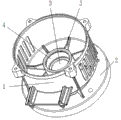
Fig. 1 is the sketch map of the utility model front end of shield;
Fig. 2 is the side schematic perspective view of the utility model;
Fig. 3 is the bottom surface schematic perspective view of the utility model.
Description of reference numerals among the figure:
1 is end cap, and 2 is coupler protective casing,
3 is axis hole, and 4 is dead eye,
5 is reinforcement.
Embodiment
To shown in Figure 3, the utility model front end of shield comprises columnar end cap 1 like Fig. 1, and an end of end cap 1 is fixedly connected coupler protective casing 2; The center of end cap 1 is provided with axis hole 3, achieves a fixed connection through a plurality of reinforcements 5 between the inwall of axis hole 3 and end cap 1;
One end connection bearing hole 4 of axis hole 3; Dead eye 4 and axis hole 3 concentric settings;
Claims (3)
1. a front end of shield is characterized in that: comprise columnar end cap, the end fixed connection coupler protective casing of end cap; The center of end cap is provided with axis hole, achieves a fixed connection through a plurality of reinforcements between the inwall of axis hole and end cap.
2. front end of shield according to claim 1 is characterized in that: said end cap and coupler protective casing are formed in one.
3. front end of shield according to claim 1 and 2 is characterized in that: an end connection bearing hole of said axis hole; Dead eye is provided with axis hole is concentric.
Priority Applications (1)
| Application Number | Priority Date | Filing Date | Title |
|---|---|---|---|
| CN2012202049095U CN202535187U (en) | 2012-05-09 | 2012-05-09 | Front end cover for generator |
Applications Claiming Priority (1)
| Application Number | Priority Date | Filing Date | Title |
|---|---|---|---|
| CN2012202049095U CN202535187U (en) | 2012-05-09 | 2012-05-09 | Front end cover for generator |
Publications (1)
| Publication Number | Publication Date |
|---|---|
| CN202535187U true CN202535187U (en) | 2012-11-14 |
Family
ID=47136344
Family Applications (1)
| Application Number | Title | Priority Date | Filing Date |
|---|---|---|---|
| CN2012202049095U Expired - Fee Related CN202535187U (en) | 2012-05-09 | 2012-05-09 | Front end cover for generator |
Country Status (1)
| Country | Link |
|---|---|
| CN (1) | CN202535187U (en) |
Cited By (1)
| Publication number | Priority date | Publication date | Assignee | Title |
|---|---|---|---|---|
| CN107342652A (en) * | 2017-08-09 | 2017-11-10 | 江苏环球特种电机有限公司 | A kind of low noise threephase asynchronous |
-
2012
- 2012-05-09 CN CN2012202049095U patent/CN202535187U/en not_active Expired - Fee Related
Cited By (1)
| Publication number | Priority date | Publication date | Assignee | Title |
|---|---|---|---|---|
| CN107342652A (en) * | 2017-08-09 | 2017-11-10 | 江苏环球特种电机有限公司 | A kind of low noise threephase asynchronous |
Similar Documents
| Publication | Publication Date | Title |
|---|---|---|
| CN203722374U (en) | Driving motor of mower | |
| CN202414082U (en) | Battery fixing device for electric bicycle | |
| CN202985983U (en) | Sprue sleeve structure | |
| CN203214662U (en) | Vertical bearing block | |
| CN204019475U (en) | Guiding dismounting cover and exhaust suspension hook mounting structure | |
| CN202153683U (en) | Motor end cap | |
| CN204059994U (en) | A kind of group is to platform | |
| CN202387578U (en) | Feeding pipe device for piston material-pushing centrifugal machine | |
| CN202713765U (en) | Static-electricity conducting device | |
| CN203230725U (en) | Pivot | |
| CN203146635U (en) | Short joint structure diaphragm coupling | |
| CN202955016U (en) | Protection hood of coupler | |
| CN202621114U (en) | Ceramic sand granulating machine | |
| CN203326770U (en) | Rear housing for outdoor motor | |
| CN202542858U (en) | Bottom foundation ring for nitric acid absorption tower | |
| CN204025577U (en) | Motor power output cavity body structure | |
| CN203656125U (en) | Reduction gearbox body | |
| CN201839119U (en) | End cover structure of explosion-proof permanent magnetic motor | |
| CN201866374U (en) | Valve cap for valve body | |
| CN201812885U (en) | Annular lithium thionyl chloride battery structure | |
| CN202986683U (en) | Wheel connector for electric children vehicle | |
| CN202638409U (en) | Heating reactor | |
| CN201855622U (en) | Lower end cover of filter | |
| CN202597078U (en) | Power end cover of pump | |
| CN102545452A (en) | Wind driven generator enclosure |
Legal Events
| Date | Code | Title | Description |
|---|---|---|---|
| C14 | Grant of patent or utility model | ||
| GR01 | Patent grant | ||
| C17 | Cessation of patent right | ||
| CF01 | Termination of patent right due to non-payment of annual fee |
Granted publication date: 20121114 Termination date: 20140509 |