CN202518817U - Quickly-positioning device for full-automatic sandwich glass production line - Google Patents
Quickly-positioning device for full-automatic sandwich glass production line Download PDFInfo
- Publication number
- CN202518817U CN202518817U CN2011205109483U CN201120510948U CN202518817U CN 202518817 U CN202518817 U CN 202518817U CN 2011205109483 U CN2011205109483 U CN 2011205109483U CN 201120510948 U CN201120510948 U CN 201120510948U CN 202518817 U CN202518817 U CN 202518817U
- Authority
- CN
- China
- Prior art keywords
- roller
- positioning device
- glass
- production line
- long roller
- Prior art date
- Legal status (The legal status is an assumption and is not a legal conclusion. Google has not performed a legal analysis and makes no representation as to the accuracy of the status listed.)
- Withdrawn - After Issue
Links
- 239000011521 glass Substances 0.000 title claims abstract description 30
- 238000004519 manufacturing process Methods 0.000 title claims abstract description 12
- 230000005540 biological transmission Effects 0.000 claims abstract description 17
- 239000005340 laminated glass Substances 0.000 claims abstract description 10
- 238000000034 method Methods 0.000 description 6
- 230000009286 beneficial effect Effects 0.000 description 1
- 238000004140 cleaning Methods 0.000 description 1
- 238000012986 modification Methods 0.000 description 1
- 230000004048 modification Effects 0.000 description 1
- 239000013589 supplement Substances 0.000 description 1
Images


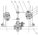
Classifications
-
- Y—GENERAL TAGGING OF NEW TECHNOLOGICAL DEVELOPMENTS; GENERAL TAGGING OF CROSS-SECTIONAL TECHNOLOGIES SPANNING OVER SEVERAL SECTIONS OF THE IPC; TECHNICAL SUBJECTS COVERED BY FORMER USPC CROSS-REFERENCE ART COLLECTIONS [XRACs] AND DIGESTS
- Y02—TECHNOLOGIES OR APPLICATIONS FOR MITIGATION OR ADAPTATION AGAINST CLIMATE CHANGE
- Y02P—CLIMATE CHANGE MITIGATION TECHNOLOGIES IN THE PRODUCTION OR PROCESSING OF GOODS
- Y02P40/00—Technologies relating to the processing of minerals
- Y02P40/50—Glass production, e.g. reusing waste heat during processing or shaping
- Y02P40/57—Improving the yield, e-g- reduction of reject rates
Landscapes
- Rollers For Roller Conveyors For Transfer (AREA)
Abstract
本实用新型涉及一种玻璃机械,针对现有技术中用于输送玻璃的滚筒传送带只能够在单一方向上传送玻璃的缺点,提供一种可以调节角度,从而改变玻璃传送方向的全自动夹层玻璃生产线快速定位装置。方案为:一种全自动夹层玻璃生产线快速定位装置,设置在用于输送玻璃的传送带部分,传送带包括长滚筒、用于支撑长滚筒的支架,其特征在于,有一水平转盘上设置若干轴承架,轴承架支撑水平轮轴,水平轮轴上设置滚轮,其一端部设置从动皮带轮,在从动皮带轮的斜下方对应设置主动皮带轮,且从动皮带轮、主动皮带轮之间通过传送皮带连接,所述转盘的中心设置一竖直的旋转螺柱,通过该旋转螺柱,转盘活动连接在构成所述支架的支架纵轴上。
The utility model relates to a glass machine, aiming at the disadvantage that the roller conveyor belt used for conveying glass in the prior art can only convey glass in a single direction, and provides a fully automatic laminated glass production line which can adjust the angle so as to change the conveying direction of the glass Quick positioning device. The solution is: a fast positioning device for a fully automatic laminated glass production line, which is installed on the conveyor belt part for conveying glass. The conveyor belt includes a long roller and a bracket for supporting the long roller. It is characterized in that a number of bearing frames are arranged on a horizontal turntable. The bearing frame supports the horizontal wheel shaft. Rollers are arranged on the horizontal wheel shaft. A driven pulley is arranged at one end of the horizontal wheel shaft. A driving pulley is arranged obliquely below the driven pulley, and the driven pulley and the driving pulley are connected by a transmission belt. A vertical rotating stud is arranged in the center, through which the turntable is movably connected to the longitudinal axis of the support constituting the support.
Description
技术领域 technical field
本实用新型涉及一种玻璃机械,尤其是一种用于传送玻璃的全自动夹层玻璃生产线快速定位装置。 The utility model relates to a glass machine, in particular to a quick positioning device for a full-automatic laminated glass production line used for conveying glass. the
背景技术 Background technique
现有的玻璃清洗机普遍采用滚筒传送带输送玻璃。一般情况下,在输送过程中,玻璃只在单一的直线方向上进行移动。然而在实际的生产、作业过程中,时常需要因不同的工序而改变移动方向;同时在空间有限的厂房内,为了提高空间利用率,不可避免的会将传送带设置成弯曲迂回的形式。传统的解决办法是借助人工,手动调节滚筒传送带上的玻璃的位置以达到转向的目的。当所清洗的玻璃面积比较小,数量少时,人工辅助的方法勉强可行,然而,当玻璃面积很大,且达到一定的数量时,人工手调的方式费时费力,并且容易造成失误而损坏玻璃。 Existing glass cleaning machines generally adopt roller conveyor belts to convey glass. Normally, the glass only moves in a single linear direction during the conveying process. However, in the actual production and operation process, it is often necessary to change the moving direction due to different processes; at the same time, in a factory with limited space, in order to improve space utilization, it is inevitable to set the conveyor belt in a curved and circuitous form. The traditional solution is to manually adjust the position of the glass on the roller conveyor belt to achieve the purpose of turning. When the area of glass to be cleaned is relatively small and the quantity is small, the manual assisted method is barely feasible. However, when the area of glass is large and reaches a certain quantity, manual adjustment is time-consuming and laborious, and it is easy to cause mistakes and damage the glass. the
发明内容 Contents of the invention
本实用新型主要针对现有技术中用于输送玻璃的滚筒传送带只能够在单一方向上传送玻璃的缺点,发明了一种可以调节角度,从而改变玻璃传送方向的全自动夹层玻璃生产线快速定位装置。 The utility model mainly aims at the disadvantage that the roller conveyor belt used for conveying glass in the prior art can only convey glass in a single direction, and invents a quick positioning device for a fully automatic laminated glass production line that can adjust the angle to change the direction of glass conveyance. the
本实用新型的上述技术问题是通过以下技术方案得以实施的:一种全自动夹层玻璃生产线快速定位装置,设置在用于输送玻璃的传送带部分,所述的传送带包括长滚筒、用于支撑长滚筒的支架,其特征在于,有一水平转盘,转盘上设置有若干轴承架,所述轴承架支撑水平轮轴,该水平轮轴上设置有滚轮,其一端部设置有从动皮带轮,在从动皮带轮的斜下方对应设置有主动皮带轮,且从动皮带轮、主动皮带轮之间通过传送皮带连接,所述转盘的中心设置有一竖直的旋转螺柱,通过该旋转螺柱,所述转盘活动连接在构成所述支架的支架纵轴上。 The above-mentioned technical problems of the utility model are implemented through the following technical solutions: a fast positioning device for a fully automatic laminated glass production line, which is installed on the conveyor belt part for conveying glass, and the conveyor belt includes a long roller for supporting the long roller The bracket is characterized in that there is a horizontal turntable, and several bearing frames are arranged on the turntable, and the bearing frames support a horizontal wheel shaft, and a roller is arranged on the horizontal wheel shaft, and a driven pulley is arranged at one end thereof, and a driven pulley is arranged on the oblique Correspondingly, there is a driving pulley at the bottom, and the driven pulley and the driving pulley are connected by a transmission belt. A vertical rotating stud is arranged in the center of the turntable, through which the turntable is movably connected to the on the longitudinal axis of the bracket. the
作为优选,所述的水平转盘上设置有两个轴承架,轮轴可转动的定位在两个轴承架上,轮轴的中部固定滚轮,并且滚轮的半径与长滚筒的半径相同,滚轮与长滚筒位于同一水平高度。所设置的滚轮能够在水平面内转动,调整了一定角度后的滚轮在输送玻璃的同时逐渐改变了玻璃的前进方向。 As a preference, the horizontal turntable is provided with two bearing frames, the wheel shaft is rotatably positioned on the two bearing frames, the middle part of the wheel shaft is fixed with a roller, and the radius of the roller is the same as that of the long roller, and the roller and the long roller are located the same level. The provided rollers can rotate in the horizontal plane, and the rollers adjusted to a certain angle gradually change the advancing direction of the glass while conveying the glass. the
作为优选,所述的支架纵轴与长滚筒间隔排列设置在支架上,一根支架纵轴上至少对称设置有两个快速定位装置,长滚筒的下方设置有与该长滚筒平行的传动轴。为稳定支撑玻璃,支架纵轴上的快速定位装置需要对称设置,例如,将快速定位装置设置在支架纵轴的两个端部,或者设置在前半段、后半段的中部等位置。 Preferably, the longitudinal axis of the support and the long roller are arranged on the support at intervals, at least two quick positioning devices are arranged symmetrically on the longitudinal axis of a support, and a transmission shaft parallel to the long roller is arranged under the long roller. In order to stably support the glass, the quick positioning device on the longitudinal axis of the support needs to be arranged symmetrically. For example, the quick positioning device is arranged at the two ends of the longitudinal axis of the support, or in the middle of the front half and the back half. the
作为优选,所述的传动轴上固定有若干主动皮带轮,所述的主动皮带轮与其斜上方的快速定位装置上的从动皮带轮一一对应。主动皮带轮通过传动皮带拉动从动皮带轮、轮轴发生偏移,轮轴上的滚轮随着偏转一定角度;玻璃随着长滚筒直线移动,当玻璃与偏转了角度的滚轮相接处后,玻璃能够继续移动,并且按照滚轮设定的方向逐渐发生偏转,最终实现整块玻璃转弯输送。 As a preference, several driving pulleys are fixed on the transmission shaft, and the driving pulleys are in one-to-one correspondence with the driven pulleys on the quick positioning device obliquely above them. The driving pulley pulls the driven pulley through the transmission belt, and the wheel shaft deviates, and the roller on the wheel shaft deflects at a certain angle; the glass moves in a straight line with the long roller, and when the glass meets the deflected roller, the glass can continue to move , and gradually deflect according to the direction set by the rollers, and finally realize the turning and conveying of the whole piece of glass. the
综上所述,本实用新型与现有技术相比具有如下优点。 In summary, compared with the prior art, the utility model has the following advantages. the
本实用新型在原有单一方向传送的基础上,增加了可以水平转动的滚轮,用以调节玻璃的前进方向;采用本实用新型提供的快速定位装置,有利于节省劳动力成本、提高工作效率。 On the basis of the original single-direction transmission, the utility model adds horizontally rotating rollers to adjust the forward direction of the glass; the utility model adopts the fast positioning device, which is beneficial to save labor costs and improve work efficiency. the
本实用新型的结构简单、可灵活调节。 The utility model has simple structure and can be adjusted flexibly. the
附图说明 Description of drawings
图1是本实用新型安装于玻璃传送带的结构示意图。 Fig. 1 is a structural schematic view of the utility model installed on a glass conveyor belt. the
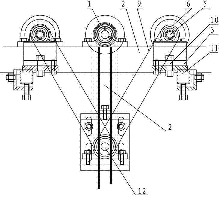
图2是本实用新型的主视图。 Fig. 2 is the front view of the utility model. the
图3是本实用新型的侧视图。 Fig. 3 is a side view of the utility model. the
图4是本实用新型的俯视图。 Fig. 4 is a top view of the utility model. the
图5是本实用新型的一种排布方式。 Figure 5 is an arrangement of the utility model. the
图6是本实用新型的另一种排布方式。 Fig. 6 is another arrangement of the utility model. the
图中标号为:1、长滚筒;2、支架;3、水平转盘;4、轴承架;5、水平轮轴;6、滚轮;7、从动皮带轮;8、主动皮带轮;9、传送皮带;10、旋转螺柱;11、支架纵轴;12、传动轴。 The labels in the figure are: 1, long roller; 2, bracket; 3, horizontal turntable; 4, bearing frame; 5, horizontal wheel shaft; 6, roller; 7, driven pulley; 8, driving pulley; 9, transmission belt; 10 , Rotating stud; 11, the longitudinal axis of the bracket; 12, the transmission shaft. the
具体实施方式 Detailed ways
下面结合附图和实施例对本实用新型进一步说明。 Below in conjunction with accompanying drawing and embodiment the utility model is further described. the
实施例1。 Example 1. the
如图1所示,全自动夹层玻璃生产线快速定位装置,设置在用于输送玻璃的传送带部分,所述的传送带包括长滚筒1、用于支撑长滚筒的支架2。
As shown in Figure 1, the quick positioning device of the fully automatic laminated glass production line is set on the conveyor belt part for conveying glass, and the conveyor belt includes a long roller 1 and a
如图2、3、4所示,有一水平转盘3,转盘上设置有两个并排的轴承架4,所述轴承架4支撑一根水平轮轴5,该水平轮轴5的中部固定一个滚轮6,滚轮6的半径与长滚筒1的半径相同,滚轮6与长滚筒1位于同一水平高度。
As shown in Figures 2, 3, and 4, there is a
所述水平轮轴5的一端固定一个从动皮带轮7,在从动皮带轮7的斜下方对应设置有主动皮带轮8,且从动皮带轮7、主动皮带轮8之间通过传送皮带9连接,所述水平转盘5的中心设置有一根竖直的旋转螺柱10,通过该旋转螺柱10将水平转盘10活动连接在构成所述支架2的支架纵轴11上。
One end of the
如图5所示,所述的支架纵轴11与长滚筒1间隔排列在支架2上,一根支架纵轴11上至少对称设置有两个快速定位装置,长滚筒1的下方设置有与该长滚筒1相平行的传动轴12。
As shown in Figure 5, the support
图5所示,所述传动轴12斜上方的左右两根支架纵轴11的端部分别设置有定位装置,左右两个定位装置的从动皮带轮7与中间的传动轴12上的主动皮带轮8一一对应,并且采用传送皮带9进行连接。
As shown in Fig. 5, the ends of the left and right bracket
图6所示,在同一支架纵轴11的两端对称设置快速定位装置,并且,快速定位装置的从动皮带轮7与该支架纵轴11斜下方的一根传动轴12上的主动皮带轮8一一对应,并且采用传送皮带9进行连接。
As shown in Fig. 6, the quick positioning device is arranged symmetrically at both ends of the same support
本实用新型所属技术领域的技术人员可以对所描述的具体实施例做各种各样的修改或补充或采用类似的方式替代,但并不会偏离本实用新型的精神或者超越所附权利要求书所定义的范围。 Those skilled in the technical field to which the utility model belongs can make various modifications or supplements to the described specific embodiments or adopt similar methods to replace them, but they will not deviate from the spirit of the utility model or go beyond the appended claims defined range. the
Claims (4)
Priority Applications (1)
| Application Number | Priority Date | Filing Date | Title |
|---|---|---|---|
| CN2011205109483U CN202518817U (en) | 2011-12-09 | 2011-12-09 | Quickly-positioning device for full-automatic sandwich glass production line |
Applications Claiming Priority (1)
| Application Number | Priority Date | Filing Date | Title |
|---|---|---|---|
| CN2011205109483U CN202518817U (en) | 2011-12-09 | 2011-12-09 | Quickly-positioning device for full-automatic sandwich glass production line |
Publications (1)
| Publication Number | Publication Date |
|---|---|
| CN202518817U true CN202518817U (en) | 2012-11-07 |
Family
ID=47101778
Family Applications (1)
| Application Number | Title | Priority Date | Filing Date |
|---|---|---|---|
| CN2011205109483U Withdrawn - After Issue CN202518817U (en) | 2011-12-09 | 2011-12-09 | Quickly-positioning device for full-automatic sandwich glass production line |
Country Status (1)
| Country | Link |
|---|---|
| CN (1) | CN202518817U (en) |
Cited By (1)
| Publication number | Priority date | Publication date | Assignee | Title |
|---|---|---|---|---|
| CN102491089A (en) * | 2011-12-09 | 2012-06-13 | 金华市怡达玻璃机械有限公司 | Quick positioning device for full-automatic sandwich glass production line |
-
2011
- 2011-12-09 CN CN2011205109483U patent/CN202518817U/en not_active Withdrawn - After Issue
Cited By (1)
| Publication number | Priority date | Publication date | Assignee | Title |
|---|---|---|---|---|
| CN102491089A (en) * | 2011-12-09 | 2012-06-13 | 金华市怡达玻璃机械有限公司 | Quick positioning device for full-automatic sandwich glass production line |
Similar Documents
| Publication | Publication Date | Title |
|---|---|---|
| CN205346254U (en) | Automatic lifting device of two roll tables of elongated shape article | |
| CN202625160U (en) | Material transport sliding channel | |
| CN201947440U (en) | Conveying turnplate positioning mechanism for full-automatic landing edge rubber coating machine | |
| CN201686312U (en) | Flat glass automatic reversing conveying device | |
| CN204938354U (en) | Calculator automatic assembly production line | |
| CN102491089B (en) | Quick positioning device for full-automatic sandwich glass production line | |
| CN204167282U (en) | For the cell piece material loading transport sector of photovoltaic string welding machine | |
| CN205771400U (en) | A kind of revolution conveyer device | |
| CN217397712U (en) | Automatic turning device for steel coil | |
| CN208814295U (en) | A kind of carton nail automatic mould turnover feeding mechanism of case | |
| CN205128766U (en) | Punch press numerical control feeder | |
| CN201385800Y (en) | Conveyor capable of automatically stacking stuff | |
| CN202464782U (en) | Glass cleaning drying machine with conveying device | |
| CN210480298U (en) | Suction positioning and conveying device for carton production line | |
| CN219602646U (en) | Be suitable for wrist-watch TP screen and carry upset gyro wheel line device | |
| CN202192065U (en) | Cleaning production line for solar cell panel | |
| CN217894424U (en) | A gyro wheel that is used for Mini LED backplate glass to convey | |
| CN105059951A (en) | Vertical stacking machine for plate glass | |
| CN203245694U (en) | Double-station steel tube flat head chamfering device | |
| CN202807634U (en) | Continuous automatic feeding device for plates | |
| CN104526207A (en) | Jockey wheel welding machine | |
| CN209922178U (en) | Tire lane dividing equipment | |
| CN209922488U (en) | A swing head cloth belt conveyor | |
| CN207789944U (en) | A kind of air duct plain cloth machine | |
| CN202640113U (en) | Feeding frame for conveying steel tubes to polish |
Legal Events
| Date | Code | Title | Description |
|---|---|---|---|
| C14 | Grant of patent or utility model | ||
| GR01 | Patent grant | ||
| AV01 | Patent right actively abandoned |
Granted publication date: 20121107 Effective date of abandoning: 20131127 |
|
| AV01 | Patent right actively abandoned |
Granted publication date: 20121107 Effective date of abandoning: 20131127 |
|
| RGAV | Abandon patent right to avoid regrant |