CN202515025U - Energy-saving high-efficiency washing cabinet - Google Patents
Energy-saving high-efficiency washing cabinet Download PDFInfo
- Publication number
- CN202515025U CN202515025U CN201220178950XU CN201220178950U CN202515025U CN 202515025 U CN202515025 U CN 202515025U CN 201220178950X U CN201220178950X U CN 201220178950XU CN 201220178950 U CN201220178950 U CN 201220178950U CN 202515025 U CN202515025 U CN 202515025U
- Authority
- CN
- China
- Prior art keywords
- washing
- cabinet
- pulley
- waste water
- pedal
- Prior art date
- Legal status (The legal status is an assumption and is not a legal conclusion. Google has not performed a legal analysis and makes no representation as to the accuracy of the status listed.)
- Expired - Fee Related
Links
Images


Classifications
-
- Y—GENERAL TAGGING OF NEW TECHNOLOGICAL DEVELOPMENTS; GENERAL TAGGING OF CROSS-SECTIONAL TECHNOLOGIES SPANNING OVER SEVERAL SECTIONS OF THE IPC; TECHNICAL SUBJECTS COVERED BY FORMER USPC CROSS-REFERENCE ART COLLECTIONS [XRACs] AND DIGESTS
- Y02—TECHNOLOGIES OR APPLICATIONS FOR MITIGATION OR ADAPTATION AGAINST CLIMATE CHANGE
- Y02B—CLIMATE CHANGE MITIGATION TECHNOLOGIES RELATED TO BUILDINGS, e.g. HOUSING, HOUSE APPLIANCES OR RELATED END-USER APPLICATIONS
- Y02B40/00—Technologies aiming at improving the efficiency of home appliances, e.g. induction cooking or efficient technologies for refrigerators, freezers or dish washers
Landscapes
- Cleaning By Liquid Or Steam (AREA)
Abstract
本实用新型涉及一种节能高效洗涤橱柜,包括柜体、台面、洗涤槽、出水龙头、碗架、废水过滤桶和废水收集箱等;废水收集箱外侧的柜体底板上设有脚踏板,脚踏板的顶端外侧设有连接板,脚踏板通过轴销连接着连杆的一端,连杆的另一端连接着安装于传动机构安装箱中部的曲轴,曲轴的输出轴上设有传动皮带轮;传动皮带轮与安装于上端盖内的输出皮带轮相配合由皮带连接,输出皮带轮的中心轴一端部设有洗涤毛刷,洗涤毛刷位于洗涤槽的上方。本实用新型设计合理,结构简单。采用曲柄摇杆机构原理,脚踏式驱动机构驱动毛刷旋转对餐具进行洗涤,省力没有噪音,毛刷规格多样,清洗效果好。
The utility model relates to an energy-saving and high-efficiency washing cabinet, which includes a cabinet body, a countertop, a washing tank, a water outlet tap, a bowl rack, a waste water filter bucket, a waste water collection box, etc.; There is a connecting plate outside the top of the pedal, the pedal is connected to one end of the connecting rod through a pivot pin, the other end of the connecting rod is connected to the crankshaft installed in the middle of the transmission mechanism installation box, and the output shaft of the crankshaft is provided with a drive pulley The transmission pulley is matched with the output pulley installed in the upper end cover and is connected by a belt. One end of the central shaft of the output pulley is provided with a washing brush, and the washing brush is located above the washing tank. The utility model has reasonable design and simple structure. Adopting the principle of the crank rocker mechanism, the foot-operated driving mechanism drives the brush to rotate to wash the tableware, which saves labor and makes no noise. The brushes have various specifications and the cleaning effect is good.
Description
技术领域 technical field
本实用新型涉及餐具洗涤设备技术领域,具体地说是一种节能高效洗涤橱柜。 The utility model relates to the technical field of tableware washing equipment, in particular to an energy-saving and high-efficiency washing cabinet.
背景技术 Background technique
现有的洗涤橱柜结构单一,移动不方便,功能少,而现在市场上家用洗碗机价格昂贵,市场上销售的洗碗机一般都在2000元左右,一般的家庭很难接受这样的价位。并且由于洗碗机由于结构设计、材料使用上存在一定的缺陷,内胆附着的油腻很难清洗,每天都用的洗碗机就经常出现“机洗碗,人洗机”的现象;洗涤时间过长。机洗一次需要一个多小时。许多厨具洗不干净,并且大多洗碗机都采用电动机带动水泵把水升到一定压力然后通过喷淋的方式去除厨具上的油污,并且碗深处的油污很难清洗到,具有很大的盲目性,对电和水的消耗量大。电动机驱动噪音和振动较大。 Existing washing cabinets have a single structure, are inconvenient to move, and have few functions. Now, household dishwashers are expensive on the market, and the dishwashers sold on the market are generally around 2,000 yuan. It is difficult for ordinary families to accept such a price. And because the dishwasher has certain defects in structural design and material use, the greasy inner tank is difficult to clean, and the phenomenon of "machine washing dishes, human washing machine" often occurs in dishwashers that are used every day; washing time too long. It takes more than an hour to machine wash once. Many kitchen utensils are not clean, and most dishwashers use a motor to drive a water pump to raise the water to a certain pressure and then remove the oil stains on the kitchen utensils by spraying, and the oil stains deep in the bowl are difficult to clean, which is very blind. Sexuality, large consumption of electricity and water. The motor drive noise and vibration are large.
实用新型内容 Utility model content
为了提高洗涤橱柜的洗涤效果,使用达到节能环保的要求、本实用新型提供一种节能高效洗涤橱柜。 In order to improve the washing effect of the washing cabinet and meet the requirements of energy saving and environmental protection, the utility model provides an energy-saving and high-efficiency washing cabinet.
本实用新型所采用的技术方案为: The technical scheme adopted in the utility model is:
一种节能高效洗涤橱柜,包括柜体、台面、洗涤槽4、出水龙头2、碗架6和柜门;所述洗涤槽4位于柜体的一侧,其下设有废水过滤桶13和废水收集箱12,三者通过管道连通;所述柜体内的另一侧设有二层碗架6,碗架的底部设有集流板17,集流板倾斜向下连接至废水收集箱12;改进在于:
An energy-saving and high-efficiency washing cabinet, comprising a cabinet body, a countertop, a
所述洗涤槽4一侧柜壁外壁上设有传动机构安装箱5,传动机构安装箱5内设有曲轴15和传动皮带轮9;
A transmission
所述洗涤槽4外侧台面上设有上端盖1,上端盖1内设有输出皮带轮16;
An upper end cover 1 is arranged on the outside table of the
所述柜体内废水收集箱12外侧的柜体底板上设有脚踏板11,脚踏板11的顶端外侧设有连接板,连接板外伸至传动机构安装箱5内,通过连接板轴销脚踏板11与连杆10的下端连接,连杆10的上端与传动机构安装箱5内的曲轴15连接,曲轴15的一侧轴端上设有传动皮带轮9;所述传动皮带轮9与上端盖1内的输出皮带轮16相配合由皮带8连接,所述输出皮带轮16的中心轴一端部伸出连接洗涤毛刷3,洗涤毛刷3水平位于洗涤槽4的上方。
A
所述输出皮带轮16的中心轴另一端部设有惯性轮7。
The other end of the central shaft of the
所述洗涤橱柜的柜体底面设有四个转向轮。 The bottom surface of the cabinet body of the washing cabinet is provided with four steering wheels.
本实用新型设计合理,结构简单,使用安全方便。节能环保高效洗涤橱柜将洗碗机的洗涤功能与柜的储存功能集为一体,采用曲柄摇杆机构原理驱动毛刷旋转对餐具进行洗涤,不需要电力,采用脚踏式驱动机构,省力没有噪音,毛刷根据各种餐具的大小定制,清洗效果好。 The utility model has reasonable design, simple structure and safe and convenient use. The energy-saving, environmentally friendly and efficient washing cabinet integrates the washing function of the dishwasher and the storage function of the cabinet. It uses the principle of the crank and rocker mechanism to drive the brush to rotate to wash the tableware. It does not require electricity. It adopts a pedal-type drive mechanism, which saves labor and has no noise. , The brush is customized according to the size of various tableware, and the cleaning effect is good.
附图说明 Description of drawings
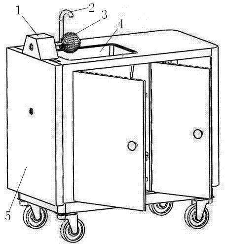
图1为本实用新型的立体图。 Fig. 1 is a perspective view of the utility model.
图2为本实用新型内部结构示意图。 Fig. 2 is a schematic diagram of the internal structure of the utility model.
图3为本实用新型的正面视图。 Fig. 3 is a front view of the utility model.
图4为本实用新型传动机构连接关系的零件示意图。 Fig. 4 is a schematic diagram of the components of the connection relationship of the transmission mechanism of the present invention.
图中:1上端盖、2出水龙头、3洗涤毛刷、4洗涤槽、5传动机构安装箱、6碗架、7惯性轮、8皮带、9传动皮带轮、10连杆、11脚踏板、12废水收集箱、13废水过滤桶、14踏板支架、15曲轴、16输出皮带轮、17集流板。 In the figure: 1 upper end cover, 2 outlet faucet, 3 washing brush, 4 washing tank, 5 transmission mechanism installation box, 6 bowl rack, 7 inertia wheel, 8 belt, 9 transmission pulley, 10 connecting rod, 11 pedal, 12 waste water collection box, 13 waste water filter barrel, 14 pedal bracket, 15 crankshaft, 16 output pulley, 17 collector plate.
具体实施方式 Detailed ways
下面结合附图,通过实施例对本实用新型作进一步地说明。 Below in conjunction with accompanying drawing, the utility model is further described by embodiment.
实施例: Example:
参见图1-图4,一种节能高效洗涤橱柜,包括柜体、台面、洗涤槽4、出水龙头2和碗架6;洗涤槽4位于柜体内的一侧,其下设有废水过滤桶13和废水收集箱12,三者通过管道连通;柜体内的另一侧设有二层碗架6,碗架的底部设有集流板17,集流板17倾斜向下连接至废水收集箱12;洗涤槽4一侧柜壁外壁上设有传动机构安装箱5,传动机构安装箱5内设有曲轴15和传动皮带轮9;洗涤槽4外侧台面上设有上端盖1,上端盖1内设有输出皮带轮16。
Referring to Fig. 1-Fig. 4, an energy-saving and high-efficiency washing cabinet includes a cabinet body, a countertop, a
废水收集箱12外侧的柜体底板上设有脚踏板11,脚踏板的顶端外侧设有连接板,连接板穿过柜体外壁位于传动机构安装箱5内,脚踏板通过轴销连接着连杆10的一端,连杆10的另一端连接着安装于传动机构安装箱5中部的曲轴15,曲轴15的一侧轴端上设有传动皮带轮9;传动皮带轮与安装于上端盖1内的输出皮带轮16相配合由皮带8连接,输出皮带轮16的中心轴一端部设有洗涤毛刷3,洗涤毛刷3水平位于洗涤槽4的上方。输出皮带轮的中心轴另一端部设有惯性轮7。洗涤橱柜的底面设有四个转向轮,使得洗涤橱柜整体可以移动。
A
采用曲柄摇杆机构原理(类似脚踏式缝纫机的工作原理),脚踏式驱动来驱动毛刷的旋转。踩踏脚踏板11做往复摆动,通过连杆10带动曲轴15旋转,从而带动传动皮带轮9转动,利用皮带8传动带动输出皮带轮16转动,从而使洗涤毛刷3转动完成洗涤工作。设计有惯性轮7,其作用是输出皮带轮16连续快速旋转同时,依靠惯性轮7的惯性作用不仅可以使传动机构避免死点,实现连续旋转,还能是工作过程更加省力。传动机构的传动比为5:1。
Using the principle of crank rocker mechanism (similar to the working principle of a pedal sewing machine), the pedal drive is used to drive the rotation of the brush. Step on
洗涤时将洗涤液均匀的洒到毛刷上,将餐具的里侧对准毛刷,脚同时踩动踏板,使毛刷旋转对餐具进行洗涤,根据餐具的油污程度合理用力,当餐具油污较多且较难清洗是,稍将餐具与毛刷见得接触力增大。洗涤毛刷3根据餐具的不同,毛刷的形式也不同,设计了不同类型的几种短轴毛刷。根据餐具的大小可选用不同类型的毛刷,洗涤毛刷与输出皮带轮16的输出轴采用螺栓固定的可拆式连接,便于毛刷的更换。毛刷转动可与餐具直接接触,操作方便,清洗效果好。省时省力。并可根据餐具的油污程度合理确定用水量,达到节约用水目的。
When washing, sprinkle the washing liquid evenly on the brush, align the inner side of the tableware with the brush, and step on the pedal at the same time to make the brush rotate to wash the tableware. Use reasonable force according to the degree of oil pollution of the tableware. If there are many and difficult to clean, the contact force between the tableware and the brush will increase slightly. Washing
Claims (3)
Priority Applications (1)
| Application Number | Priority Date | Filing Date | Title |
|---|---|---|---|
| CN201220178950XU CN202515025U (en) | 2012-04-25 | 2012-04-25 | Energy-saving high-efficiency washing cabinet |
Applications Claiming Priority (1)
| Application Number | Priority Date | Filing Date | Title |
|---|---|---|---|
| CN201220178950XU CN202515025U (en) | 2012-04-25 | 2012-04-25 | Energy-saving high-efficiency washing cabinet |
Publications (1)
| Publication Number | Publication Date |
|---|---|
| CN202515025U true CN202515025U (en) | 2012-11-07 |
Family
ID=47098007
Family Applications (1)
| Application Number | Title | Priority Date | Filing Date |
|---|---|---|---|
| CN201220178950XU Expired - Fee Related CN202515025U (en) | 2012-04-25 | 2012-04-25 | Energy-saving high-efficiency washing cabinet |
Country Status (1)
| Country | Link |
|---|---|
| CN (1) | CN202515025U (en) |
Cited By (1)
| Publication number | Priority date | Publication date | Assignee | Title |
|---|---|---|---|---|
| CN115804976A (en) * | 2021-09-14 | 2023-03-17 | 禹州市禹威过滤设备有限公司 | Automatic filtering cabinet |
-
2012
- 2012-04-25 CN CN201220178950XU patent/CN202515025U/en not_active Expired - Fee Related
Cited By (1)
| Publication number | Priority date | Publication date | Assignee | Title |
|---|---|---|---|---|
| CN115804976A (en) * | 2021-09-14 | 2023-03-17 | 禹州市禹威过滤设备有限公司 | Automatic filtering cabinet |
Similar Documents
| Publication | Publication Date | Title |
|---|---|---|
| CN101627893B (en) | Cleaning device | |
| CN204842304U (en) | Energy -conserving vegetable washing machine | |
| CN201481362U (en) | Clean device | |
| CN204722206U (en) | A kind of efficient fruit washer | |
| CN201189148Y (en) | Top brush type dishwasher | |
| CN202576921U (en) | Efficient manual washing machine | |
| CN201987507U (en) | Commercial lifting door type dish washer | |
| CN201234920Y (en) | Vegetable washing device by hand | |
| CN103610438B (en) | A kind of fully-automatic supersonic dish-washing machine | |
| CN221844229U (en) | A kitchen island with a countertop that is easy to clean | |
| CN204863039U (en) | Chopsticks machine is washed to family expenses | |
| CN200994760Y (en) | Efficient rolling-brush plate washer | |
| CN208527591U (en) | A kind of municipal garbage barrel cleaner structure | |
| CN105534450A (en) | Household automatic dish washing machine | |
| CN201271170Y (en) | Novel rice washer | |
| CN209048072U (en) | A kind of novel household chopsticks cleaning machine | |
| CN201205557Y (en) | Cleaning mechanism for keyboard washer | |
| CN201393992Y (en) | New water spray device for dishwasher | |
| CN206228302U (en) | Electric household cleaner | |
| CN204336854U (en) | Automatic mop cleaner | |
| CN211674110U (en) | Household dish washing machine capable of washing and brushing | |
| CN202559110U (en) | Washing machine attached with electric washing brush | |
| CN2593735Y (en) | Dish-washing machines | |
| CN205411119U (en) | Domestic automatic dish washing machine | |
| CN201831847U (en) | Dish washing machine |
Legal Events
| Date | Code | Title | Description |
|---|---|---|---|
| C14 | Grant of patent or utility model | ||
| GR01 | Patent grant | ||
| C17 | Cessation of patent right | ||
| CF01 | Termination of patent right due to non-payment of annual fee |
Granted publication date: 20121107 Termination date: 20130425 |