CN202506568U - Coating machine extrusion die gap adjustment mechanism - Google Patents
Coating machine extrusion die gap adjustment mechanism Download PDFInfo
- Publication number
- CN202506568U CN202506568U CN2012200493397U CN201220049339U CN202506568U CN 202506568 U CN202506568 U CN 202506568U CN 2012200493397 U CN2012200493397 U CN 2012200493397U CN 201220049339 U CN201220049339 U CN 201220049339U CN 202506568 U CN202506568 U CN 202506568U
- Authority
- CN
- China
- Prior art keywords
- bracket
- extrusion die
- die head
- fixed
- fixed bracket
- Prior art date
- Legal status (The legal status is an assumption and is not a legal conclusion. Google has not performed a legal analysis and makes no representation as to the accuracy of the status listed.)
- Expired - Fee Related
Links
- 238000001125 extrusion Methods 0.000 title claims abstract description 36
- 239000011248 coating agent Substances 0.000 title claims abstract description 13
- 238000000576 coating method Methods 0.000 title claims abstract description 13
- 230000000694 effects Effects 0.000 abstract description 7
- 239000002002 slurry Substances 0.000 abstract description 5
- 238000004519 manufacturing process Methods 0.000 abstract description 4
- 239000011149 active material Substances 0.000 description 4
- 238000000034 method Methods 0.000 description 4
- HBBGRARXTFLTSG-UHFFFAOYSA-N Lithium ion Chemical compound [Li+] HBBGRARXTFLTSG-UHFFFAOYSA-N 0.000 description 2
- 150000002500 ions Chemical group 0.000 description 2
- 229910001416 lithium ion Inorganic materials 0.000 description 2
- 238000004026 adhesive bonding Methods 0.000 description 1
- 230000009286 beneficial effect Effects 0.000 description 1
- 230000005540 biological transmission Effects 0.000 description 1
- 238000004891 communication Methods 0.000 description 1
- 230000007547 defect Effects 0.000 description 1
- 238000010586 diagram Methods 0.000 description 1
- 239000003792 electrolyte Substances 0.000 description 1
- 238000002347 injection Methods 0.000 description 1
- 239000007924 injection Substances 0.000 description 1
- 239000007788 liquid Substances 0.000 description 1
- 239000000463 material Substances 0.000 description 1
- 238000007789 sealing Methods 0.000 description 1
- 238000004513 sizing Methods 0.000 description 1
- 239000000243 solution Substances 0.000 description 1
- 230000007847 structural defect Effects 0.000 description 1
- 238000003466 welding Methods 0.000 description 1
Images


Classifications
-
- Y—GENERAL TAGGING OF NEW TECHNOLOGICAL DEVELOPMENTS; GENERAL TAGGING OF CROSS-SECTIONAL TECHNOLOGIES SPANNING OVER SEVERAL SECTIONS OF THE IPC; TECHNICAL SUBJECTS COVERED BY FORMER USPC CROSS-REFERENCE ART COLLECTIONS [XRACs] AND DIGESTS
- Y02—TECHNOLOGIES OR APPLICATIONS FOR MITIGATION OR ADAPTATION AGAINST CLIMATE CHANGE
- Y02E—REDUCTION OF GREENHOUSE GAS [GHG] EMISSIONS, RELATED TO ENERGY GENERATION, TRANSMISSION OR DISTRIBUTION
- Y02E60/00—Enabling technologies; Technologies with a potential or indirect contribution to GHG emissions mitigation
- Y02E60/10—Energy storage using batteries
Landscapes
- Coating Apparatus (AREA)
Abstract
本实用新型公开一种电池极片生产设备技术领域的涂布机挤压模头间隙调整机构,包括挤压模头、固定在机架上的固定支架、与所述固定支架横向滑动连接的移动支架、设置在所述固定支架上的驱动装置,所述驱动装置的输出端与所述移动支架连接,所述挤压模头设置在所述移动支架上。操作时,本实用新型通过所述驱动装置驱动所述移动支架于所述固定支架上滑动,以使所述移动支架上的挤压模头接触到带体,此时挤压模头中的浆料流出对带体进行涂浆,保证带体的涂浆效果,提高产品的合格率,有利于市场竞争。
The utility model discloses a gap adjustment mechanism for an extrusion die head of a coating machine in the technical field of battery electrode production equipment, comprising an extrusion die head, a fixed bracket fixed on a frame, a mobile bracket connected to the fixed bracket in a transverse sliding manner, and a driving device arranged on the fixed bracket, wherein the output end of the driving device is connected to the mobile bracket, and the extrusion die head is arranged on the mobile bracket. During operation, the utility model drives the mobile bracket to slide on the fixed bracket through the driving device, so that the extrusion die head on the mobile bracket contacts the belt body, at which time the slurry in the extrusion die head flows out to coat the belt body, thereby ensuring the coating effect of the belt body, improving the qualified rate of the product, and facilitating market competition.
Description
技术领域 technical field
本实用新型涉及电池极片生产设备技术领域,尤其涉及一种涂布机挤压模头间隙调整机构。The utility model relates to the technical field of battery pole piece production equipment, in particular to an extrusion die gap adjustment mechanism of a coating machine.
背景技术 Background technique
目前,以锂离子电池为代表的高能量密度的二次电池,正在日益成为手机、移动DVD、掌上电脑等通讯产品上重要的必不可少的电源配件。锂离子电池包括对之加以定型和保护的外壳体,外壳体之内的核心是由正、负电极芯体及电解液构成。而正、负电极芯体又包括集电体、涂布在集电体表面的活性物质层、电连接在集电体的预留空白区上的电极引脚和在正、负电极芯体之间的隔膜等,其中,活性物质层对于二次离子电池的充放电性能、电能容量等都具有决定性的作用。因此,生产实际中,必须将活性物质层按照设计的质量、密度等技术要求涂布在集电体表面上,而且要按照电池规格型号形成电池壳体内所盛装的小尺寸的极片,还要对这些小尺寸的极片进行卷绕形成电极芯体、然后在经过贴胶、压扁、装壳、盖板、焊接壳体、注液化成、压扁封口,最终制成成品电芯。由此可见,在集电体带上涂浆以生成活性物质层这一工艺在二次离子电池的生成过程中具有非常重要的作用。At present, high-energy-density secondary batteries represented by lithium-ion batteries are increasingly becoming important and indispensable power accessories for communication products such as mobile phones, mobile DVDs, and handheld computers. Lithium-ion batteries include an outer casing that is shaped and protected, and the core inside the outer casing is composed of positive and negative electrode cores and electrolyte. The positive and negative electrode cores include current collectors, the active material layer coated on the surface of the current collectors, the electrode pins electrically connected to the reserved blank areas of the current collectors, and the electrode pins between the positive and negative electrode cores. Among them, the active material layer plays a decisive role in the charge and discharge performance and electric energy capacity of the secondary ion battery. Therefore, in actual production, the active material layer must be coated on the surface of the current collector according to the technical requirements such as the quality and density of the design, and the small-sized pole pieces contained in the battery case must be formed according to the battery specifications and models. These small-sized pole pieces are wound to form an electrode core, and then after glueing, flattening, shelling, cover plate, welding shell, liquid injection, flattening and sealing, the finished battery core is finally made. It can be seen that the process of slurrying the current collector belt to form the active material layer plays a very important role in the production process of the secondary ion battery.
然而,在集电体带体上涂浆以生成极片的生成过程中,由于现有结构加工机械的缺陷,装置有涂浆的挤压模头在与带体进行接触时,很容易由于机械结构上的缺陷,挤压模头与带体接触不良或过分挤压带体,造成涂浆过程中不均匀或者漏涂,产品不合格的极片。However, in the process of generating pole pieces by applying slurry on the current collector belt, due to the defects of existing structural processing machinery, when the extrusion die with slurry is in contact with the belt, it is easy to Structural defects, poor contact between the extrusion die and the strip body or excessive extrusion of the strip body, resulting in uneven or missing coating during the grouting process, and unqualified pole pieces.
实用新型内容Utility model content
本实用新型的目的在于提供一种保证涂浆效果、提高产品合格率的涂布机挤压模头间隙调整机构。The purpose of the utility model is to provide a coating machine extrusion die gap adjustment mechanism which can ensure the grouting effect and improve the qualified rate of products.
为实现上述目的,本实用新型的技术方案为提供一种涂布机挤压模头间隙调整机构,包括挤压模头、固定在机架上的固定支架、与所述固定支架横向滑动连接的移动支架、设置在所述固定支架上的驱动装置,所述驱动装置的输出端与所述移动支架连接,所述挤压模头设置在所述移动支架上;操作时,所述驱动装置驱动所述移动支架于所述固定支架上滑动,以使所述移动支架上的挤压模头接触到带体,此时挤压模头中的浆料流出对带体进行涂浆,保证带体的涂浆效果。In order to achieve the above object, the technical solution of the present utility model is to provide a coating machine extrusion die gap adjustment mechanism, including extrusion die, a fixed bracket fixed on the frame, and a horizontal sliding connection with the fixed bracket. A moving bracket, a driving device arranged on the fixed bracket, the output end of the driving device is connected with the moving bracket, and the extrusion die is arranged on the moving bracket; during operation, the driving device drives The movable bracket slides on the fixed bracket, so that the extrusion die on the movable bracket contacts the belt body, at this time, the slurry in the extrusion die flows out to smear the belt body, ensuring that the belt body grouting effect.
较佳地,所述驱动装置为气缸。Preferably, the driving device is an air cylinder.
较佳地,所述固定支架与所述移动支架之间连接有微调装置,所述微调装置包括转动连接在所述固定支架上的丝杆、竖向滑动连接在所述固定支架上的限位斜块、设置在所述固定支架上的伺服电机,所述伺服电机的输出端驱动连接所述丝杆的一端,所述丝杆与所述限位斜块螺纹传动连接,所述限位斜块上设有可与所述移动支架顶推的斜面;进一步的,当所述挤压模头接触到带体时,所述伺服电机驱动丝杆转动,所述限位斜块在所述丝杆的螺纹传动下沿竖向上下移动,从而顶推所述移动支架横向滑动以实现所述挤压模头与所述带体的间隙处于最佳状态,使得带体的涂浆效果更好。Preferably, a fine-tuning device is connected between the fixed bracket and the mobile bracket, and the fine-tuning device includes a screw rod connected to the fixed bracket in rotation, a limit stop vertically slidably connected to the fixed bracket Inclined block, a servo motor arranged on the fixed bracket, the output end of the servo motor drives and connects one end of the screw rod, and the screw rod is connected to the limiting inclined block by screw transmission, and the limiting inclined block The block is provided with an inclined surface that can be pushed with the moving bracket; further, when the extrusion die touches the belt body, the servo motor drives the screw to rotate, and the limit inclined block The threaded drive of the rod moves vertically up and down, thereby pushing the moving bracket to slide laterally so as to realize that the gap between the extrusion die head and the belt body is in an optimal state, so that the grouting effect of the belt body is better.
较佳地,所述移动支架设有可与所述限位斜块的斜面顶触的顶柱;结构紧凑。Preferably, the mobile bracket is provided with a prop that can contact the inclined surface of the limiting inclined block; the structure is compact.
较佳地,所述顶柱上转动设有可与所述限位斜块的斜面顶触的转轮;利用所述转轮与所述斜面配合,使所述斜面不受磨损,保证了所述微调装置的使用寿命。Preferably, a running wheel that can contact the slope of the limiting inclined block is rotated on the top column; the running wheel is used to cooperate with the slope so that the slope is not worn, ensuring that the service life of the fine-tuning device described above.
与现有技术相比,本实用新型包括挤压模头、固定在机架上的固定支架、与所述固定支架横向滑动连接的移动支架、设置在所述固定支架上的驱动装置,所述驱动装置的输出端与所述移动支架连接,所述挤压模头设置在所述移动支架上。操作时,本实用新型通过所述驱动装置驱动所述移动支架于所述固定支架上滑动,以使所述移动支架上的挤压模头接触到带体,此时挤压模头中的浆料流出对带体进行涂浆,保证带体的涂浆效果,提高产品的合格率,有利于市场竞争。Compared with the prior art, the utility model includes an extrusion die head, a fixed bracket fixed on the frame, a movable bracket connected with the fixed bracket laterally slidably, and a driving device arranged on the fixed bracket. The output end of the driving device is connected with the moving support, and the extrusion die head is arranged on the moving support. During operation, the utility model drives the moving bracket to slide on the fixed bracket through the driving device, so that the extrusion die on the moving bracket touches the belt body, and at this time, the pulp in the extrusion die The material flows out to smear the belt body to ensure the sizing effect of the belt body, improve the pass rate of the product, and be conducive to market competition.
附图说明 Description of drawings
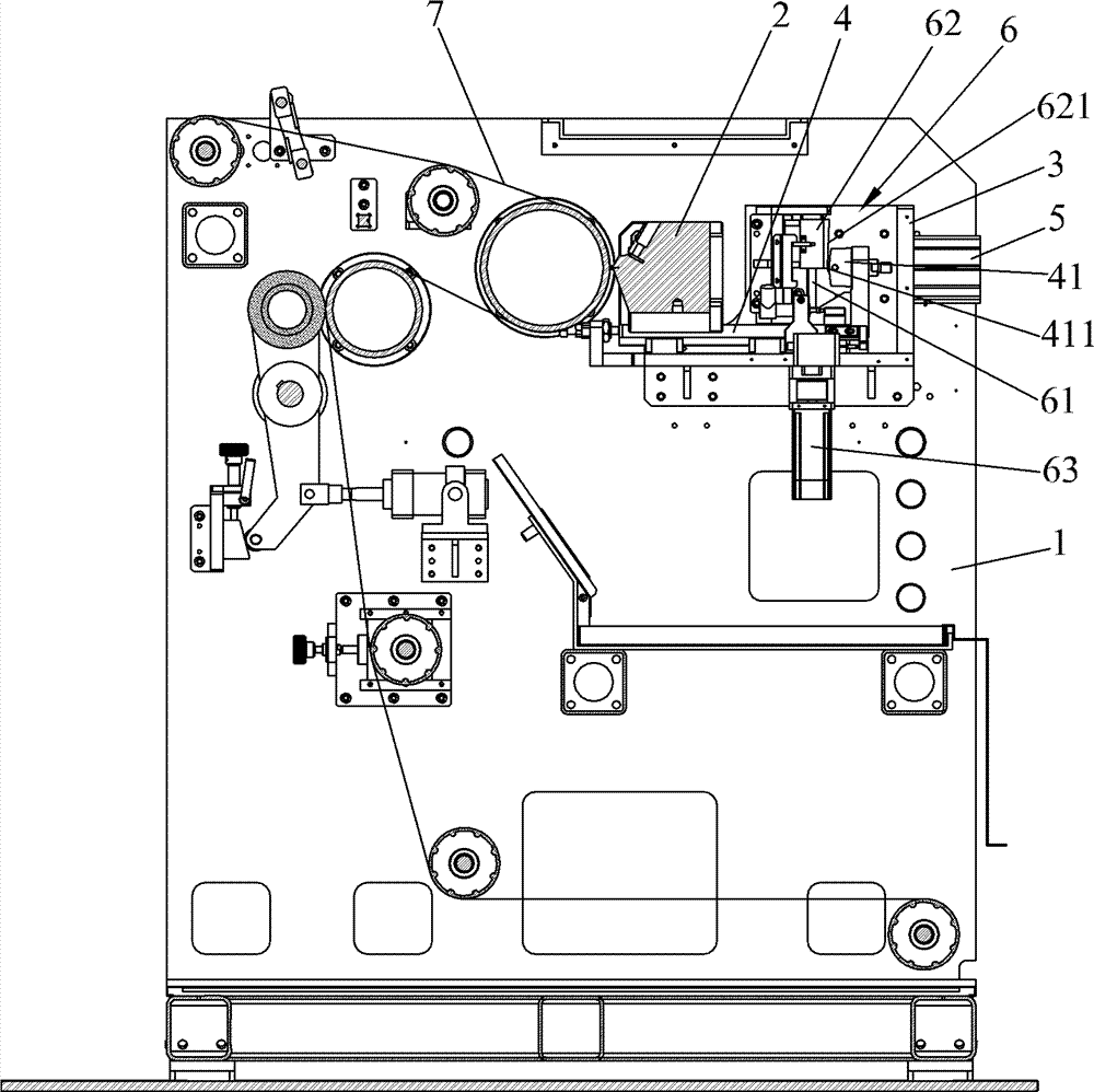
图1为本实用新型的结构示意图。Fig. 1 is the structural representation of the utility model.
图2为本实用新型的局部放大结构示意图。Fig. 2 is a schematic diagram of a partially enlarged structure of the present invention.
图3为本实用新型的使用状态视图。Fig. 3 is a use state view of the utility model.
具体实施方式 Detailed ways
下面结合附图和优选实施例对本实用新型作进一步说明。Below in conjunction with accompanying drawing and preferred embodiment the utility model is further described.
请参照图1~3所示,本实用新型提供的一种涂布机挤压模头2间隙调整机构,包括挤压模头2、固定支架3、移动支架4、驱动装置5,所述固定支架3固定在机架1上,所移动支架4横向滑动连接在所述固定支架3上,所述驱动装置5设置在所述固定支架3上的,所述驱动装置5的输出端与所述移动支架4连接,所述挤压模头2设置在所述移动支架4上。本实施例中,较佳地,所述驱动装置5为气缸。Please refer to Figures 1 to 3, a gap adjustment mechanism for the extrusion die
较佳地,所述固定支架3与所述移动支架4之间连接有微调装置6,所述微调装置6包括转动连接在所述固定支架3上的丝杆61、竖向滑动连接在所述固定支架3上的限位斜块62、设置在所述固定支架3上的伺服电机63,所述伺服电机63的输出端驱动连接所述丝杆61的一端,所述丝杆61与所述限位斜块62螺纹传动连接,所述限位斜块62上设有可与所述移动支架4顶推的斜面621,如此设计,当所述挤压模头2接触到带体7时,所述伺服电机63驱动丝杆61转动,所述限位斜块62在所述丝杆61的螺纹传动下沿竖向上下移动,从而顶推所述移动支架4轴向滑动以实现所述挤压模头2与所述带体7的间隙处于最佳状态,使得所述带体7的涂浆效果更好。Preferably, a fine-
较佳地,所述移动支架4设有可与所述限位斜块62的斜面621顶触的顶柱41,结构紧凑。Preferably, the
较佳地,所述顶柱41上转动设有可与所述限位斜块62的斜面621顶触的转轮411,利用所述转轮411与所述斜面621配合,使所述斜面621不受磨损,保证了所述微调装置6的使用寿命。Preferably, a
与现有技术相比,本实用新型通过于所述固定支架3上互动连接有移动支架4,设置在所述固定支架3上的驱动装置5与所述移动支架4连接,操作时,所述驱动装置5驱动所述移动支架4于所述固定支架3上滑动,以使所述移动支架4上的挤压模头2接触到带体7,此时挤压模头2中的浆料流出对带体7进行涂浆,保证带体7的涂浆效果,提高产品的合格率,有利于市场竞争。Compared with the prior art, the utility model is interactively connected with the
以上所揭露的仅为本实用新型的优选实施例而已,当然不能以此来限定本实用新型之权利范围,因此依本实用新型申请专利范围所作的等同变化,仍属本实用新型所涵盖的范围。What is disclosed above is only the preferred embodiment of the present utility model, and of course the scope of rights of the present utility model cannot be limited with this. Therefore, the equivalent changes made according to the patent scope of the utility model still belong to the scope covered by the utility model .
Claims (5)
Priority Applications (1)
| Application Number | Priority Date | Filing Date | Title |
|---|---|---|---|
| CN2012200493397U CN202506568U (en) | 2012-02-15 | 2012-02-15 | Coating machine extrusion die gap adjustment mechanism |
Applications Claiming Priority (1)
| Application Number | Priority Date | Filing Date | Title |
|---|---|---|---|
| CN2012200493397U CN202506568U (en) | 2012-02-15 | 2012-02-15 | Coating machine extrusion die gap adjustment mechanism |
Publications (1)
| Publication Number | Publication Date |
|---|---|
| CN202506568U true CN202506568U (en) | 2012-10-31 |
Family
ID=47059074
Family Applications (1)
| Application Number | Title | Priority Date | Filing Date |
|---|---|---|---|
| CN2012200493397U Expired - Fee Related CN202506568U (en) | 2012-02-15 | 2012-02-15 | Coating machine extrusion die gap adjustment mechanism |
Country Status (1)
| Country | Link |
|---|---|
| CN (1) | CN202506568U (en) |
Cited By (3)
| Publication number | Priority date | Publication date | Assignee | Title |
|---|---|---|---|---|
| CN108816645A (en) * | 2018-06-22 | 2018-11-16 | 东南大学 | Dynamic lithium battery base band squash type coating system |
| CN109433513A (en) * | 2019-01-11 | 2019-03-08 | 广东鑫瑞新材料科技有限公司 | A kind of device for precisely regulating of coating machine extrusion die lip and back rod gap |
| CN115999845A (en) * | 2022-12-30 | 2023-04-25 | 苏州擎动动力科技有限公司 | A gap coating device and a gap coating method |
-
2012
- 2012-02-15 CN CN2012200493397U patent/CN202506568U/en not_active Expired - Fee Related
Cited By (3)
| Publication number | Priority date | Publication date | Assignee | Title |
|---|---|---|---|---|
| CN108816645A (en) * | 2018-06-22 | 2018-11-16 | 东南大学 | Dynamic lithium battery base band squash type coating system |
| CN109433513A (en) * | 2019-01-11 | 2019-03-08 | 广东鑫瑞新材料科技有限公司 | A kind of device for precisely regulating of coating machine extrusion die lip and back rod gap |
| CN115999845A (en) * | 2022-12-30 | 2023-04-25 | 苏州擎动动力科技有限公司 | A gap coating device and a gap coating method |
Similar Documents
| Publication | Publication Date | Title |
|---|---|---|
| CN204122070U (en) | Flat die granulating machine | |
| CN203542278U (en) | Burr removal machine for positive electrodes and negative electrodes of lithium ion batteries | |
| CN204524381U (en) | A kind of battery tab cutting machine | |
| CN202079007U (en) | C roller scraper device of coater | |
| CN202495545U (en) | A mechanism for manufacturing winding layer gap | |
| CN203871432U (en) | Arc Li-polymer battery cell forming equipment | |
| CN203250821U (en) | Automatic pasting device for battery side edge adhesive tapes | |
| CN202513244U (en) | Flexible material constant tension system | |
| CN108033046A (en) | A kind of battery automatic packaging device | |
| CN207474602U (en) | A kind of cylindrical lithium battery cap sealing machine | |
| CN104319415A (en) | Cap assembly pneumatic press | |
| CN204424326U (en) | Spiral squeezing type cylindricality lithium ion battery | |
| CN202616337U (en) | Pole piece brush device of lithium battery automatic sheet-processing machine | |
| CN208835215U (en) | Lamination device is used in a kind of processing of lithium ion battery | |
| CN202921902U (en) | Lead sheath mould | |
| CN204156021U (en) | Block assembling aerostatic press | |
| CN205044200U (en) | Roller press | |
| CN213026223U (en) | A New Type of Cell Winding Structure | |
| CN202519352U (en) | Raw foil machine washing device | |
| CN215614302U (en) | Cylindrical lithium battery channeling machine roller head with elasticity | |
| CN206038819U (en) | Battery production needs car and cheats short circuit detection and integral type device that discharges | |
| CN208810260U (en) | A kind of lithium cell cathode material grinding device | |
| CN221851252U (en) | A lithium-ion battery negative electrode material compacting device | |
| CN208460914U (en) | A kind of ion battery packet energy-saving type high-temperature pressurization formation device | |
| CN100514738C (en) | Flattening device for battery roll |
Legal Events
| Date | Code | Title | Description |
|---|---|---|---|
| C14 | Grant of patent or utility model | ||
| GR01 | Patent grant | ||
| CF01 | Termination of patent right due to non-payment of annual fee | ||
| CF01 | Termination of patent right due to non-payment of annual fee |
Granted publication date: 20121031 Termination date: 20200215 |