CN202501173U - Multi-directional rotatable bracing frame - Google Patents
Multi-directional rotatable bracing frame Download PDFInfo
- Publication number
- CN202501173U CN202501173U CN2012200170742U CN201220017074U CN202501173U CN 202501173 U CN202501173 U CN 202501173U CN 2012200170742 U CN2012200170742 U CN 2012200170742U CN 201220017074 U CN201220017074 U CN 201220017074U CN 202501173 U CN202501173 U CN 202501173U
- Authority
- CN
- China
- Prior art keywords
- inverted
- saddle
- top plate
- shaped top
- top board
- Prior art date
- Legal status (The legal status is an assumption and is not a legal conclusion. Google has not performed a legal analysis and makes no representation as to the accuracy of the status listed.)
- Expired - Fee Related
Links
- 230000007704 transition Effects 0.000 claims description 4
- 238000009434 installation Methods 0.000 abstract description 11
- 230000009471 action Effects 0.000 description 3
- 230000008901 benefit Effects 0.000 description 3
- 230000005484 gravity Effects 0.000 description 3
- 238000000034 method Methods 0.000 description 3
- 230000008859 change Effects 0.000 description 2
- 230000036544 posture Effects 0.000 description 2
- 230000009286 beneficial effect Effects 0.000 description 1
- 238000006243 chemical reaction Methods 0.000 description 1
- 230000007812 deficiency Effects 0.000 description 1
- 238000010586 diagram Methods 0.000 description 1
- 230000000694 effects Effects 0.000 description 1
- 238000004519 manufacturing process Methods 0.000 description 1
- 238000012806 monitoring device Methods 0.000 description 1
- 230000008569 process Effects 0.000 description 1
- 238000003466 welding Methods 0.000 description 1
Images


Landscapes
- Snaps, Bayonet Connections, Set Pins, And Snap Rings (AREA)
Abstract
本实用新型涉及一种可多向旋转支撑架,其由倒U型顶板、鞍座、支脚、转动销轴、开口销构成,在倒U型顶板的顶面上有一个安装孔,在倒U型顶板的两侧面上对称制有纵向的长圆槽孔,在倒U型顶板的两侧面的底缘均制有左锁止槽及右锁止槽;鞍座上有一圆孔,鞍座的两侧面各焊接有一个限位销轴,鞍座通固定安装在支脚上部;倒U形顶板跨装在鞍座上,采用转动销轴穿过长圆槽孔及圆孔进行可转动式安装,转动销轴的另一端通过开口销固定,通过将限位销轴选择性与倒U型顶板两侧面底缘所制的左锁止槽或右锁止槽进行定位改变倒U型顶板顶面与鞍座的安装角度。本实用新型不仅能满足支撑位置调整的需要,又可以在极限位置保持稳定支撑状态。
The utility model relates to a multi-directional rotatable support frame, which is composed of an inverted U-shaped top plate, a saddle, a support foot, a rotating pin shaft, and a cotter pin. There is a mounting hole on the top surface of the inverted U-shaped top plate. The two sides of the top plate are symmetrically formed with longitudinal long circular slot holes, and the bottom edges of both sides of the inverted U-shaped top plate are formed with left locking grooves and right locking grooves; there is a round hole on the saddle, and the two sides of the saddle A limit pin is welded on each side, and the saddle is fixedly installed on the upper part of the leg; the inverted U-shaped top plate is straddled on the saddle, and the rotating pin passes through the long circular slot hole and the round hole for rotatable installation. The other end of the shaft is fixed by a cotter pin, and the upper surface of the inverted U-shaped top plate and the saddle can be changed by positioning the limit pin shaft selectively with the left locking groove or the right locking groove made on the bottom edge of both sides of the inverted U-shaped top plate the installation angle. The utility model can not only meet the requirement of adjusting the support position, but also can maintain a stable support state at the extreme position.
Description
技术领域 technical field
本实用新型涉及一种可多向旋转支撑架。 The utility model relates to a multidirectional rotatable support frame. the
背景技术 Background technique
多数产品在使用或安装时需要有底座或支撑架,而某些产品(如家用板式电散热器、监控装置等)有时需要多种支撑状态,即产品本体与支撑架之间的相对姿态不同。为满足该类产品对支撑状态多样、多变的需要,实际应用中采用结构较为复杂的支撑架来实现。这不但增加了产品的制造、使用成本,也在一定程度上增加了产品安装使用的复杂性。 Most products require a base or a support frame when used or installed, and some products (such as household panel electric radiators, monitoring devices, etc.) sometimes require multiple support states, that is, the relative postures between the product body and the support frame are different. In order to meet the needs of various and changeable support states for this type of products, a support frame with a relatively complex structure is used in practical applications. This not only increases the cost of manufacturing and using the product, but also increases the complexity of product installation and use to a certain extent. the
发明内容 Contents of the invention
本实用新型的目的在于克服现有技术的不足,提供一种结构巧妙、简单可靠、造价低、操作方便的可多向旋转并限位的支撑架。 The purpose of the utility model is to overcome the deficiencies of the prior art, and provide a multi-directional rotating and position-limiting support frame with ingenious structure, simple and reliable, low cost and convenient operation. the
本实用新型解决其技术问题是采用以下技术方案实现的: The utility model solves its technical problem and adopts the following technical solutions to realize:
一种可多向旋转并限位的支撑架,其特征在于:由倒U型顶板(1)、鞍座(2)、支脚(3)、转动销轴(4)、开口销(5)构成,在倒U型顶板(1)的顶面上有一个安装孔(1-1),在倒U型顶板(1)的两侧面上对称制有纵向的长圆槽孔(1-2),在倒U型顶板(1)的两侧面的底缘均制有左锁止槽(1-3)及右锁止槽(1-4);鞍座(2)上有一圆孔(2-1),鞍座的两侧面各焊接有一个限位销轴(2-2),鞍座(2)通固定安装在支脚(3)上部;倒U形顶板(1)跨装在鞍座(2)上,采用转动销轴(4)穿过长圆槽孔(1-2)及圆孔(2-1)进行可转动式安装,转动销轴的另一端通过开口销(5)固定,通过将限位销轴选择性与倒U型顶板两侧面底缘所制的左锁止槽(1-3)或右锁止槽(1-4)进行定位改变倒U型顶板顶面与鞍座的安装角度。 A support frame capable of multi-directional rotation and position limitation, characterized in that it is composed of an inverted U-shaped top plate (1), a saddle (2), a foot (3), a rotating pin shaft (4), and a cotter pin (5) , there is a mounting hole (1-1) on the top surface of the inverted U-shaped top plate (1), and longitudinal oblong slot holes (1-2) are symmetrically formed on both sides of the inverted U-shaped top plate (1). The bottom edges of the two sides of the inverted U-shaped top plate (1) are all shaped with left locking grooves (1-3) and right locking grooves (1-4); there is a round hole (2-1) on the saddle (2) , a limit pin (2-2) is welded on both sides of the saddle, and the saddle (2) is fixedly installed on the upper part of the foot (3); the inverted U-shaped top plate (1) straddles the saddle (2) Above, use the rotating pin shaft (4) to pass through the long circular slot hole (1-2) and the round hole (2-1) for rotatable installation, and the other end of the rotating pin shaft is fixed by the cotter pin (5). The position pin shaft is selectively positioned with the left locking groove (1-3) or the right locking groove (1-4) made on the bottom edge of both sides of the inverted U-shaped top plate to change the installation of the top surface of the inverted U-shaped top plate and the saddle angle. the
而且,在倒U型顶板的顶面上还制有辅助安装孔。 Moreover, auxiliary mounting holes are also formed on the top surface of the inverted U-shaped top plate. the
而且,在倒U型顶板(1)的两侧面的所制的左锁止槽(1-3)及右锁止槽(1-4)之间的底缘为圆弧过渡。 Moreover, the bottom edge between the left locking groove (1-3) and the right locking groove (1-4) formed on both sides of the inverted U-shaped top plate (1) is a circular arc transition. the
本实用新型的优点和有益效果为: Advantage and beneficial effect of the present utility model are:
本实用新型结构设计科学合理,将支撑架整体分为可相对活动的两部分,以长圆槽孔、锁止槽的巧妙结构为基础,利用转动销轴与限位销轴的位置的灵活变化,使两部分既可以相对运动,满足支撑位置调整的需要,又可以在极限位置保持稳定支撑状态。本实用新型还具有结构简单可靠、操作方便、成本低等优点。本实用新型还作为系列化产品单独生产销售,以满足小型物件(相对不超出本实用新型的结构所限的支撑重量)的立式或挂式支撑、或立式与挂式支撑可灵活转换的支撑要求。 The structure design of the utility model is scientific and reasonable, and the support frame is divided into two parts that can be relatively movable. The two parts can move relative to each other to meet the needs of adjusting the support position, and can also maintain a stable support state at the limit position. The utility model also has the advantages of simple and reliable structure, convenient operation and low cost. The utility model is also independently produced and sold as a serialized product to meet the vertical or hanging support of small objects (relatively not exceeding the support weight limited by the structure of the utility model), or the flexible conversion of vertical and hanging supports. support requirements. the
附图说明 Description of drawings
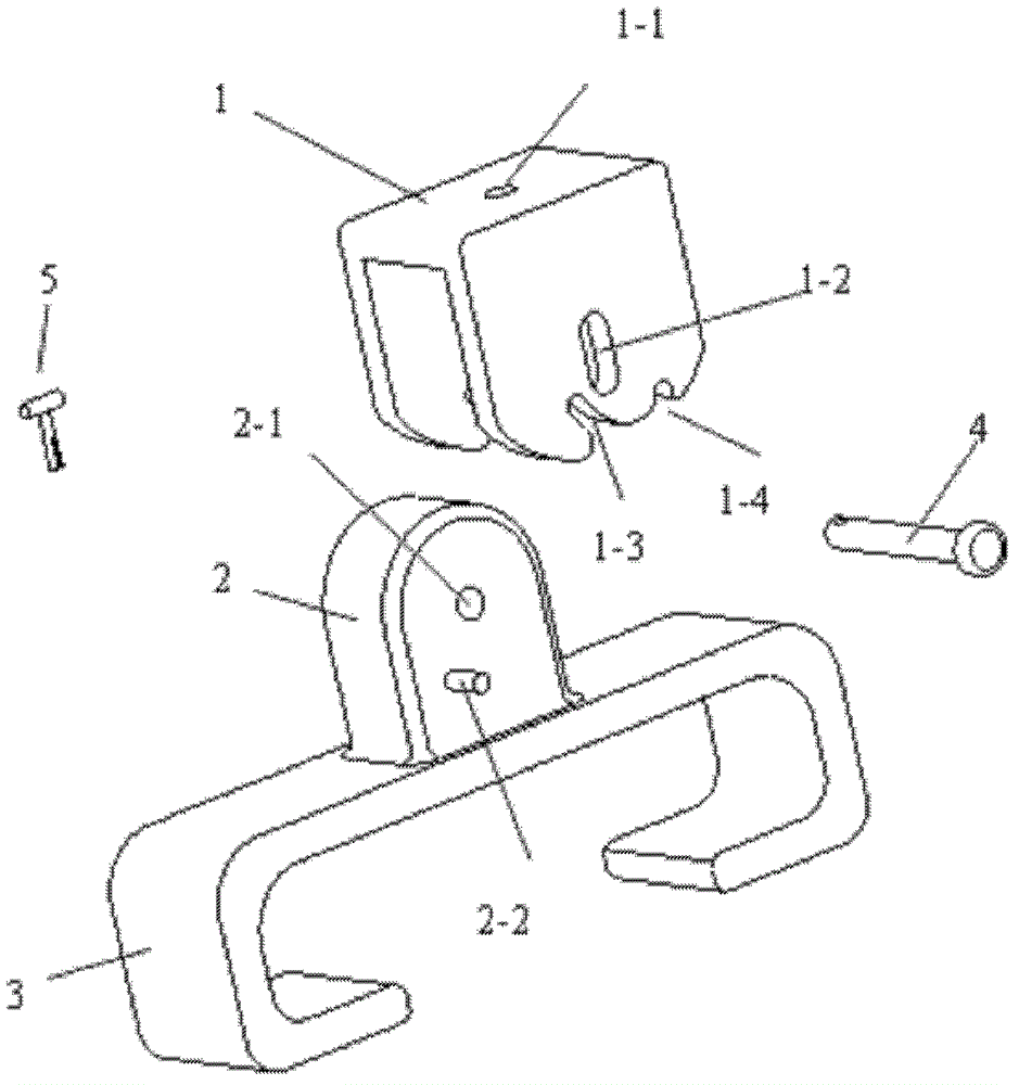
图1为本实用新型的立体结构爆炸图。 Fig. 1 is the exploded view of the three-dimensional structure of the utility model. the
图2为本实用新型的侧视结构爆炸图。 Figure 2 is an exploded view of the utility model in side view. the
图3为本实用新型的第一稳定支撑状态的前视图。 Fig. 3 is a front view of the first stable support state of the present invention. the
图4为本实用新型的第二稳定支撑状态的前视图。 Fig. 4 is a front view of the second stable support state of the present invention. the
图5为本实用新型的支撑状态转换过程示意图。 Fig. 5 is a schematic diagram of the transition process of the support state of the present invention. the
本实用新型可多向旋转并限位的支撑架附图中附图标记说明。 The supporting frame of the utility model that can rotate in multiple directions and limit the position is illustrated by reference numerals in the accompanying drawings. the
1-U型顶板 2-鞍座 3-支脚 4-转动销轴 5-开口销 1-U-shaped top plate 2-saddle 3-foot 4-rotating pin 5-cotter pin
1-1安装孔 1-2长圆槽孔 1-3左锁止槽 1-4右锁止槽 1-1 mounting hole 1-2 oblong slot hole 1-3 left lock slot 1-4 right lock slot
2-1圆孔 2-2限位销轴 2-1 round hole 2-2 limit pin shaft
具体实施方式 Detailed ways
下面结合附图对本实用新型可多向旋转并限位的支撑架作进一步详细说明。 The support frame capable of multi-directional rotation and position limitation of the present invention will be further described in detail below in conjunction with the accompanying drawings. the
如图1、2所示,一种可多向旋转并限位的支撑架,其由倒U型顶板(1)、鞍座(2)、支脚(3)、转动销轴(4)、开口销(5)构成。在倒U型顶板(1)的顶面上有一个安装孔(1-1),在倒U型顶板的顶面上还制有辅助安装孔。在倒U型顶板(1)的两侧面上对称制有纵向的长圆槽孔(1-2)。在倒U型顶板(1)的两侧面的底缘均制有左锁止槽(1-3)及右锁止槽(1-4),在倒U型顶板(1)的两侧面的所制的左锁止槽(1-3)及右锁止槽(1-4)之间的底缘为圆弧过渡。 As shown in Figures 1 and 2, a support frame that can rotate in multiple directions and limit the position is composed of an inverted U-shaped top plate (1), a saddle (2), a foot (3), a rotating pin (4), an opening Pin (5) constitutes. There is a mounting hole (1-1) on the top surface of the inverted U-shaped top plate (1), and auxiliary mounting holes are also formed on the top surface of the inverted U-shaped top plate. Longitudinal oblong slotted holes (1-2) are symmetrically shaped on both sides of the inverted U-shaped top plate (1). Left locking grooves (1-3) and right locking grooves (1-4) are all shaped on the bottom edges of both sides of the inverted U-shaped top board (1), and all of the two sides of the inverted U-shaped top board (1) The bottom edge between the left locking groove (1-3) and the right locking groove (1-4) is a circular arc transition. the
鞍座(2)上有一圆孔(2-1),圆孔起着支承转动销轴的作用,鞍座的两侧面各焊接有一个限位销轴(2-2),限位销轴的作用在于卡在倒U形顶板的锁止槽内,其特征在于可与锁止槽配合,起到限位与承力作用,形式可为与鞍座焊接在一起的销轴或经冲压、折弯形成的“柱状”突起。 There is a round hole (2-1) on the saddle (2), and the round hole plays the role of supporting the rotating pin shaft. A limit pin shaft (2-2) is respectively welded on both sides of the saddle. The function is to be stuck in the locking groove of the inverted U-shaped top plate. It is characterized in that it can cooperate with the locking groove to play the role of limit and force bearing. The form can be a pin welded with the saddle or punched, folded A "column" protrusion formed by a bend. the
鞍座(2)通过焊接或其它固定方式固定安装在支脚(3)上部。倒U形顶板(1)跨装在鞍座(2)上,采用转动销轴(4)穿过长圆槽孔(1-2)及圆孔(2-1)进行可转动式安装,转动销轴的另一端通过开口销(5)固定,通过将限位销轴选择性与倒U型顶板两侧面底缘所制的左锁止槽(1-3)或右锁止槽(1-4)进行定位改变倒U型顶板顶面与鞍座的安装角度。 The saddle (2) is fixedly installed on the upper part of the leg (3) by welding or other fixing means. The inverted U-shaped top plate (1) is straddled on the saddle (2), and the rotating pin shaft (4) is used to pass through the long circular slot hole (1-2) and the round hole (2-1) for rotatable installation. The other end of the shaft is fixed by the cotter pin (5), and the left locking groove (1-3) or the right locking groove (1-4 ) for positioning to change the installation angle between the top surface of the inverted U-shaped top plate and the saddle. the
本实用新型的安装方式为: The installation method of the utility model is:
21倒U型顶板(1)顶面为可安装小型物件带安装孔的平面,物件安装时,可使用转动销轴等零件将物件的底面与倒U型顶板的顶面连接起来,并使两者可相对转动,如不需要相对转动,可再自带安装孔的周围适宜位置现场加工辅助安装孔。借助开口销(5)将倒U型顶板(1)与鞍座(2)连接为一体,使两者可绕转动销轴转动或移动。倒U形顶板(1)跨装在鞍座(2)上,采用转动销轴(4)穿过长圆槽孔(1-2)及圆孔(2-1)进行可转动式安装,开口销(5可防止转动销轴脱落。通过倒U型顶板上的左锁止槽(1-3)或右锁止槽(1-4)、鞍座限位销轴(2-2)、转动销轴(4)三者的综合支撑,可使本支撑架灵活转动,并稳定在两个极限位置上。 21 Inverted U-shaped top plate (1) The top surface is a plane with mounting holes for installing small objects. When installing objects, parts such as rotating pins can be used to connect the bottom surface of the object with the top surface of the inverted U-shaped top plate, and make the two Those can be rotated relative to each other. If relative rotation is not required, auxiliary mounting holes can be processed on-site at suitable positions around the mounting holes. The inverted U-shaped top plate (1) and the saddle (2) are connected as a whole by means of cotter pins (5), so that the two can rotate or move around the rotating pin shaft. The inverted U-shaped top plate (1) is straddled on the saddle (2), and the rotating pin shaft (4) is used to pass through the long circular slot hole (1-2) and the round hole (2-1) for rotatable installation, and the cotter pin (5 can prevent the rotating pin from falling off. Through the left locking groove (1-3) or right locking groove (1-4) on the inverted U-shaped top plate, the saddle limit pin (2-2), and the rotating pin The comprehensive support of the three shafts (4) can make the support frame rotate flexibly and be stable at two extreme positions.
本实用新型的调整方式为: The adjustment mode of the present utility model is:
如图3所示,当倒U型顶板(1)与鞍座(2)均保持竖直状态时,在重力作用下,倒U型顶板的长圆槽孔(1-2)上端抵在转动销轴(4)上,此时鞍座两侧的限位销轴(2-2)处在顶板的左侧锁止槽(1-3)的顶端位置,受到转动销轴(4)及限位销轴(2-2)的综合作用,倒U型顶板(1)及所支撑物在无外力作用下不会摆动(由于加工因素所致的构件间隙所导致的轻微摆动除外),处在稳定的竖直状态。这种位置状态可用于物件的地面竖直支撑。 As shown in Figure 3, when the inverted U-shaped top plate (1) and the saddle (2) are kept vertical, under the action of gravity, the upper end of the oblong slot hole (1-2) of the inverted U-shaped top plate is against the rotating pin shaft (4), at this time the limit pins (2-2) on both sides of the saddle are at the top of the left locking groove (1-3) of the top plate, and are affected by the rotation pin (4) and the limit Due to the comprehensive effect of the pin shaft (2-2), the inverted U-shaped top plate (1) and its supports will not swing without external force (except for slight swing caused by component gaps caused by processing factors), and are in a stable position. vertical state. This positional state can be used for the ground vertical support of the object. the
如图4所示,当向下拉动支脚(3)时,转动销轴(4)沿着倒U型顶板的长圆槽孔(1-2)滑动倒其底端,同时鞍座上的限位销轴(2-2)亦脱离左锁止槽(1-3)的极限位置,进而可将倒U型顶板(1)与鞍座(2)相对转动90度,鞍座上的限位销轴(2-2)进入倒U型顶板(1)的右侧锁止槽(1-4)内,此时倒U顶板(1)的仍然处于竖直状态,而鞍座(2)与支脚(3)已相对于倒U形顶板(1)转动了90度,在重力作用下,转动销轴(4)再次抵在长圆槽孔(1-2)的顶端,因此在转动销轴(4)与限位销轴(2-2)及右锁止槽(1-4)的综合作用,倒U型顶板与所支撑物处在稳定的位置,无外力(重力除外)作用下不会摆动(由于加工因素所致的构件间隙所导致的轻微摆动除外)。在这种状态下,可将支脚的底部按需要加工安装孔,采用膨胀螺栓等构件(如图5中虚线所示意构件)使支脚挂在墙壁上,该支撑位置用于物件的墙 壁挂式安装。 As shown in Figure 4, when the leg (3) is pulled down, the rotating pin (4) slides down the bottom end of the long circular slot hole (1-2) of the inverted U-shaped top plate, and at the same time the limit on the saddle Bearing pin (2-2) also disengages from the limit position of left locking groove (1-3), and then the inverted U-shaped top plate (1) and saddle (2) can be rotated 90 degrees relative to each other, and the limit pin on the saddle The shaft (2-2) enters the right locking groove (1-4) of the inverted U-shaped top plate (1), at this time the inverted U-shaped top plate (1) is still in a vertical state, and the saddle (2) and the legs (3) has rotated 90 degrees relative to the inverted U-shaped top plate (1), and under the action of gravity, the rotating pin shaft (4) is against the top of the oblong slot hole (1-2) again, so the rotating pin shaft (4) ) and the limit pin shaft (2-2) and the right locking groove (1-4), the inverted U-shaped top plate and the support are in a stable position, and will not swing under the action of no external force (except gravity) (Except for slight wobble caused by component clearance due to processing factors). In this state, the bottom of the foot can be processed with mounting holes as required, and the foot can be hung on the wall by using expansion bolts and other components (as shown by the dotted line in Figure 5). This support position is used for wall-mounted installation of objects . the
本实用新型可用于小型物件的地面支撑或墙壁的悬挂支撑,或作为小型物件“立挂两用”支撑座使用。具有结构简单可靠、造价低、使用方便的优点,可较好满足某些物品在安装、使用过程中被支撑物(物品)与支承座的相对位姿要求能够灵活调整的需要。 The utility model can be used for the ground support of small objects or the hanging support of walls, or as a support base for small objects "dual-purpose for vertical hanging". It has the advantages of simple and reliable structure, low cost, and convenient use, and can better meet the needs of flexible adjustment of the relative posture requirements of the supported object (item) and the support seat during the installation and use of certain objects. the
Claims (3)
- One kind can multidirectional rotation supporting frame; It is characterized in that: constitute by inverted U top board (1), saddle (2), leg (3), rotating pin (4), cotter pin (5); A mounting hole (1-1) is arranged on the end face of inverted U top board (1); Symmetry is shaped on oval longitudinally slotted eye (1-2) on the bi-side of inverted U top board (1), and the root edge in the bi-side of inverted U top board (1) all is shaped on left lock groove (1-3) and right lock groove (1-4); One circular hole (2-1) is arranged on the saddle (2), and the bi-side of saddle respectively are welded with a spacing bearing pin (2-2), logical leg (3) top that is fixedly mounted on of saddle (2); Inverted U-shaped top board (1) straddles on the saddle (2); Employing rotating pin (4) passes oval slotted eye (1-2) and circular hole (2-1) is installed turnably; The other end of rotating pin is fixing through cotter pin (5), through spacing bearing pin selectivity and made left lock groove (1-3) or the right lock groove (1-4) of inverted U top board bi-side root edge are positioned the setting angle that changes inverted U top board end face and saddle.
- 2. according to claim 1 can multidirectional rotation supporting frame, it is characterized in that: on the end face of inverted U top board (1), also be shaped on auxiliary mounting hole.
- 3. according to claim 1 can multidirectional rotation supporting frame, it is characterized in that: at the made left lock groove (1-3) of the bi-side of inverted U top board (1) and the root edge between the right lock groove (1-4) is arc transition.
Priority Applications (1)
| Application Number | Priority Date | Filing Date | Title |
|---|---|---|---|
| CN2012200170742U CN202501173U (en) | 2012-01-16 | 2012-01-16 | Multi-directional rotatable bracing frame |
Applications Claiming Priority (1)
| Application Number | Priority Date | Filing Date | Title |
|---|---|---|---|
| CN2012200170742U CN202501173U (en) | 2012-01-16 | 2012-01-16 | Multi-directional rotatable bracing frame |
Publications (1)
| Publication Number | Publication Date |
|---|---|
| CN202501173U true CN202501173U (en) | 2012-10-24 |
Family
ID=47037787
Family Applications (1)
| Application Number | Title | Priority Date | Filing Date |
|---|---|---|---|
| CN2012200170742U Expired - Fee Related CN202501173U (en) | 2012-01-16 | 2012-01-16 | Multi-directional rotatable bracing frame |
Country Status (1)
| Country | Link |
|---|---|
| CN (1) | CN202501173U (en) |
Cited By (5)
| Publication number | Priority date | Publication date | Assignee | Title |
|---|---|---|---|---|
| CN103062601A (en) * | 2012-12-27 | 2013-04-24 | 宁波三星电气股份有限公司 | Electric power terminal bracket |
| CN103807573A (en) * | 2014-03-04 | 2014-05-21 | 太仓云联信息科技有限公司 | Air cylinder support |
| CN104963638A (en) * | 2015-07-03 | 2015-10-07 | 西南石油大学 | Novel supporting device for gas drilling sand draining pipe |
| CN107415981A (en) * | 2017-07-31 | 2017-12-01 | 中车南京浦镇车辆有限公司 | Suspension arrangement for railway vehicle brake flexible connecting member |
| CN109374675A (en) * | 2018-12-14 | 2019-02-22 | 安徽工业大学 | An experimental device for studying the heat transfer of a high-temperature plate (blank) for rapid cooling of nozzles arranged in a matrix |
-
2012
- 2012-01-16 CN CN2012200170742U patent/CN202501173U/en not_active Expired - Fee Related
Cited By (6)
| Publication number | Priority date | Publication date | Assignee | Title |
|---|---|---|---|---|
| CN103062601A (en) * | 2012-12-27 | 2013-04-24 | 宁波三星电气股份有限公司 | Electric power terminal bracket |
| CN103062601B (en) * | 2012-12-27 | 2015-06-10 | 宁波三星智能电气有限公司 | Electric power terminal bracket |
| CN103807573A (en) * | 2014-03-04 | 2014-05-21 | 太仓云联信息科技有限公司 | Air cylinder support |
| CN104963638A (en) * | 2015-07-03 | 2015-10-07 | 西南石油大学 | Novel supporting device for gas drilling sand draining pipe |
| CN107415981A (en) * | 2017-07-31 | 2017-12-01 | 中车南京浦镇车辆有限公司 | Suspension arrangement for railway vehicle brake flexible connecting member |
| CN109374675A (en) * | 2018-12-14 | 2019-02-22 | 安徽工业大学 | An experimental device for studying the heat transfer of a high-temperature plate (blank) for rapid cooling of nozzles arranged in a matrix |
Similar Documents
| Publication | Publication Date | Title |
|---|---|---|
| CN204647772U (en) | The rotatable multi-direction fixer support of wide-angle | |
| CN202525620U (en) | Wall seat | |
| CN203591912U (en) | Wall-attached type double-rod lifting rod | |
| CN203424561U (en) | Foldable wall-mounted notebook computer desk | |
| CN206421281U (en) | A plastic prototype of the back shell of a computer monitor | |
| CN203297863U (en) | Support of static state stirring heat exchanger for hot melt glue | |
| CN204576349U (en) | A kind of dismountable portable computer cooling stand | |
| CN204153412U (en) | Novel display stand rotary head | |
| CN203273237U (en) | Projector hanging bracket | |
| CN202179409U (en) | Wall surface hanging device with movable hook | |
| CN209705631U (en) | A kind of adjustable height folding rack | |
| CN203979825U (en) | Wall formula telescopic type Flat computer support frame | |
| CN105508820B (en) | Display bracket rotary head | |
| CN103010483A (en) | Two-DOF (Degrees of Freedom) test platform for micro aerial vehicle | |
| CN205375159U (en) | High degree of freedom pendulum -arm mechanism | |
| CN204901251U (en) | Display support | |
| CN206910140U (en) | Multifunctional crib | |
| CN206225524U (en) | A kind of rotation fixing type pull rod support for electrical tilt antenna | |
| CN204141166U (en) | A kind of Flat computer support frame | |
| CN206558107U (en) | Projection teaching aid board for oblique view drawing | |
| CN202150083U (en) | A CPU cooling bracket | |
| CN203825531U (en) | Computer display supporting rack | |
| CN204555266U (en) | A mounting bracket for a filter | |
| CN205903096U (en) | Can height -adjusting , crib of length, width | |
| CN204279208U (en) | A kind of vehicle-mounted folding shelf |
Legal Events
| Date | Code | Title | Description |
|---|---|---|---|
| C14 | Grant of patent or utility model | ||
| GR01 | Patent grant | ||
| CF01 | Termination of patent right due to non-payment of annual fee | ||
| CF01 | Termination of patent right due to non-payment of annual fee |
Granted publication date: 20121024 Termination date: 20130116 |