CN202474949U - Intelligence vehicle high-voltage distribution management unit for electric vehicle - Google Patents
Intelligence vehicle high-voltage distribution management unit for electric vehicle Download PDFInfo
- Publication number
- CN202474949U CN202474949U CN2012200863426U CN201220086342U CN202474949U CN 202474949 U CN202474949 U CN 202474949U CN 2012200863426 U CN2012200863426 U CN 2012200863426U CN 201220086342 U CN201220086342 U CN 201220086342U CN 202474949 U CN202474949 U CN 202474949U
- Authority
- CN
- China
- Prior art keywords
- voltage
- contactor
- battery pack
- tension
- vehicle
- Prior art date
- Legal status (The legal status is an assumption and is not a legal conclusion. Google has not performed a legal analysis and makes no representation as to the accuracy of the status listed.)
- Expired - Fee Related
Links
Images


Abstract
The utility model discloses an intelligence vehicle high-voltage distribution management unit for an electric vehicle. High-voltage power of the intelligence vehicle high-voltage distribution management unit is input by a positive pole of a power battery pack, the high-voltage power is connected to a pre-charge resistance (R) 1 through a high-voltage direct current (DC) contactor KM 2 normally open contact and then gets into the positive pole of a high-voltage circuit output port to externally connected high-voltage equipment, and a negative pole of the high-voltage circuit outlet is connected with the negative pole of the power battery pack. A high-voltage DC contactor KM 3 normally open contact is connected with a discharge R 2 in series and then is connected to the negative pole of the power battery pack and the back end of the high-voltage DC contactor KM 2 normally open contact in parallel, two ends of a high-voltage DC contactor KM 1 normally open contact are respectively connected with the positive pole input end of the power battery pack and the positive pole of the high-voltage circuit output port, and two ends of a high-voltage DC contactor KM 4 normally open contact are respectively connected with the input end of the power battery pack and the positive pole of a charger input port. A vehicle controller controls the open and close of the high-voltage DC contactor KM 1, KM 2, KM 3 and KM 4, and a power distribution unit (PDU) controller is connected with the vehicle controller and other outer equipment in line mode through a controller area network (CAN) 1.
Description
Technical field
The utility model relates to the intelligent vehicle-carried high voltage power distribution management system of a kind of used for electric vehicle.
Background technology
The new forms of energy commerial vehicle; Usually adopt the power memory module of electrokinetic cell a large amount of, in groups (like lithium ion battery) module like pure electronic, hybrid power, fuel cell etc. as vehicle; Be referred to as power battery module; And be driving motor supplies power source, thereby realize replacing the purpose of traditional vapour, diesel oil or fuel-economizing by power battery module.
On conventional truck; The main power supply that uses direct current 12V (for for the passenger car), direct current 24V low-tension supplies (supply voltage is less than direct current 60V) such as (for commercial car) as vehicle-mounted power consumption equipment; And possess comparatively perfect power distribution management and controlled function and module; Be referred to as car body controller (BCM:Body Control Module), realize the Artificial Control of low voltage equipment or control automatically, and possess corresponding safety control strategy.
In the new forms of energy vehicle, the voltage of electrokinetic cell is general, and especially in the commercial car field, voltage reaches as high as direct current 700V all greater than the safe voltage of 60V, and discharging current reaches as high as 400A.Therefore, safety, reasonable distribution and the control of the high voltage source of vehicle is become the emphasis of new forms of energy vehicle research.Simultaneously, some new-energy automobiles require to possess outer charge function, and need to add up, show the charge status of electric weight.During vehicle maintenance, need high voltage equipment is carried out maintenance operation, need possess the safety operation function.
At general new forms of energy vehicle, especially passenger car, the most basic Energy Chain should comprise: the electrokinetic cell unit, and energy management unit (PDU:Power Distribution Unit), main motor, electric machine controller, and other annexes etc.Referring to Fig. 1, wherein: heavy black line is represented high-pressure system, and the black fine rule is represented low-pressure system
The electrokinetic cell unit is as one of core component of electric automobile, and the output and the control of energy is mainly realized in the electrokinetic cell unit, and inner packet contains: battery battery core in groups (Battery), as the most basic energy-storage units; Battery management system slave plate (LECU:Local Electrical Control Unit) is realized the cell data acquisition; SOC (State Of Charger: estimation state-of-charge), heat management control etc. is realized in battery module managing unit (BMU:Battery Management Unit); Voltage transformer and current sensor are to the collection and the conversion output of output voltage, electric current, for battery management system provides data; Power distribution module (EDM:Electrical Distribution Module), the control of output contactor, precharge management; Battery balanced module (MBB:Monitor Balance Board) realizes the equilibrium between battery cell automatically.
Traditional energy management unit (PDU) is realized the distribution and the protection of energy; Mainly comprise: high voltage connector, fuse, high-tension connector etc.; Main distribution and the protection that realizes high voltage source; But because energy management unit (PDU) function is simple, therefore generally do not comprise controlled function, the control of the contactor that inside comprises is accomplished by entire car controller.Generally speaking, energy management unit (PDU) and entire car controller system are independently, and have mutually on the function and stress.
External commercial car state of the art is basic identical with the passenger car state of the art, and electrokinetic cell is a battery system in groups.But at home; Commercial car new forms of energy vehicle mainly applies to the passenger vehicle field at present, because the relation of continual mileage can be carried a plurality of independently electrokinetic cells unit usually; And adopt the function mode of changing power mode or extrapolation charging, change power mode or outer charge mode after promptly using up.Therefore, based on the consideration of reliability, fail safe and cost, functions such as the such complete control of similar passenger car, detection can't be realized, also there is no need to realize in employed each independent power battery unit inside on the commercial car.Therefore, its electrokinetic cell unit only comprises the most basic modules such as battery list core, battery management system slave plate LECU.And energy management unit PDU system comprises distribution and defencive function, the monitoring function of electric current, the vehicle body control unit functions such as (BCM unit) of high voltage source.Entire car controller has been born the safety detection function of the intrasystem control of PDU, transfer of data and electrokinetic cell.
But such design is overlapped control system often mutually independently more, and collaborative is poor; Versatility is not strong, is only applicable to specific vehicle, and needs entire car controller to reserve a large amount of control interface and control strategy; Cause the entire car controller burden serious, influence vehicle performance.
Present domestic related patent U.S. Patent No. has: Chinese patent 201020277614.1 discloses a kind of electric vehicle high voltage source control box; Mainly be applicable to passenger vehicle; The input and the output executing mechanism that only comprise high voltage source; Function is simple, does not comprise high voltage source safety system and intelligent control unit.Chinese patent 201110086132.2 discloses a kind of pure electronic commercial car high-tension distribution box; Though this distribution box is to pure electronic commercial car; But this patent also only comprises the input of high voltage source and the control system of output executing mechanism, insulating monitoring, energy demonstration and part etc., functions designs such as charging inlet, precharge and repid discharge outside on motor vehicle safety and basic function, also lacking; Also lack the high pressure interlock function, the high pressure interlock function has mandatory requirement in SAE J2344 " GUILDELINES FOR ELECTRIC VEHICLE SAFETY "; This patent also lacks the urgent design consideration of breaking off of high pressure etc.Therefore the use of this patent on pure electronic commercial car also exists more practical problem to need to solve.
The utility model content
The purpose of the utility model is to provide a kind of used for electric vehicle intelligent vehicle-carried high voltage power distribution administrative unit; This distribution management unit is incorporated into electrokinetic cell system built-in redundancy function in the PDU unit; And have outer charging inlet, precharge management and repid discharge management function, realize the modularization of PDU unit.
The utility model is achieved in that
The intelligent vehicle-carried high voltage power distribution administrative unit of a kind of used for electric vehicle comprises PDU controller, battery module managing unit B MU, electricity quantity display module, insulating monitoring system, resistance, HVDC contactor, voltage transformer WB1 and current sensor WB2;
High voltage source gets into the anodal external high-tension apparatus of high-tension circuit delivery outlet by the anodal input of power battery pack after HVDC contactor KM2 normally opened contact meets pre-charge resistance R1, high-tension circuit delivery outlet negative pole connects the power battery pack negative pole; Be attempted by the power battery pack negative pole behind the normally opened contact serial connection discharge resistance R2 of HVDC contactor KM3; And the rear end of HVDC contactor KM2 normally opened contact, said HVDC contactor KM2 normally opened contact rear end is the end points that HVDC contactor KM2 normally opened contact is serially connected with resistance R 1;
Normally opened contact two ends of HVDC contactor KM1 are connected on the power battery pack electrode input end respectively and the high-tension circuit delivery outlet is anodal; Normally opened contact two ends of HVDC contactor KM4 are connected on the power battery pack electrode input end respectively and external charge machine input port is anodal;
The switching of vehicle control unit controls HVDC contactor KM1, KM2, KM3 and KM4;
Said PDU controller input connects voltage transformer WB1 and current sensor WB2, and voltage transformer WB1 and current sensor WB2 are connected in power battery pack positive pole and negative input and the loop;
Said PDU controller connects entire car controller and other external equipment through the CAN1 line, and the PDU controller connects battery module managing unit B MU, insulating monitoring system and electricity quantity display module through the CAN1 line; Battery module managing unit B MU is through CAN2 external charging machine, and battery module managing unit B MU connects battery management system slave plate LECU through CAN3, realizes the cell data acquisition.
Said high voltage power distribution administrative unit connects dynamic power system input high voltage source through high-tension connector IL1, IL2, IL3, IL4; High-tension circuit output through high-tension connector IL5, IL6 ... ILn is connected to external high-tension apparatus; High-tension connector IL1, IL2 ... ILn forms interlocking loop; Interlocking loop connects entire car controller, and high-tension connector is used to detect the high-pressure system connection status.
The high voltage bus that said power battery pack is imported in the said administrative unit loop is connected to high pressure hand-operated service switch QS, and high pressure hand-operated service switch QS contains high-voltage fuse in inside.
The utility model is through being incorporated into electrokinetic cell system built-in redundancy function in the PDU unit; The PDU unit has outer charging inlet, precharge management and repid discharge management function; Realize modularization, intellectuality, flexibility and the safe of PDU unit, its standardization level is high; The high voltage source allocation manager and the security control function of new forms of energy vehicle can be realized in the PDU unit; And can carry out communication in real time with entire car controller; Can be applicable to the new forms of energy vehicle of number of different types through the function increase and decrease; Thereby realize the purpose of system flexibilityization, reduce the overlapping development of disparity items, adaptability is strong.
Description of drawings
Fig. 1 is existing new forms of energy vehicle Energy Chain configuration diagram;
The intelligent vehicle-carried high voltage power distribution administrative unit of Fig. 2 the utility model used for electric vehicle circuit diagram.
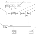
Fig. 3 is the intelligent vehicle-carried high voltage power distribution administrative unit of the used for electric vehicle of a utility model CAN network diagram.
Among the figure: 1 battery management system slave plate LECU, 2 battery module managing unit B MU, 3 insulating monitoring systems; The 4PDU controller; Fill machine (external charging machine), 6 entire car controllers, 7 miscellaneous equipments (other high-tension apparatus) outside 5; 8 electricity quantity display module (electric weight display unit), 9 power battery pack (electrical source of power).
Embodiment
Below in conjunction with accompanying drawing and specific embodiment the utility model is described further.
Referring to Fig. 2, Fig. 3; The intelligent vehicle-carried high voltage power distribution administrative unit of a kind of used for electric vehicle (hereinafter to be referred as the PDU unit) comprises PDU controller 4, battery module managing unit B MU 2, electricity quantity display module 8, insulating monitoring system 3, resistance R 1 and R2, HVDC contactor KM1, KM2, KM3 and KM4, voltage transformer WB1 and current sensor WB2.
High voltage source gets into the anodal external high-tension apparatus 7 of high-tension circuit delivery outlet by power battery pack 9 anodal inputs after HVDC contactor KM2 normally opened contact meets pre-charge resistance R1, high-tension circuit delivery outlet negative pole connects power battery pack 9 negative poles; Be attempted by power battery pack 9 negative poles behind the normally opened contact serial connection discharge resistance R2 of HVDC contactor KM3; And the rear end of HVDC contactor KM2 normally opened contact, said HVDC contactor KM2 normally opened contact rear end is the end points that HVDC contactor KM2 normally opened contact is serially connected with resistance R 1.
Normally opened contact two ends of HVDC contactor KM1 are connected on power battery pack 9 electrode input ends respectively and the high-tension circuit delivery outlet is anodal; Normally opened contact two ends of HVDC contactor KM4 are connected on power battery pack 9 electrode input ends respectively and external charge machine 5 input ports are anodal;
The switching of entire car controller 6 control HVDC contactor KM1, KM2, KM3 and KM4.
The intelligent vehicle-carried high voltage power distribution administrative unit of used for electric vehicle operation principle is:
At first, when system powers on: high voltage source is by power battery pack 9 anodal inputs, behind high pressure hand-operated service switch QS; To HVDC contactor KM2; This contactor receives entire car controller 6 instructions, connects its normally opened contact, gets into the anodal external main motor of high-tension circuit delivery outlet and other high-tension apparatuses 7 behind the high-tension current process pre-charge resistance R1; High-tension circuit delivery outlet negative pole connects power battery pack 9 negative poles, thereby accomplishes the precharge of main motor and other high-tension apparatuses 7.
After precharge was accomplished, HVDC contactor KM1 received entire car controller 6 instructions, connects its normally opened contact, high-tension current from power battery pack 9 positive poles through insure along separate routes FU2, FU3 ... FUn gets into each high-tension apparatus 7.At this moment, HVDC contactor KM2 outage recovers the normally open of its contact.But each high-tension apparatus 7 gets into operating state.
Secondly, when system cut-off, at first, HVDC contactor KM2 and KM1 receive entire car controller 6 instructions, and outage recovers the normally open of its contact.HVDC contactor KM3 receives entire car controller 6 instructions; Closed its normally opened contact; Make the positive pole of each high-tension apparatus 7 be connected on the high voltage source negative pole, constitute discharge loop through pre-charge resistance R1, HVDC contactor KM3 contact and discharge resistance R2.Resistance R 1, R2 consume residual electric energy in the high-tension apparatus 7 fast, make that the residual electric energy in the high-tension apparatus 7 quickly falls under the safe voltage.After about 5 seconds, HVDC contactor KM3 receives entire car controller 6 instructions, and outage recovers its contact normally open.The whole system outage is accomplished.
During charged state, entire car controller 6 control HVDC contactor KM1, KM2, KM3 are in off-position outside, and promptly the contact is in normally open.Entire car controller 6 is also controlled HVDC contactor KM4 energising; Its normally opened contact is closed; High-voltage power cathode is connected to the high-tension battery positive pole from charger 5 after through high-voltage fuse FU2, HVDC contactor KM4 closing contact, high pressure hand-operated service switch QS, and negative pole is connected to by outer charger 5 negative poles and carries out outer charging on the high-tension battery negative pole.After charging was accomplished, entire car controller 6 control HVDC contactor KM4 were in off-position, and normally open is recovered in the contact of HVDC contactor KM4.
In the intelligent vehicle-carried high voltage power distribution administrative unit of used for electric vehicle; Said PDU controller 4 inputs connect voltage transformer WB1 and current sensor WB2, and voltage transformer WB1 and current sensor WB2 are connected in power battery pack 9 positive poles and negative input and the loop;
Said current sensor WB2 is used for current acquisition; Can adopt the mode of shunt or Hall element; Through gathering the current data of bus or each branch, and through PDU controller 4 current data is sent to car load CAN network and supply driver and person skilled use.
Said voltage sensor WB1 is used for voltage acquisition, can adopt the mode of voltage transformer or voltage transmitter, through gathering the busbar voltage data, and through PDU controller 4 voltage data is sent to car load CAN network and supplies driver and person skilled use.
Said PDU controller 4 connects entire car controller 6 and other external equipment 7 through the CAN1 line, and PDU controller 4 connects battery module managing unit B MU 2, insulating monitoring system 3 and electricity quantity display module 8 through the CAN1 line; Battery module managing unit B MU 2 is through CAN2 external charging machine 5, and battery module managing unit B MU 2 connects battery management system slave plate LECU 1 through CAN3, realizes the cell data acquisition.
Said high voltage power distribution administrative unit (being the PDU unit) connects electrical source of power 9 systems input high voltage source through high-tension connector IL1, IL2, IL3, IL4; High-tension circuit output is through high-tension connector IL5, IL6 ... ILn is connected to external high-tension apparatus 7; High-tension connector IL1, IL2 ... ILn possesses the high pressure interlock function; Interlocking loop one end is connected to entire car controller 6, is used to detect the high-pressure system connection status.
Said high-tension connector IL1, IL2 ... ILn is used to connect high-pressure system, possesses the high pressure interlock function, is used to detect the high-pressure system connection status.When high-tension connector is extracted; Low pressure detects the loop and at first cuts off, and sends the signal that cuts off to entire car controller 6, and entire car controller 6 cuts off the coil power supply of corresponding HVDC contactor according to control strategy; Thereby personnel's safety is guaranteed in the output of cutoff high power supply.When high-tension connector inserts; At first connect high tension loop, the high tension loop of this moment is not because the existence of high pressure interlocking has high-tension electricity, after the high tension loop of high-tension connector fully contacts; Low pressure detects the loop and just can be switched on; And sending connection signal to entire car controller 6, entire car controller 6 is connected the coil power supply of corresponding HVDC contactor according to control strategy, thereby realizes the output of high voltage source.
High voltage bus in the said administrative unit of the said power battery pack 9 inputs loop, high voltage bus is connected to high pressure hand-operated service switch QS.High pressure hand-operated service switch QS is used to realize the hand off high voltage functionality; Be that high voltage bus master insurance and manual service switch set are one; To realize integrated purpose; And possess high pressure interlocking interface, can interface be connected in series in the high pressure interlocking loop of car load, realize the function of high pressure interlocking.When high pressure hand-operated service switch QS extracts, can together extract leading insurance, carry with the maintenance personal, prevent that other staff's mistake from powering on, thereby protect the maintenance personal of vehicle to the full extent.
The intelligent vehicle-carried high voltage power distribution administrative unit of the utility model used for electric vehicle control principle is following:
At first; High voltage source is by power battery pack 9 anodal inputs, and high-voltage fuse FU0 is contained in these power battery pack 9 inside, and it is inner to be connected to the PDU unit through high-tension connector IL3, the IL4 that has high pressure interlocking interface; The inner copper bar that uses forms high voltage bus in the PDU unit.High voltage bus is through high pressure hand-operated service switch QS, and high pressure hand-operated service switch QS contains the high tension loop main fuse, distributes to high pressure major loop and outer charge circuit.
Said high pressure major loop is made up of HVDC contactor group KM1, KM2, KM3 and KM4, high-voltage fuse group FU3, FU4, FU5, FU6-8, FU9, FUn, high-power noninductive resistance R1, R2 and high-tension connector IL1, IL2, IL3, IL4, IL5~IL8 and ILn.When the electric automobile execution powers on flow process; Entire car controller 6 judges through the CAN network whether inner each sub-systems in PDU unit is in normal operating state; Then through low-voltage interface output low-tension supply; Its normally opened contact of control HVDC contactor KM2 adhesive, high-voltage DC power supply carries out precharge operation through fuse FU1 to pre-charge resistance R1; After precharge was accomplished, entire car controller 6 was controlled its normally opened contact of HVDC contactor KM1 adhesive through low-voltage interface output low-tension supply, and HVDC contactor KM2 breaks off, and high voltage source is to whole high pressure main circuit power supply.Thereby accomplish the flow process that powers on.
After powering on, high voltage source is through the contact of HVDC contactor KM1, through the distribution of copper bar, and exports to different high pressure power consumption equipments 7 through high-voltage fuse group FU3, FU4~FUn protection.In the whole service process, entire car controller 6 is gathered each contacts of contactor signal with PDU controller 4, compares with control command, thereby judges whether in proper working order.If just can think HVDC contactor KM1 malfunction when the control command of HVDC contactor KM1 and state feedback signal do not meet, entire car controller 6 sends fault-signal through the CAN1 network, to alarm driver.
When vehicle need cut off the power supply; Entire car controller 6 control HVDC contactor KM1 and KM2 cut off the power supply simultaneously; HVDC contactor KM3 energising, its normally opened contact of adhesive is closed, thereby the residual amount of energy in the high pressure primary heat transport system is consumed through high-power resistance R1, R2; Guarantee that residual voltage dropped to below the 36V safe voltage in the high pressure primary heat transport system in 5 seconds, guarantee people's safety.After discharge was accomplished, HVDC contactor KM3 also broke off.Whole system is in off-position.
Outer charge circuit be by HVDC contactor KM4 control output; The control of this HVDC contactor KM4 charging confirmation signal on the charging inlet outside entire car controller 6 is built-in through collection PDU unit is controlled output; After outer charging inlet connects external charging device 5; Entire car controller 6 collects the charging confirmation signal; Break off HVDC contactor KM1, precharge HVDC contactor KM2 and HVDC contactor KM3 according to the control strategy program, the closed simultaneously outer HVDC contactor KM4 that charges, thus connect outer charge circuit.Charge to the vehicle mounted dynamic battery group by external charging device 5.After charging is accomplished; At first break off low-voltage control signal----charging confirmation signal, when entire car controller 6 receives the disconnection of charging confirmation signal, at first cut off the HVDC contactor KM4 of outer charging; And then according to control strategy, the closure of confirming HVDC contactor KM1 whether.
Outer charging inlet possesses CAN network communication function, and carries out CAN communication with battery management unit BMU 2 through the CAN2 line in inside, PDU unit, the monitoring charging current, and related datas such as charging voltage realize intelligent charge.When charging takes place unusually, battery management unit BMU 2 passes to PDU controller 4 through the CAN network with fault message through the CAN1 line, and PDU controller 4 sends warning message to entire car controller 6 again through the CAN1 line, and entire car controller 6 is taked corresponding operating according to control strategy.
In the CAN network; CAN1 represents the car load network; The node of its network mainly comprises: PDU controller 4; External equipment 7 (comprising motor, instrument etc.), the CAN1 line also connects PDU unit internal subnet network, and its network node mainly comprises: battery module managing unit B MU 2, insulating monitoring system 3 and PDU controller 4.CAN2 is outer charging sub-network, and CAN3 is the inside battery sub-network, and this two child network belongs to two separate networks of battery system.
Also comprise insulating monitoring system 3 in inside, PDU unit, be used to implement, and Monitoring Data is sent in the car load CAN network through the CAN1 line, and on instrument, show through PDU controller 4 to the monitoring of the insulation resistance between car load high-pressure system and vehicle body.When the situation that the insulation reduction takes place takes place; PDU controller 4 receives insulating monitoring system 3 through the alarm signal that the CAN1 line sends from the CAN network, make a copy for to entire car controller 6, and entire car controller 6 passes through corresponding control strategies; Cut off the coil power supply of corresponding HVDC contactor; Thereby the output of cutoff high power supply, and notify human pilot, guarantee personnel's safety.When insulation recovery just often, connect the output of corresponding high voltage source again through restarting the vehicle mode.
The PDU controller unit mainly is made up of PDU controller 4, voltage transformer WB1, current sensor WB2 and electric weight display unit 8, and judges that with the status signal of outer charging HVDC contactor KM4 car load is in discharge condition and still is in outer charged state through gathering HVDC contactor KM1.And on electric weight display unit 8, demonstrate system's current state; Information such as voltage and current data together with gathering send in the car load network through the CAN network; Mainly be on instrument, to show; And the system failure and warning message sent to entire car controller 6, judge system modes, safe class by entire car controller 6, thereby confirm corresponding operation.PDU controller 4 also can be carried out the control of HVDC contactor KM1, KM2, KM3 and KM4 by PDU controller 4, but the instruction on the control strategy is still sent by entire car controller 6.
In order to ensure system maintenance safety and emergency safety, the PDU unit of the utility model also need be equipped with high pressure hand-operated service switch QS, and the low-voltage interface of emergency switch.When vehicle was in service mode, the maintenance personal can extract manual service switch QS, and can carry with the maintenance personal, prevented that other staff's mistake from powering on, thereby protected maintenance personal's trouble free service of vehicle to the full extent, also was convenient to the replacing of car insurance.When vehicle generation emergency, like fire, fortuitous events such as collision, human pilot can pass through to cut off the emergency switch of front part of vehicle, thereby cuts off the power supply of vehicle high voltage connector, makes high-pressure system cut off the power supply.Thereby protect the driving safety of vehicle to the full extent.
More than be merely the preferred embodiment of the utility model; It is not the protection range that is used to limit utility model; Therefore, any modification of being done within all spirit and principles at the utility model, be equal to replacement, improvement etc., all be included within the protection range of the utility model.
Claims (3)
1. the intelligent vehicle-carried high voltage power distribution administrative unit of used for electric vehicle is characterized in that: comprise PDU controller, battery module managing unit B MU, electricity quantity display module, insulating monitoring system, resistance, HVDC contactor, voltage transformer WB1 and current sensor WB2;
High voltage source gets into the anodal external high-tension apparatus of high-tension circuit delivery outlet by the anodal input of power battery pack after HVDC contactor KM2 normally opened contact meets pre-charge resistance R1, high-tension circuit delivery outlet negative pole connects the power battery pack negative pole; Be attempted by the power battery pack negative pole behind the normally opened contact serial connection discharge resistance R2 of HVDC contactor KM3; And the rear end of HVDC contactor KM2 normally opened contact, said HVDC contactor KM2 normally opened contact rear end is the end points that HVDC contactor KM2 normally opened contact is serially connected with resistance R 1;
Normally opened contact two ends of HVDC contactor KM1 are connected on the power battery pack electrode input end respectively and the high-tension circuit delivery outlet is anodal; Normally opened contact two ends of HVDC contactor KM4 are connected on the power battery pack electrode input end respectively and external charge machine input port is anodal;
The switching of vehicle control unit controls HVDC contactor KM1, KM2, KM3 and KM4;
Said PDU controller input connects voltage transformer WB1 and current sensor WB2, and voltage transformer WB1 and current sensor WB2 are connected in power battery pack positive pole and negative input and the loop;
Said PDU controller connects entire car controller and other external equipment through the CAN1 line, and the PDU controller connects battery module managing unit B MU, insulating monitoring system and electricity quantity display module through the CAN1 line; Battery module managing unit B MU is through CAN2 external charging machine, and battery module managing unit B MU connects battery management system slave plate LECU through CAN3, realizes the cell data acquisition.
2. the intelligent vehicle-carried high voltage power distribution administrative unit of used for electric vehicle according to claim 1; It is characterized in that: said high voltage power distribution administrative unit connects dynamic power system input high voltage source through high-tension connector IL1, IL2, IL3, IL4; High-tension circuit output through high-tension connector IL5, IL6 ... ILn is connected to external high-tension apparatus; High-tension connector IL1, IL2 ... ILn forms interlocking loop; Interlocking loop connects entire car controller, and high-tension connector is used to detect the high-pressure system connection status.
3. the intelligent vehicle-carried high voltage power distribution administrative unit of used for electric vehicle according to claim 1; It is characterized in that: the high voltage bus that said power battery pack is imported in the said administrative unit loop is connected to high pressure hand-operated service switch QS, and high pressure hand-operated service switch QS contains high-voltage fuse in inside.
Priority Applications (1)
| Application Number | Priority Date | Filing Date | Title |
|---|---|---|---|
| CN2012200863426U CN202474949U (en) | 2012-03-09 | 2012-03-09 | Intelligence vehicle high-voltage distribution management unit for electric vehicle |
Applications Claiming Priority (1)
| Application Number | Priority Date | Filing Date | Title |
|---|---|---|---|
| CN2012200863426U CN202474949U (en) | 2012-03-09 | 2012-03-09 | Intelligence vehicle high-voltage distribution management unit for electric vehicle |
Publications (1)
| Publication Number | Publication Date |
|---|---|
| CN202474949U true CN202474949U (en) | 2012-10-03 |
Family
ID=46923076
Family Applications (1)
| Application Number | Title | Priority Date | Filing Date |
|---|---|---|---|
| CN2012200863426U Expired - Fee Related CN202474949U (en) | 2012-03-09 | 2012-03-09 | Intelligence vehicle high-voltage distribution management unit for electric vehicle |
Country Status (1)
| Country | Link |
|---|---|
| CN (1) | CN202474949U (en) |
Cited By (7)
| Publication number | Priority date | Publication date | Assignee | Title |
|---|---|---|---|---|
| CN102916354A (en) * | 2012-10-10 | 2013-02-06 | 潍柴动力股份有限公司 | High-tension distribution box for electric vehicle |
| CN102951025A (en) * | 2012-11-22 | 2013-03-06 | 东南(福建)汽车工业有限公司 | Automatic defense device for electric vehicle |
| CN102951026A (en) * | 2012-11-22 | 2013-03-06 | 东南(福建)汽车工业有限公司 | Charging and travelling interlocking device for electric automobile |
| CN103078357A (en) * | 2012-03-09 | 2013-05-01 | 柴冬燕 | Intelligent vehicle-mounted high-voltage power distribution management unit for electric vehicle |
| CN103532200A (en) * | 2013-10-25 | 2014-01-22 | 重庆五洲龙新能源汽车有限公司 | Battery management system of new energy automobile |
| CN104184191A (en) * | 2014-08-21 | 2014-12-03 | 广州益维电动汽车有限公司 | Whole vehicle control device and control method for electric vehicle |
| CN106379188A (en) * | 2016-09-30 | 2017-02-08 | 华南理工大学 | Energy management system for power battery of electric automobile and safety protection method |
-
2012
- 2012-03-09 CN CN2012200863426U patent/CN202474949U/en not_active Expired - Fee Related
Cited By (10)
| Publication number | Priority date | Publication date | Assignee | Title |
|---|---|---|---|---|
| CN103078357A (en) * | 2012-03-09 | 2013-05-01 | 柴冬燕 | Intelligent vehicle-mounted high-voltage power distribution management unit for electric vehicle |
| CN103078357B (en) * | 2012-03-09 | 2014-12-31 | 柴冬燕 | Intelligent vehicle-mounted high-voltage power distribution management unit for electric vehicle |
| CN102916354A (en) * | 2012-10-10 | 2013-02-06 | 潍柴动力股份有限公司 | High-tension distribution box for electric vehicle |
| CN102951025A (en) * | 2012-11-22 | 2013-03-06 | 东南(福建)汽车工业有限公司 | Automatic defense device for electric vehicle |
| CN102951026A (en) * | 2012-11-22 | 2013-03-06 | 东南(福建)汽车工业有限公司 | Charging and travelling interlocking device for electric automobile |
| CN103532200A (en) * | 2013-10-25 | 2014-01-22 | 重庆五洲龙新能源汽车有限公司 | Battery management system of new energy automobile |
| CN103532200B (en) * | 2013-10-25 | 2016-04-13 | 重庆五洲龙新能源汽车有限公司 | A kind of battery management system of new-energy automobile |
| CN104184191A (en) * | 2014-08-21 | 2014-12-03 | 广州益维电动汽车有限公司 | Whole vehicle control device and control method for electric vehicle |
| CN104184191B (en) * | 2014-08-21 | 2016-11-02 | 广州益维电动汽车有限公司 | A kind of electric automobile whole controls device and control method thereof |
| CN106379188A (en) * | 2016-09-30 | 2017-02-08 | 华南理工大学 | Energy management system for power battery of electric automobile and safety protection method |
Similar Documents
| Publication | Publication Date | Title |
|---|---|---|
| CN103078357B (en) | Intelligent vehicle-mounted high-voltage power distribution management unit for electric vehicle | |
| CN202474949U (en) | Intelligence vehicle high-voltage distribution management unit for electric vehicle | |
| CN108162989B (en) | Traction-assisted integrated vehicle-mounted energy storage system for urban rail transit vehicle | |
| CN109120055B (en) | Emergency traction and auxiliary storage battery system for rail transit | |
| CN203250832U (en) | Intelligent power battery quick change system for electric vehicle | |
| CN106253314A (en) | Communication base station ferric phosphate lithium cell echelon utilizes charge-discharge system and control method | |
| CN101722859A (en) | High-voltage safety system of hybrid electric vehicle | |
| CN206106977U (en) | Electric automobile power battery energy management system | |
| CN110605986B (en) | Off-grid mobile quick charging system and management method thereof | |
| CN111717052A (en) | Common-bus multifunctional mobile energy storage vehicle and control strategy | |
| CN106026306A (en) | New energy vehicle charging dynamic response system | |
| CN208867977U (en) | The commercial automobile-used high-voltage electric device of new energy | |
| CN106671814A (en) | Active safety protection system for power battery pack of electric automobile | |
| CN212400923U (en) | Netless self-walking energy storage and bidirectional AC/DC converter system for rail transit | |
| CN109120056A (en) | A kind of rail traffic standard EMU booster battery and case system | |
| CN102975628B (en) | High-voltage control system of electric automobile | |
| CN109703397A (en) | Multifunctional mobile power supply vehicle of meet an emergency based on power battery energy storage | |
| CN203596651U (en) | Low-voltage power supply interlocking circuit of electric vehicle | |
| CN208835826U (en) | A kind of rail traffic emergency traction and booster battery system | |
| CN205407350U (en) | Lithium ion battery electric power and for communication DC power supply system | |
| CN111591148A (en) | Netless self-walking energy storage and bidirectional AC/DC converter system for rail transit | |
| CN208939651U (en) | A kind of rail traffic standard EMU booster battery and case system | |
| CN217607526U (en) | Power battery charging switching system and power vehicle | |
| CN116080447A (en) | Energy storage type charging pile | |
| CN212400919U (en) | Non-net self-walking auxiliary storage battery energy storage system for rail transit |
Legal Events
| Date | Code | Title | Description |
|---|---|---|---|
| C14 | Grant of patent or utility model | ||
| GR01 | Patent grant | ||
| CF01 | Termination of patent right due to non-payment of annual fee |
Granted publication date: 20121003 Termination date: 20150309 |
|
| EXPY | Termination of patent right or utility model |