CN202474337U - Electrical connector assembly - Google Patents
Electrical connector assembly Download PDFInfo
- Publication number
- CN202474337U CN202474337U CN 201120559056 CN201120559056U CN202474337U CN 202474337 U CN202474337 U CN 202474337U CN 201120559056 CN201120559056 CN 201120559056 CN 201120559056 U CN201120559056 U CN 201120559056U CN 202474337 U CN202474337 U CN 202474337U
- Authority
- CN
- China
- Prior art keywords
- board
- end body
- terminal
- line
- groove
- Prior art date
- Legal status (The legal status is an assumption and is not a legal conclusion. Google has not performed a legal analysis and makes no representation as to the accuracy of the status listed.)
- Expired - Fee Related
Links
- 238000003466 welding Methods 0.000 claims description 9
- 238000005452 bending Methods 0.000 claims description 3
- 230000015572 biosynthetic process Effects 0.000 claims 1
- 239000002184 metal Substances 0.000 abstract description 21
- 238000003780 insertion Methods 0.000 description 26
- 230000037431 insertion Effects 0.000 description 26
- 238000010586 diagram Methods 0.000 description 5
- 238000012545 processing Methods 0.000 description 4
- 229910000679 solder Inorganic materials 0.000 description 4
- 238000000465 moulding Methods 0.000 description 3
- 239000000243 solution Substances 0.000 description 3
- 238000004891 communication Methods 0.000 description 2
- 230000007812 deficiency Effects 0.000 description 2
- 238000001746 injection moulding Methods 0.000 description 2
- 238000012986 modification Methods 0.000 description 2
- 230000004048 modification Effects 0.000 description 2
- 238000005476 soldering Methods 0.000 description 2
- 230000009286 beneficial effect Effects 0.000 description 1
- 230000005540 biological transmission Effects 0.000 description 1
- 230000001413 cellular effect Effects 0.000 description 1
- 239000004020 conductor Substances 0.000 description 1
- 238000013461 design Methods 0.000 description 1
- 238000005516 engineering process Methods 0.000 description 1
- 239000011810 insulating material Substances 0.000 description 1
- 230000001788 irregular Effects 0.000 description 1
- 238000004519 manufacturing process Methods 0.000 description 1
- 239000000463 material Substances 0.000 description 1
- 239000007769 metal material Substances 0.000 description 1
- 238000000034 method Methods 0.000 description 1
- 230000000149 penetrating effect Effects 0.000 description 1
- 230000002093 peripheral effect Effects 0.000 description 1
Images



Landscapes
- Connector Housings Or Holding Contact Members (AREA)
Abstract
Description
技术领域 technical field
本实用新型涉及连接器领域技术,尤其是指一种结构简单、成型方便的线对板电连接器组件。 The utility model relates to the technology in the field of connectors, in particular to a wire-to-board electrical connector assembly with simple structure and convenient molding.
背景技术 Background technique
连接器是在电路内被阻断处或孤立不通的电路之间架起沟通的桥梁,从而使电流流通,使电路实现预定的功能的器件。连接器是电子设备中不可缺少的部件,顺着电流流通的通路观察,总会发现有一个或多个连接器。 The connector is a device that bridges the communication between the blocked or isolated circuits in the circuit, so that the current can flow and the circuit can realize the predetermined function. Connectors are an indispensable part of electronic equipment. If you follow the path of current flow, you will always find one or more connectors.
在近年来小型化的便携用电子设备、例如数码照相机或便携式电话机、CD播放器或MD播放器等中,内置有电池,为了向所述电子设备中配备的PCB板提供该电池电源,许多电子产品使用了极小型、芯片尺寸封装型的线对板连接器。 In recent years miniaturized portable electronic devices, such as digital cameras or cellular phones, CD players or MD players, etc., have built-in batteries. In order to provide the battery power to the PCB board equipped in the electronic devices, many Electronic products use wire-to-board connectors in extremely small, chip-size packages.
线对板连接器一般具有以下结构:包括安装在从电池延伸的导线端部的线端连接器、固定在PCB板上的板端连接器,利用该线端连接器插接到板端连接器中,可实现便携式电子装置和PCB板提供电池电源的连通或实现计算机主系统中内部电连接。 Wire-to-board connectors generally have the following structure: including a wire-end connector installed at the end of the wire extending from the battery, a board-end connector fixed on the PCB, and plugged into the board-end connector using the wire-end connector In it, it can realize the communication between the portable electronic device and the PCB board to provide battery power or realize the internal electrical connection in the main computer system.
现有技述中有一种线对板电连接器,其板端连接器具有板端本体,该板端本体限定了一插接槽和设置在板端本体上的数个板端端子;其线端连接器具有线端本体,该线端本体容纳有多个与板端端子连接的线端端子,并且该线端连接器插拔于所述插接槽中。所述板端连接器之板端本体的两侧壁设有至少两个锁扣结构,该锁扣结构在侧壁向内凹缩设置,其在板端连接器的正面另又设有至少两个锁扣结构,以实现与线端连接器之线端本体两侧壁的扣合。所述板端连接器之板端本体的两侧壁所形成的锁扣结构在侧壁向内凹缩设置,在两个锁扣结构间设有凸块,该凸块不完全规则,底端带有弧形状;线端连接器的插接正面所设的锁扣结构内侧面设有多个卡合凸块。 In the prior art, there is a wire-to-board electrical connector, the board end connector has a board end body, the board end body defines a socket slot and several board end terminals arranged on the board end body; The end connector has a wire end body, and the wire end body accommodates a plurality of wire end terminals connected to the board end terminals, and the wire end connector is plugged into and removed from the insertion slot. The two side walls of the board end body of the board end connector are provided with at least two locking structures. A locking structure to realize buckling with the two side walls of the wire end body of the wire end connector. The lock structure formed on the two side walls of the board end body of the board end connector is recessed inwardly on the side wall, and a protrusion is provided between the two lock structures. The protrusion is not completely regular, and the bottom end It has an arc shape; the inner surface of the locking structure provided on the plugging front of the wire end connector is provided with a plurality of engaging protrusions.
这种结构的板对线电连接器,其不完全规则,底端带有弧形状的凸块使板端连接器结构较为复杂,不利于生产加工;另外,此连接器属于超薄型,多个锁扣结构设置使成型更为困难;再者,其线端连接器外部形成有多个卡合凸块,使整个连接器外形不规则,不美观。 The board-to-wire electrical connector with this structure is not completely regular, and the arc-shaped protrusion at the bottom makes the structure of the board-end connector more complicated, which is not conducive to production and processing; in addition, this connector is ultra-thin, and many The setting of a locking structure makes molding more difficult; moreover, the exterior of the wire-end connector is formed with a plurality of engaging projections, which makes the entire connector irregular in shape and unattractive.
实用新型内容 Utility model content
有鉴于此,本实用新型针对现有技术存在之缺失,其主要目的是提供一种电连接器组件,其结构简单、成型加工容易、产品整体外形规则美观,从而克服现有技术的不足。 In view of this, the utility model aims at the deficiencies of the prior art, and its main purpose is to provide an electrical connector assembly, which has a simple structure, easy molding and processing, and a regular and beautiful overall appearance of the product, thereby overcoming the deficiencies of the prior art.
为实现上述目的,本实用新型采用如下之技术方案: In order to achieve the above object, the utility model adopts the following technical solutions:
一种电连接器组件,包括一用于固定在PCB板上的板端连接器和一连接有导线的线端连接器,该板端连接器包括一设有插接槽的板端本体和安装在板端本体上的数个板端端子,该线端连接器包括有一线端本体和安装在线端本体上的数个线端端子,该线端本体插拔于板端本体的插接槽中,该板端端子对应与各线端端子连接, An electrical connector assembly, including a board end connector for fixing on a PCB board and a wire end connector connected with wires, the board end connector includes a board end body provided with a socket slot and a mounting Several board terminals on the board body, the wire end connector includes a wire end body and several wire end terminals installed on the wire end body, the wire end body is plugged into the insertion slot of the board end body , the board terminal is correspondingly connected to each line terminal,
该线端连接器之线端本体前端面设有沿插接方向延伸的第一扣合凹槽,对应之板端连接器之板端本体上设有沿插接方向延伸的第一扣合凸块,该第一扣合凸块嵌入到第一扣合凹槽中;并且,该线端本体之两侧面凹设有第二扣合凹槽,对应之板端本体两侧嵌装有金属叉片,该金属叉片上设有第二扣合凸块,该第二扣合凸块扣于第二扣合凹槽中。 The front end surface of the wire end body of the wire end connector is provided with a first buckle groove extending along the insertion direction, and the board end body of the corresponding board end connector is provided with a first buckle protrusion extending along the insertion direction block, the first fastening protrusion is embedded in the first fastening groove; and the two sides of the wire end body are recessed with second fastening grooves, and the corresponding two sides of the board end body are embedded with metal forks The metal fork is provided with a second fastening projection, and the second fastening projection is fastened in the second fastening groove.
优选的,所述插接槽两侧具有左侧壁和右侧壁,该左侧壁和右侧壁凹设有嵌合凹槽,所述两金属叉片对应嵌装在该嵌合凹槽中。 Preferably, both sides of the insertion slot have a left side wall and a right side wall, and the left side wall and the right side wall are recessed with fitting grooves, and the two metal forks are correspondingly embedded in the fitting grooves middle.
优选的,所述金属叉片包括一体成型的嵌合部、夹紧勾部和焊脚部,所述嵌合凹槽与插接槽的内壁面之间具有下凹形成的凹部,前述嵌合部卡装在嵌合凹槽中,该夹紧勾部挂在凹部上,焊接脚穿过嵌合凹槽伸出板端本体的底面。 Preferably, the metal fork includes an integrally formed fitting part, a clamping hook part and a welding foot part, and there is a concave part formed between the fitting groove and the inner wall surface of the insertion groove, and the aforementioned fitting The clamping part is clamped in the fitting groove, the clamping hook part is hung on the recessed part, and the welding foot passes through the fitting groove and protrudes from the bottom surface of the plate end body.
优选的,所述嵌合部的顶沿反向折弯延伸形成夹紧勾部。 Preferably, the top of the fitting portion is bent and extended in reverse to form a clamping hook.
优选的,所述第二扣合凸块自夹紧勾部垂直于插接方向延伸出插接槽中。 Preferably, the second fastening protrusion extends from the clamping hook portion perpendicular to the insertion direction into the insertion groove.
优选的,所述第一扣合凹槽内具有一自前方向后上方延伸形成的导引斜面,前述第一扣合凸块压在该导引斜面上。 Preferably, the first buckling groove has a guiding slope extending from the front to the rear and upward, and the aforementioned first buckling projection is pressed against the guiding slope.
优选的,所述第一扣合凹槽为彼此对称的两个,该两第一扣合凹槽分别设置在线端本体之前端面的两侧,对应之第一扣合凸块也为彼此对称的两个,该两第一扣合凸块一体成型在插接槽前端两侧的转角处,且该第一扣合凸块延伸入插接槽中。 Preferably, the first fastening grooves are two symmetrical to each other, and the two first fastening grooves are respectively arranged on both sides of the front end surface of the wire end body, and the corresponding first fastening protrusions are also symmetrical to each other. Two, the two first fastening projections are integrally formed at the corners on both sides of the front end of the insertion groove, and the first fastening projections extend into the insertion groove.
优选的,所述插接槽为向上开口结构,所述线端连接器自上而下扣装在该插接槽中。 Preferably, the insertion slot is an upward opening structure, and the wire-end connector is snapped into the insertion slot from top to bottom.
优选的,所述每个线端端子包括依次连接的夹紧部、固持部和连接部,该连接部连接有导线,该夹紧部夹紧在板端端子上,所述固持部通过向外凸设卡块固定在线端本体上。 Preferably, each wire end terminal includes a clamping part, a holding part and a connecting part connected in sequence, the connecting part is connected with a wire, and the clamping part is clamped on the board end terminal, and the holding part passes outwards The protruding clamping block is fixed on the wire end body.
优选的,所述夹紧部包括自固持部前端一体延伸出的两夹紧片,该两夹紧片之间形成用于插接到板端端子上的夹口,该夹口前端的两夹紧片为向外翻折边结构。 Preferably, the clamping part includes two clamping pieces extending integrally from the front end of the holding part, a clamping opening for inserting into the board end terminal is formed between the two clamping pieces, and the two clamping pieces at the front end of the clamping The tight piece has an outward-turned hem structure.
本实用新型与现有技术相比具有明显的优点和有益效果,具体而言,由上述技术方案可知: Compared with the prior art, the utility model has obvious advantages and beneficial effects. Specifically, it can be known from the above technical solutions:
一、通过在板端连接器之板端本体上取消了插接槽两侧设置的第二扣合凸块,取而代之将其设置在金属叉片上,金属叉片冲压成型后再组装到板端本体两侧,降低整体零部件的复杂性,使单个部件结构变得更简单,有利于降低产品的加工难度,提高注塑成型出的成品优良率,并且使产品整体感觉平整、形状规则,确保产品的美观性。 1. By canceling the second buckle protrusions on both sides of the insertion groove on the board body of the board connector, they are replaced by setting them on the metal fork, and the metal fork is stamped and then assembled to the board body On both sides, reduce the complexity of the overall parts, make the structure of a single part simpler, help reduce the processing difficulty of the product, improve the excellent rate of finished products produced by injection molding, and make the overall feeling of the product smooth and regular in shape, ensuring the product's aesthetics.
二、通过在第一扣合凹槽中设置导引斜面,使第一扣合凹槽与第一扣合凸块的配合更为贴合、紧密。 2. By providing a guide inclined surface in the first fastening groove, the first fastening groove and the first fastening protrusion can be matched more tightly.
三、将线端端子之夹口两边夹紧片设置成向外翻折边结构,由于夹口原本就很小,通过向外翻折弯以引导板端端子插入到该夹口中,使板端端子与线端端子的连接更为容易。 3. Set the clamping pieces on both sides of the clamp of the wire end terminal to an outwardly folded edge structure. Since the clamp is originally small, the board terminal is inserted into the clamp by bending outward to guide the board end. It is easier to connect the terminal to the wire end terminal.
四、通过在线端端子上设置卡块,该卡块卡紧在线端本体中,使线端端子与线端本体的连接更为牢靠。 4. By arranging a clamping block on the wire end terminal, the clamping block is fastened in the wire end body, so that the connection between the wire end terminal and the wire end body is more reliable.
为更清楚地阐述本实用新型的结构特征和功效,下面结合附图与具体实施例来对本实用新型进行详细说明。 In order to illustrate the structural features and functions of the utility model more clearly, the utility model will be described in detail below in conjunction with the accompanying drawings and specific embodiments.
附图说明 Description of drawings
图1是本实用新型之实施例的组装立体示意图,图中板端连接器固定在PCB板上; Fig. 1 is the assembly three-dimensional schematic diagram of the embodiment of the present utility model, and among the figure end connector is fixed on the PCB board;
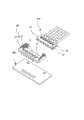
图2是图1的分解结构示意图; Fig. 2 is a schematic diagram of an exploded structure of Fig. 1;
图3是图2中各个组件的分解图; Fig. 3 is an exploded view of each component in Fig. 2;
图4是本实用新型之实施例中板端连接器的立体结构示意图; Fig. 4 is a schematic diagram of the three-dimensional structure of the board end connector in the embodiment of the present invention;
图5是本实用新型之实施例的截面示意图; Fig. 5 is a schematic cross-sectional view of an embodiment of the utility model;
图6是本实用新型之实施例中连接有导线的线端端子的放大示意图; Fig. 6 is an enlarged schematic view of a wire end terminal connected with a wire in an embodiment of the present invention;
图7是图6之线端端子夹紧板端端子的状态示意图; Fig. 7 is a schematic diagram of the state of clamping the board end terminal by the wire end terminal in Fig. 6;
图8是本实用新型之实施例中线端本体的立体结构示意图。 Fig. 8 is a three-dimensional structural schematic diagram of the wire end body in the embodiment of the present invention.
附图标识说明: Explanation of the accompanying drawings:
100、板端连接器 100. Board end connector
10、板端本体 11、底板
10.
111、板端端子槽 12、左侧板
111.
13、右侧板 14、前侧板
13.
141、卡槽 15、插接槽
141.
16、嵌合凹槽 161、凹部
16.
17、限位槽 18、第一扣合凸块
17. Limiting
20、板端端子 21、接触部
20.
22、固持部 23、焊接部
22. Holding
30、金属叉片 31、嵌合部
30.
311、凸块 32、夹紧勾部
311.
322、第二扣合凸块 33、焊脚部 322. The second fastening bump 33. Welding leg
200、线端连接器 200, line end connector
40、线端本体 41、线端端子槽
40.
42、扣孔 43、第一扣合凹槽
42.
431、导引斜面 44、第二扣合凹槽
431. Guide
45、前端面 46、侧面 45. Front face 46. Side
50、线端端子 51、连接部
50.
52、固持部 521、底板 52. Holding part 521. Bottom plate
522侧板 523、卡块 522 side plate 523, block
53、夹紧部 531、夹口
53. Clamping
532、夹紧片 60、导线
532. Clamping
300、PCB板 70、插孔。
300.
具体实施方式 Detailed ways
请参照图1至图3所示,其显示出了本实用新型之较佳实施例的具体结构,该电连接器组件包括有板端连接器100和线端连接器200,该板端连接器100固定在PCB板300上,该线端连接器200插拔于板端连接器100中,以实现电信号的接通传输。
Please refer to Fig. 1 to Fig. 3, which shows the specific structure of a preferred embodiment of the present invention, the electrical connector assembly includes a
其中,如图3所示,该板端连接器100包括有板端本体10、嵌装在板端本体10上的数个板端端子20及金属叉片30。该板端本体10是绝缘材料制成,该板端端子20和金属叉片30是导体材料制成。
Wherein, as shown in FIG. 3 , the
所述板端本体10包括一贴合在PCB板300上的底板11以及自底板11的三个周沿向上延伸形成左侧板12、右侧板13、前侧板14,该左侧板12、右侧板13、前侧板14及前述底板11围合形成有一大约呈长方形的插接槽15,该插接槽15为向上开口结构,其大小与前述线端连接器200相适配,以使线端连接器200可以自上而下插装在该插接槽15中。
The
该底板11的前端开设有数个板端端子槽111,各板端端子槽111与底板11的底面相通,每个板端端子槽111对应安装一个板端端子20,并且该板端端子槽111还向上延伸贯穿到前侧板14的顶面,在前侧板14上形成卡槽141,使板端端子槽111形成F字形状。该左侧板12和右侧板13为彼此对称结构,左侧板12和右侧板13上均设有L字结构的嵌合凹槽16,该嵌合凹槽16与插接槽15的内壁面之间的塑胶下凹形成有凹部161,该凹部161配合嵌合凹槽16用于安装前述金属叉片30。
The front end of the
如图4所示,该插接槽15的前端的前侧板14内壁面两侧凹设有限位槽17,该限位槽17自前侧板14的内壁面一直延伸贯穿到底板11的背面。并且,该前侧板14与左侧板12接合位置的顶沿、以及前侧板14与右侧板13接合位置的顶沿一体向外延伸出有第一扣合凸块18,该第一扣合凸块18位于限位槽17的上方。
As shown in FIG. 4 , both sides of the inner wall of the
结合图3和图4所示,所述金属叉片30有两个,该两金属叉片30彼此左右对称,两金属叉片30均包括一体成型的嵌合部31、夹紧勾部32和焊脚部33,该嵌合部31和焊脚部33插入到前述板端本体10的嵌合凹槽16中,该夹紧勾部32挂于凹部161中并夹紧凹部161的两侧壁。本实施例中,该嵌合部31呈薄片状,嵌合部31的底端一体延伸有数个凸块311,用于咬紧在嵌合凹槽16的底面,该夹紧勾部32是自嵌合部31的顶沿反向折弯延伸形成,该嵌合部31的尾端折弯后向下延伸形成前述焊脚部33,该焊脚部33穿过嵌合凹槽16,通过高温锡膏固定到PCB板300预设的插孔70中。除此之外,该夹紧勾部32设有一露出在插接槽15中的第二扣合凸块322,用于抵紧在线端连接器200的两侧。
As shown in FIG. 3 and FIG. 4, there are two
如图3所示,所述数个板端端子20整齐地安装在各自对应的板端端子槽111中。各板端端子20大致呈平板状的F字结构,具体而言,该板端端子20包括一体成型的接触部21、固持部22和焊接部23。组装时,该F字形装的板端端子20对应安装到前述F字形的板端端子槽111中,使接触部21露出板端端子槽111外、伸出在插接槽15中,该固持部22嵌入到前侧板14的卡槽141中,焊接部23伸出到前侧板14的外侧面,通过高温锡膏固定到PCB板300上。
As shown in FIG. 3 , the plurality of
承上,如图2和图3所示,所述线端连接器200包括线端本体40、插装在该线端本体40中的数个线端端子50和连接在该数个线端端子50上的数条导线60。其中,该线端本体40是由塑胶材料制成,该线端端子50是用导电性能良好的金属材料制成。
2 and 3, the wire-
具体而言,如图6和图7所示,该线端端子50与平板状的板端端子20连接。各线端端子50包括依次连接的连接部51、固持部52和夹紧部53,该连接部51用于与导线60连接,该夹紧部53用于夹紧板端端子20(见图7)。本实施例中,该固持部52的截面呈U字形结构,其包括底板521和自底板521两侧向上延伸出两侧板522,该底板521的外侧凸设有卡块523(见图3)。该夹紧部53包括自两侧板522的前端面45一体向前延伸向内折弯形成两夹紧片532,该两夹紧片532之间形成用于夹住板端端子20的夹口531,且该夹紧片532的头端向外翻折边以引导板端端子20。
Specifically, as shown in FIGS. 6 and 7 , the
如图8所示,所述线端本体40呈一长方体状,线端本体40上设有数个线端端子槽41,各线端端子槽41自线端本体40的后端面一直延伸贯穿至前端面45,如图3所示,针对前述线端端子50上所设的卡块523,于该线端本体40之顶面设有连通到线端端子槽41中的扣孔42,各线端端子50从线端本体40的后方插入到对应的线端端子槽41中,卡块523对应卡紧在扣孔42中(见图2)。当该线端连接器200插接到板端连接器100中时,板端连接器100上的板端端子20插入到线端端子槽41的前端,与线端端子50抵接。
As shown in FIG. 8 , the
承上,该线端本体40之前端面45两侧设有第一扣合凹槽43,该第一扣合凹槽43内具有一自前方向后上方倾斜的导引斜面431,使第一扣合凹槽与第一扣合凸块的配合更为贴合、紧密,且限位槽17上方的第一扣合凸块18挡在导引斜面431上(见图5)。针对前述板端连接器100两侧金属叉片30上的第二扣合凸块322,该线端连接器200之线端本体40两侧面46设有第二扣合凹槽44,当线端连接器200滑入到插接槽15中与板端连接器100连接时,该第二扣合凸块322扣合在第二扣合凹槽44中。
On the other hand, the two sides of the
本实用新型的组装的使用可以按以下方式进行: The use of assembling of the present utility model can be carried out in the following manner:
步骤一,将各板端端子20从底部向上整齐地压装到板端本体10所设的板端端子槽111中。
Step 1: press-fit each
步骤二,将两金属叉片30对应按压进左侧板12和右侧板13的嵌合凹槽16中,使第二扣合凸块322露出在插接槽15中。
Step 2, press the two
步骤三,通过高温锡膏将板端端子20的焊接部23以及金属叉片30的焊脚部33固定到PCB板300预设的插孔70中。
Step 3: Fix the
步骤四、将各导线60对应固定在线端端子50的连接部51。
Step 4: Fix each
步骤五、将连接有导线60的线端端子50插入到线端本体40的线端端子槽41中,使线端端子50之连接部51上的卡块523扣于线端本体40的扣孔42中。
Step 5: Insert the
步骤六、使组装好的线端连接器200插入到板端连接器100的插接槽15中,该线端连接器200之线端本体40前端两侧的第一扣合凹槽43在导引斜面431的作用下对应滑入板端连接器100之板端本体10的限位槽17中,该限位槽17上方的第一扣合凸块18挡在第一扣合凹槽43的导引斜面431上;同时板端连接器100之金属叉片30上的第法国二扣合凸块322扣合在线端连接器200之线端本体40两侧的第二扣合凹槽44中;此时,板端端子20的接触部21嵌入到线端连接器200之线端本体40的线端端子槽41前端,被咬紧在线端端子50头部两夹紧片532之间的夹口531中,籍此,实现板端连接器100与线端连接器200的电性连接。
Step 6: Insert the assembled
本实用新型的设计重点在于: The design focus of the present utility model is:
一、通过在板端连接器之板端本体上取消了插接槽两侧设置的第二扣合凸块,取而代之将其设置在金属叉片上,金属叉片冲压成型后再组装到板端本体两侧,降低整体零部件的复杂性,使单个部件结构变得更简单,有利于降低产品的加工难度,提高注塑成型出的成品优良率,并且使产品整体感觉平整、形状规则,确保产品的美观性。 1. By canceling the second buckle protrusions on both sides of the insertion groove on the board body of the board connector, they are replaced by setting them on the metal fork, and the metal fork is stamped and then assembled to the board body On both sides, reduce the complexity of the overall parts, make the structure of a single part simpler, help reduce the processing difficulty of the product, improve the excellent rate of finished products produced by injection molding, and make the overall feeling of the product smooth and regular in shape, ensuring the product's aesthetics.
二、通过在第一扣合凹槽中设置导引斜面,使第一扣合凹槽与第一扣合凸块的配合更为贴合、紧密。 2. By providing a guide inclined surface in the first fastening groove, the first fastening groove and the first fastening protrusion can be matched more tightly.
三、将线端端子之夹口两边夹紧片设置成向外翻折边结构,由于夹口原本就很小,通过向外翻折弯以引导板端端子插入到该夹口中,使板端端子与线端端子的连接更为容易。 3. Set the clamping pieces on both sides of the clamp of the wire end terminal to an outwardly folded edge structure. Since the clamp is originally small, the board terminal is inserted into the clamp by bending outward to guide the board end. It is easier to connect the terminal to the wire end terminal.
四、通过在线端端子上设置卡块,该卡块卡紧在线端本体中,使线端端子与线端本体的连接更为牢靠。 4. By arranging a clamping block on the wire end terminal, the clamping block is fastened in the wire end body, so that the connection between the wire end terminal and the wire end body is more reliable.
以上所述,仅是本实用新型的较佳实施例而已,并非对本实用新型的技术范围作任何限制,故凡是依据本实用新型的技术实质对以上实施例所作的任何细微修改、等同变化与修饰,均仍属于本实用新型技术方案的范围内。 The above are only preferred embodiments of the present utility model, and do not limit the technical scope of the present utility model, so any minor modifications, equivalent changes and modifications made to the above embodiments according to the technical essence of the present utility model , all still belong to the scope of the technical solution of the utility model.
Claims (10)
Priority Applications (1)
| Application Number | Priority Date | Filing Date | Title |
|---|---|---|---|
| CN 201120559056 CN202474337U (en) | 2011-12-29 | 2011-12-29 | Electrical connector assembly |
Applications Claiming Priority (1)
| Application Number | Priority Date | Filing Date | Title |
|---|---|---|---|
| CN 201120559056 CN202474337U (en) | 2011-12-29 | 2011-12-29 | Electrical connector assembly |
Publications (1)
| Publication Number | Publication Date |
|---|---|
| CN202474337U true CN202474337U (en) | 2012-10-03 |
Family
ID=46922468
Family Applications (1)
| Application Number | Title | Priority Date | Filing Date |
|---|---|---|---|
| CN 201120559056 Expired - Fee Related CN202474337U (en) | 2011-12-29 | 2011-12-29 | Electrical connector assembly |
Country Status (1)
| Country | Link |
|---|---|
| CN (1) | CN202474337U (en) |
Cited By (5)
| Publication number | Priority date | Publication date | Assignee | Title |
|---|---|---|---|---|
| CN103811910A (en) * | 2014-02-07 | 2014-05-21 | 连展科技电子(昆山)有限公司 | Electric connector |
| CN103855535A (en) * | 2012-12-07 | 2014-06-11 | 贝尔威勒电子股份有限公司 | Wire-to-Board Connector Assemblies with Pull Mechanism |
| CN104617424A (en) * | 2013-11-05 | 2015-05-13 | 宇宙电子株式会社 | Connector for Flat Cable |
| CN110324522A (en) * | 2019-07-05 | 2019-10-11 | 宁波为森智能传感技术有限公司 | Vehicle-mounted module group assembling technique |
| WO2024124433A1 (en) * | 2022-12-14 | 2024-06-20 | Amphenol Commercial Products (Chengdu) Co., Ltd. | Connector interface for engagement with plate |
-
2011
- 2011-12-29 CN CN 201120559056 patent/CN202474337U/en not_active Expired - Fee Related
Cited By (7)
| Publication number | Priority date | Publication date | Assignee | Title |
|---|---|---|---|---|
| CN103855535A (en) * | 2012-12-07 | 2014-06-11 | 贝尔威勒电子股份有限公司 | Wire-to-Board Connector Assemblies with Pull Mechanism |
| CN104617424A (en) * | 2013-11-05 | 2015-05-13 | 宇宙电子株式会社 | Connector for Flat Cable |
| CN104617424B (en) * | 2013-11-05 | 2017-04-12 | 宇宙电子株式会社 | Connector for Flat Cable |
| CN103811910A (en) * | 2014-02-07 | 2014-05-21 | 连展科技电子(昆山)有限公司 | Electric connector |
| CN103811910B (en) * | 2014-02-07 | 2018-03-09 | 连展科技电子(昆山)有限公司 | Electric connector |
| CN110324522A (en) * | 2019-07-05 | 2019-10-11 | 宁波为森智能传感技术有限公司 | Vehicle-mounted module group assembling technique |
| WO2024124433A1 (en) * | 2022-12-14 | 2024-06-20 | Amphenol Commercial Products (Chengdu) Co., Ltd. | Connector interface for engagement with plate |
Similar Documents
| Publication | Publication Date | Title |
|---|---|---|
| CN204333399U (en) | Reversible power plug connector | |
| US9960514B1 (en) | Double-sided pluggable power plug, power socket and combination structure thereof | |
| CN204834939U (en) | USB Type-C solderless connection structure | |
| CN223427797U (en) | Sinking plate type connector | |
| TWM431462U (en) | Electrical connector assembly | |
| CN203911045U (en) | Battery connector terminal, battery connector and mobile phone | |
| CN202454775U (en) | Micro USB 3.0 Dual Row Receptacle Connector | |
| CN202205949U (en) | electrical connector | |
| CN104538773B (en) | Reversible power plug connector | |
| CN204030062U (en) | a cable connector | |
| CN203326277U (en) | Easy-swap strip connectors | |
| CN204464549U (en) | The structure-improved of binding post | |
| CN204156225U (en) | Connectors with an integrated structure of shielding sheet and snap spring arm | |
| CN203326192U (en) | Fpc connector | |
| TW200908465A (en) | Adsorption cover for connector | |
| TWM335819U (en) | Memory card connector | |
| CN201307595Y (en) | A solar battery panel connecting box | |
| TW200929740A (en) | Connector and connecting structure of circuits | |
| TWI331827B (en) | Electrical connector and method of manufacturing the same | |
| CN201303075Y (en) | Card connector | |
| CN206076579U (en) | Ultra-thin Audio Video Connector | |
| CN200979912Y (en) | A piercing electrical connector | |
| CN202172155U (en) | Multi-interface combined electrical connector | |
| CN202142745U (en) | electronic card connector | |
| CN201146284Y (en) | Board-to-Board Connector |
Legal Events
| Date | Code | Title | Description |
|---|---|---|---|
| C14 | Grant of patent or utility model | ||
| GR01 | Patent grant | ||
| CF01 | Termination of patent right due to non-payment of annual fee | ||
| CF01 | Termination of patent right due to non-payment of annual fee |
Granted publication date: 20121003 Termination date: 20171229 |