CN202473555U - Main-auxiliary sheath high-frequency transformer - Google Patents
Main-auxiliary sheath high-frequency transformer Download PDFInfo
- Publication number
- CN202473555U CN202473555U CN2012201031605U CN201220103160U CN202473555U CN 202473555 U CN202473555 U CN 202473555U CN 2012201031605 U CN2012201031605 U CN 2012201031605U CN 201220103160 U CN201220103160 U CN 201220103160U CN 202473555 U CN202473555 U CN 202473555U
- Authority
- CN
- China
- Prior art keywords
- skeleton
- secondary winding
- primary
- frequency transformer
- winding skeleton
- Prior art date
- Legal status (The legal status is an assumption and is not a legal conclusion. Google has not performed a legal analysis and makes no representation as to the accuracy of the status listed.)
- Expired - Fee Related
Links
- 238000004804 winding Methods 0.000 claims abstract description 86
- 230000002349 favourable effect Effects 0.000 abstract 2
- 230000006978 adaptation Effects 0.000 description 1
- 230000000694 effects Effects 0.000 description 1
- 238000005516 engineering process Methods 0.000 description 1
- 238000009413 insulation Methods 0.000 description 1
- 238000012986 modification Methods 0.000 description 1
- 230000004048 modification Effects 0.000 description 1
Images



Landscapes
- Insulating Of Coils (AREA)
Abstract
The utility model discloses a main-auxiliary sheath high-frequency transformer which comprises a frame, a magnetic core and a pin end, wherein the pin end is connected with the frame; the frame is composed of a primary winding frame and a secondary winding frame; the pin end comprises a primary winding pin end and a secondary winding pin end; the primary winding pin end is connected with one end of the primary winding frame; the secondary winding pin end is connected with one end of the secondary winding frame; the primary winding frame is sheathed in the cavity of the secondary winding frame; both ends of the primary winding frame are provided with convex edges; the convex edges contact the inner wall of the cavity of the secondary winding frame; the convex edges on the two sides form a mounting space of the primary winding; both ends of the secondary winding frame are respectively provided with a magnetic core mounting rack; and a secondary winding mounting space is formed between the mounting racks on the two ends. The main-auxiliary sheath high-frequency transformer disclosed by the utility model has the advantages of automatic wire winding, favorable voltage endurance and favorable insulativity, and is convenient for assembly.
Description
Technical field
The utility model relates to transformer, specifically is meant a kind of primary and secondary cover high frequency transformer.
Background technology
The skeleton of existing primary and secondary cover high frequency transformer has only one, and elementary winding and secondary winding are separately positioned on the skeleton, and in order to satisfy the requirement of safety, needing increases margin tape or three layer insulation wire, and its coiling needs manual operation, withstand voltage poor effect.
The utility model content
The purpose of the utility model provides a kind of automation that winds the line, withstand voltage insulating properties primary and secondary cover high frequency transformer good, easy to assembly.
To achieve these goals; The utility model is designed a kind of primary and secondary cover high frequency transformer, and it comprises skeleton, magnetic core and stitch end, and the stitch end is connected with skeleton; Described skeleton is made up of elementary winding skeleton and secondary winding skeleton; The stitch end includes elementary winding stitch end and secondary winding stitch end, and elementary winding stitch end is connected with the lower end of elementary winding skeleton, and secondary winding stitch end is connected with the lower end of secondary winding skeleton; Described elementary winding skeleton is sleeved in the cavity of secondary winding skeleton, and the two ends of elementary winding skeleton are provided with the convex edge, and the convex edge of upper end contacts with the cavity inner wall of secondary winding skeleton, and the convex edge, both sides forms elementary winding installing space; The two ends of secondary winding skeleton are provided with the magnetic core installing rack, between the installing rack at two ends, form the secondary winding installing space.
It is protruding that the outside of the convex edge of described elementary winding skeleton upper end is provided with a circle, forms groove between the protruding and elementary winding skeleton.
Described elementary winding skeleton upper end also is provided with a circle boss.
The upper end inner chamber of described secondary winding skeleton forms and the corresponding projection of groove.
The upper end inner chamber of described secondary winding skeleton forms and the corresponding step of boss.
Respectively on different skeletons, two skeletons adopt the mode of primary and secondary suit to the utility model primary and secondary cover high frequency transformer, can improve withstand voltage insulating properties, can make elementary winding and secondary winding enforcement automated job simultaneously with elementary winding and secondary winding.On elementary winding skeleton and secondary winding skeleton, increase groove and projection prolongation creepage distance.
Description of drawings:
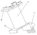
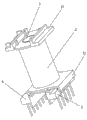
Fig. 1 is the elementary winding skeleton structure sketch map of the utility model primary and secondary cover high frequency transformer;
Fig. 2 is the secondary winding skeleton structure sketch map of the utility model primary and secondary cover high frequency transformer;
Fig. 3 is the perspective view after the skeleton of the utility model primary and secondary cover high frequency transformer is assembled;
Fig. 4 is another angle perspective view after the skeleton of the utility model primary and secondary cover high frequency transformer is assembled;
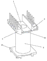
Fig. 5 is the perspective view of the utility model primary and secondary cover high frequency transformer;
Fig. 6 is the internal view of the utility model primary and secondary cover high frequency transformer.
Embodiment
For the ease of those skilled in the art's understanding, will combine specific embodiment and accompanying drawing that the structural principle of the utility model is done further to describe in detail below.
Like Fig. 1-shown in Figure 6; A kind of primary and secondary cover high frequency transformer, it comprises skeleton, magnetic core 10 and stitch end, the stitch end is connected with skeleton; Described skeleton is made up of with secondary winding skeleton 2 elementary winding skeleton 1; The stitch end includes elementary winding stitch end 3 and secondary winding stitch end 4, and elementary winding stitch end 3 is connected with the lower end of elementary winding skeleton 1, and secondary winding stitch end 4 is connected with the lower end of secondary winding skeleton 2; Described elementary winding skeleton 1 is sleeved in the cavity of secondary winding skeleton 2, and the two ends of elementary winding skeleton 1 are provided with convex edge 11, and the convex edge 11 of upper end contacts with the cavity inner wall of secondary winding skeleton 2, and convex edge, both sides 11 forms elementary winding installing space 12; The two ends of secondary winding skeleton 2 are provided with magnetic core 10 installing racks 21, between the installing rack 21 at two ends, form secondary winding installing space 18.
As shown in Figure 1, the outside of the convex edge 11 of described elementary winding skeleton 1 upper end is provided with between a circle protruding 13, protruding 13 and the elementary winding skeleton 1 and forms groove 14.
As shown in Figure 1, described elementary winding skeleton 1 upper end also is provided with a circle boss 16.
As shown in Figure 6, the upper end inner chamber of described secondary winding skeleton 2 forms and groove 14 corresponding projections 23.
As shown in Figure 6, the upper end inner chamber of described secondary winding skeleton 2 forms and boss 16 corresponding steps 17.
The utility model increases creepage distance through groove 14, boss 16 and projection 23, step 17, satisfies the requirement of safety, further improves withstand voltage performance.
Foregoing is merely the preferred embodiment of the utility model, is not the embodiment that is used to limit the utility model, and those skilled in the art are according to the design of the utility model, and appropriate adaptation of having done or modification all should be within the protection ranges of the utility model.
Claims (5)
1. a primary and secondary overlaps high frequency transformer; Comprise skeleton, magnetic core (10) and stitch end; The stitch end is connected with skeleton, it is characterized in that: described skeleton is made up of elementary winding skeleton (1) and secondary winding skeleton (2), and the stitch end includes elementary winding stitch end (3) and secondary winding stitch end (4); Elementary winding stitch end (3) is connected with the lower end of elementary winding skeleton (1), and secondary winding stitch end (4) is connected with the lower end of secondary winding skeleton (2); Described elementary winding skeleton (1) is sleeved in the cavity of secondary winding skeleton (2); The two ends of elementary winding skeleton (1) are provided with convex edge (11); The convex edge (11) of upper end contacts with the cavity inner wall of secondary winding skeleton (2), and convex edge, both sides (11) form elementary winding installing space (12); The two ends of secondary winding skeleton (2) are provided with magnetic core (10) installing rack (21), between the installing rack (21) at two ends, form secondary winding installing space (18).
2. primary and secondary cover high frequency transformer according to claim 1; It is characterized in that: the outside of the convex edge (11) of described elementary winding skeleton (1) upper end is provided with a circle protruding (13), forms groove (14) between protruding (13) and the elementary winding skeleton (1).
3. primary and secondary cover high frequency transformer according to claim 2 is characterized in that: described elementary winding skeleton (1) upper end also is provided with a circle boss (16).
4. according to claim 2 or 3 described primary and secondary cover high frequency transformers, it is characterized in that: the upper end inner chamber of described secondary winding skeleton (2) forms and the corresponding projection of groove (14) (23).
5. primary and secondary cover high frequency transformer according to claim 4, it is characterized in that: the upper end inner chamber of described secondary winding skeleton (2) forms and the corresponding step of boss (16) (17).
Priority Applications (1)
| Application Number | Priority Date | Filing Date | Title |
|---|---|---|---|
| CN2012201031605U CN202473555U (en) | 2012-03-19 | 2012-03-19 | Main-auxiliary sheath high-frequency transformer |
Applications Claiming Priority (1)
| Application Number | Priority Date | Filing Date | Title |
|---|---|---|---|
| CN2012201031605U CN202473555U (en) | 2012-03-19 | 2012-03-19 | Main-auxiliary sheath high-frequency transformer |
Publications (1)
| Publication Number | Publication Date |
|---|---|
| CN202473555U true CN202473555U (en) | 2012-10-03 |
Family
ID=46921699
Family Applications (1)
| Application Number | Title | Priority Date | Filing Date |
|---|---|---|---|
| CN2012201031605U Expired - Fee Related CN202473555U (en) | 2012-03-19 | 2012-03-19 | Main-auxiliary sheath high-frequency transformer |
Country Status (1)
| Country | Link |
|---|---|
| CN (1) | CN202473555U (en) |
Cited By (2)
| Publication number | Priority date | Publication date | Assignee | Title |
|---|---|---|---|---|
| CN109285661A (en) * | 2017-07-21 | 2019-01-29 | Tdk株式会社 | Coil device |
| CN115621016A (en) * | 2022-10-10 | 2023-01-17 | 中山市迪卡森电子有限公司 | A high voltage transformer |
-
2012
- 2012-03-19 CN CN2012201031605U patent/CN202473555U/en not_active Expired - Fee Related
Cited By (3)
| Publication number | Priority date | Publication date | Assignee | Title |
|---|---|---|---|---|
| CN109285661A (en) * | 2017-07-21 | 2019-01-29 | Tdk株式会社 | Coil device |
| CN109285661B (en) * | 2017-07-21 | 2020-07-28 | Tdk株式会社 | Coil device |
| CN115621016A (en) * | 2022-10-10 | 2023-01-17 | 中山市迪卡森电子有限公司 | A high voltage transformer |
Similar Documents
| Publication | Publication Date | Title |
|---|---|---|
| CN204215881U (en) | A kind of variable inductor | |
| CN204315356U (en) | Inductor | |
| CN201698882U (en) | Epoxide resin type ignition coil | |
| CN205959731U (en) | High power inductors of modularized design | |
| CN209912700U (en) | Low leakage inductance noise reduction type transformer | |
| CN204068658U (en) | Integrated structure of transformer and inductor | |
| CN202523528U (en) | Transformer for charger power | |
| CN203338918U (en) | Light thin transformer | |
| CN204102695U (en) | Current transformer | |
| CN204088025U (en) | Data center's k-factor transformer | |
| CN203338939U (en) | Widened framework used for transformer | |
| CN207474253U (en) | A kind of multi-layer FPC loop construction for wireless charging | |
| CN203812700U (en) | Safety LED convertor | |
| CN104217846A (en) | Inductor | |
| CN202905445U (en) | Built-in type voltage transformer | |
| CN204668076U (en) | Common-mode inductor | |
| CN202513016U (en) | High-power panel transformer | |
| CN204303517U (en) | Dry type many pulse waves output transformer | |
| CN205039061U (en) | High -frequency switching mode power supply transformer | |
| CN202736663U (en) | Dry type transformer coil structure | |
| CN204102683U (en) | A kind of increase safe distance transformer framework combination | |
| CN202422941U (en) | Ferrite core | |
| CN102709029A (en) | Ferrite magnetic core | |
| CN202512988U (en) | Large-current panel inductor | |
| CN207818338U (en) | A Planar High Frequency Transformer |
Legal Events
| Date | Code | Title | Description |
|---|---|---|---|
| C14 | Grant of patent or utility model | ||
| GR01 | Patent grant | ||
| CF01 | Termination of patent right due to non-payment of annual fee | ||
| CF01 | Termination of patent right due to non-payment of annual fee |
Granted publication date: 20121003 Termination date: 20160319 |