CN202468713U - Easy-lubricating isolating block for bearing - Google Patents
Easy-lubricating isolating block for bearing Download PDFInfo
- Publication number
- CN202468713U CN202468713U CN2011205531704U CN201120553170U CN202468713U CN 202468713 U CN202468713 U CN 202468713U CN 2011205531704 U CN2011205531704 U CN 2011205531704U CN 201120553170 U CN201120553170 U CN 201120553170U CN 202468713 U CN202468713 U CN 202468713U
- Authority
- CN
- China
- Prior art keywords
- spacing block
- bearing
- concave arc
- groove
- arc surface
- Prior art date
- Legal status (The legal status is an assumption and is not a legal conclusion. Google has not performed a legal analysis and makes no representation as to the accuracy of the status listed.)
- Expired - Fee Related
Links
- 238000005096 rolling process Methods 0.000 abstract description 5
- 230000002093 peripheral effect Effects 0.000 abstract 1
- 239000004519 grease Substances 0.000 description 7
- 239000000314 lubricant Substances 0.000 description 5
- 230000001050 lubricating effect Effects 0.000 description 4
- 238000000034 method Methods 0.000 description 4
- 238000005461 lubrication Methods 0.000 description 2
- 239000002994 raw material Substances 0.000 description 2
- 230000009286 beneficial effect Effects 0.000 description 1
- 230000007812 deficiency Effects 0.000 description 1
- 230000002950 deficient Effects 0.000 description 1
- 238000004519 manufacturing process Methods 0.000 description 1
- 239000007787 solid Substances 0.000 description 1
Images

Landscapes
- Rolling Contact Bearings (AREA)
Abstract
The utility model belongs to the field of bearings, and particularly discloses an easy-lubricating isolating block for a bearing, which includes an isolating block with the two ends provided with concave arc surfaces, wherein a concave groove is arranged at the center of the bottom part of the concave arc surface, and an annular groove concentric with the concave groove is arranged at the middle part of the concave arc surface; a plurality of oil grooves are symmetrically extended from the concave groove to the edges of the concave arc surface and crossed and communicated with the annular groove; and a plurality of sunken parts are uniformly distributed at the middle part of the outer peripheral surface of the isolating block body, and the depth of the sunken part is smaller than the half of the radius of the isolating block body. The isolating block can effectively lubricate the surfaces of the balls contacted with the concave arc surfaces of the isolating block during the operation of the bearing, so as to prevent the reduction of the service life of the bearing due to the over-dry rolling of the balls of the bearing.
Description
[technical field]
The utility model relates to field of bearings, especially relates to a kind of easy lubricated spacing block of bearing usefulness that can carry out effectively lubricating to the ball in the bearing.
[background technique]
Known, common retainer has two kinds in bearing, and a kind of is the arc retainer, the spacing block retainer that another kind is made up of a plurality of spacing blocks; In conjunction with accompanying drawing 1; What select for use basically in the spacing block retainer at present is the spacing block of solid cylinder body structure; The concave arc surface that its two ends are equipped with corresponding ball surface advances so that make ball in rolling process, promote spacing block, i.e. spacing block and ball same moved further on raceway; Because bearing is in operation process; Its switching-over and impulsive load fray for fear of ball to producing bigger influence the working life of ball, guarantee the starting torque and the running accuracy of bearing; Improve the whole service life of bearing; Sufficient lubricating just must be arranged between spacing block and the ball, but because the reasons in structure of existing spacing block, the lubricant grease on ball surface is prone to scraped stripping by the concave arc surface edge of spacing block in the rolling process of ball; Thereby it is lubricated fully to make the ball surface that contacts with the spacing block concave arc surface be difficult to obtain; Therefore very easily cause bearing under the state of lack of lubrication, to run up, make the surface of ball produce rigid friction, thereby make spacing block make its concave arc surface that the damage phenomenon takes place because of frictional force is excessive at the long-time concave arc surface that rolls back and spacing block; And then cause bearing effectively to turn round, promptly reduced the running life of bearing.
[summary of the invention]
In order to overcome the deficiency in the background technique; The utility model discloses a kind of bearing with being prone to lubricated spacing block; Described spacing block can make the ball surface that contacts with the spacing block concave arc surface obtain effective lubricating in the bearing working process, thereby has avoided bearing to cross the phenomenon generation that the drought rolling influences the reduction of bearing operation life-span because of ball.
To achieve these goals, the utility model adopts following technological scheme:
A kind of bearing is with being prone to lubricated spacing block, and described spacing block comprises the spacing block body that two ends are equipped with concave arc surface; The bottom centre of said concave arc surface is provided with groove, and is provided with an annular groove concentric with groove at the medium position of concave arc surface; Described groove extends many oil grooves to concave arc surface edge symmetry, and oil groove intersects perforation with annular groove respectively; Described spacing block body outer circumferential face middle part is provided with a plurality of depressions uniformly, and the depth dimensions of depression half the less than spacing block body radius size.
Described bearing is with being prone to lubricated spacing block, and the said oil groove correspondence that is positioned at spacing block body two ends is staggered.
Described bearing is with being prone to lubricated spacing block, and described oil groove is made as 4~8, and depression is made as 4~8.
Described bearing is with being prone to lubricated spacing block, and described oil groove is made as 4, and depression is made as 4.
Described bearing is with being prone to lubricated spacing block, and described depression is located on the corresponding spacing block body outer circumferential face in interval between per two oil grooves of same end face.
Owing to adopt aforesaid technological scheme, the utlity model has following beneficial effect:
Described bearing is with being prone to lubricated spacing block; Through effectively having reduced the area of contact between ball and the spacing block at the groove that is provided with on the concave arc surface of spacing block body, annular groove and oil groove; The corresponding frictional force that has reduced between ball and the spacing block body; And can't store the defective of grease through the concave arc surface that the groove hole that is positioned at each groove on the concave arc surface has remedied spacing block; Thereby be able to utilize the lubricant grease in these grooves fully effectively the ball surface that contacts with the spacing block concave arc surface to be lubricated, avoided spending the running life that the drought rolling reduces bearing because of ball; In addition, reduce the used raw-material use amount of making spacing block, the corresponding effective cost of production of having practiced thrift through the depression that on the outer circumferential face of said spacing block, is provided with.
[description of drawings]
Fig. 1 is the side cut-away view of existing spacing block;
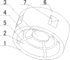
Fig. 2 is the schematic representation of the utility model.
Among the figure: 1, spacing block body; 2, concave arc surface; 3, groove; 4, annular groove; 5, oil groove; 6, outer circumferential face; 7, depression.
[embodiment]
Can explain the utility model in more detail through following embodiment, the purpose of open the utility model is intended to protect all variations and the improvement in the utility model scope, and the utility model is not limited to following embodiment;
With being prone to lubricated spacing block, described spacing block comprises the spacing block body 1 that two ends are equipped with concave arc surface 2 in conjunction with accompanying drawing 2 described bearings; Concave arc surface 2 bottom centre of said spacing block body 1 each end are equipped with groove 3; And be equipped with an annular groove 4 concentric with groove 3 at the medium position of each end concave arc surface 2, promptly annular groove 4 is with groove 3 edges of end face and the medium position between concave arc surface 2 edges; Described groove 3 extends many oil grooves 5 to the concave arc surface 2 edge symmetries with end face; Described oil groove 5 is preferably 4~8; Further then be preferably 4 again; And oil groove 5 intersects perforation respectively with the annular groove of end face 4 is corresponding, effectively the ball surface that contacts with concave arc surface 2 is lubricated thereby be utilized in the lubricant grease that stockpiles in groove 3, annular groove 4 and the oil groove 5, promptly when bearing operation; The lubricant grease on ball surface can flow into through the oil groove 5 outer end notches that are located at concave arc surface 2 edges in corresponding oil groove 5, annular groove 4 and the groove 3; And corresponding ball surface is lubricated, thereby the edge that has effectively reduced spacing block body 1 concave arc surface 2 scrape the phenomenon of stripping ball surface lubrication grease and take place, make the ball in the bearing have better lubricating condition; Described spacing block body 1 outer circumferential face 6 middle parts are provided with a plurality of depressions 7 uniformly; Described depression 7 is preferably 4~8; Further then be preferably 4 again; And 7 the depth dimensions of caving in half the less than spacing block body 1 radius size, thereby in the said spacing block intensity of unlikely influence, reduced the required raw-material use amount of making spacing block again;
In order to strengthen the effective intensity of said spacing block; Can the oil groove that be positioned at spacing block body 1 two ends 5 mutual correspondences be staggered; Perhaps, described depression 7 is located on the outer circumferential face 6 of the corresponding spacing block body 1 in interval between per two oil grooves 5 of same end face.
Implementing the described bearing of the utility model uses when being prone to lubricate spacing block; Only need described spacing block is assembled in the corresponding ball bearing; And make in described groove, annular groove and the oil groove and be filled with lubricant grease; Promptly can when this ball bearing running, carry out lubricated fully to the ball surface that contacts with spacing block body concave arc surface.
Carefully not stating in the above content is existing technology partly, does not state so run business into particular one.
Claims (5)
1. a bearing is with being prone to lubricated spacing block; Described spacing block comprises the spacing block body (1) that two ends are equipped with concave arc surface (2); It is characterized in that: the bottom centre of said concave arc surface (2) is provided with groove (3), and is provided with an annular groove (4) concentric with groove (3) at the medium position of concave arc surface (2); Described groove (3) extends many oil grooves (5) to concave arc surface (2) edge symmetry, and oil groove (5) intersects perforation with annular groove (4) respectively; Described spacing block body (1) outer circumferential face (6) middle part is provided with a plurality of depressions (7) uniformly, and the depth dimensions of depression (7) half the less than spacing block body (1) radius size.
2. bearing according to claim 1 is with being prone to lubricated spacing block, and it is characterized in that: said oil groove (5) correspondence that is positioned at spacing block body (1) two ends is staggered.
3. bearing according to claim 1 is with being prone to lubricated spacing block, and it is characterized in that: described oil groove (5) is made as 4~8, and described depression (7) is made as 4~8.
4. bearing according to claim 1 is with being prone to lubricated spacing block, and it is characterized in that: described oil groove (5) is made as 4, and described depression (7) is made as 4.
5. bearing according to claim 1 is characterized in that with being prone to lubricated spacing block: described depression (7) is located on corresponding spacing block body (1) outer circumferential face (6) in interval between per two oil grooves (5) of same end face.
Priority Applications (1)
| Application Number | Priority Date | Filing Date | Title |
|---|---|---|---|
| CN2011205531704U CN202468713U (en) | 2011-12-27 | 2011-12-27 | Easy-lubricating isolating block for bearing |
Applications Claiming Priority (1)
| Application Number | Priority Date | Filing Date | Title |
|---|---|---|---|
| CN2011205531704U CN202468713U (en) | 2011-12-27 | 2011-12-27 | Easy-lubricating isolating block for bearing |
Publications (1)
| Publication Number | Publication Date |
|---|---|
| CN202468713U true CN202468713U (en) | 2012-10-03 |
Family
ID=46916872
Family Applications (1)
| Application Number | Title | Priority Date | Filing Date |
|---|---|---|---|
| CN2011205531704U Expired - Fee Related CN202468713U (en) | 2011-12-27 | 2011-12-27 | Easy-lubricating isolating block for bearing |
Country Status (1)
| Country | Link |
|---|---|
| CN (1) | CN202468713U (en) |
Cited By (1)
| Publication number | Priority date | Publication date | Assignee | Title |
|---|---|---|---|---|
| CN116181804A (en) * | 2023-02-20 | 2023-05-30 | 瓦房店轴承集团国家轴承工程技术研究中心有限公司 | Bearing spacer |
-
2011
- 2011-12-27 CN CN2011205531704U patent/CN202468713U/en not_active Expired - Fee Related
Cited By (1)
| Publication number | Priority date | Publication date | Assignee | Title |
|---|---|---|---|---|
| CN116181804A (en) * | 2023-02-20 | 2023-05-30 | 瓦房店轴承集团国家轴承工程技术研究中心有限公司 | Bearing spacer |
Similar Documents
| Publication | Publication Date | Title |
|---|---|---|
| CN203214627U (en) | Centripetal bearing | |
| CN203670473U (en) | Cylindrical roller bearing | |
| CN102102710A (en) | Rolling bearing retainer with micro pits | |
| CN202867570U (en) | Inner Streamline structure sealing bearing of large-size ultralong rolling mill | |
| CN202746397U (en) | Spherical surface idler wheel type self-lubricating bearing | |
| CN201902452U (en) | Rolling bearing cage with dimples | |
| CN212155451U (en) | A high temperature resistant high speed deep groove ball bearing | |
| CN201982513U (en) | Easily-lubricated isolating block | |
| CN202073927U (en) | Bearing isolation block | |
| CN201982516U (en) | Roller bearing cage | |
| CN201802764U (en) | Conical roller bearing and retainer thereof | |
| CN202073926U (en) | Ball bearing isolation block | |
| CN201687859U (en) | Tapered roller bearing with spherical inner ring baffle edge face | |
| CN201599324U (en) | Isolation block for a turntable bearing | |
| CN206617432U (en) | A joint bearing structure | |
| CN204533196U (en) | A kind of novel bearing shell | |
| CN203441977U (en) | Novel ball bearing | |
| CN201763820U (en) | Bearing and retainer thereof | |
| CN201347981Y (en) | Double-row cylindrical roller bearing with oil holes | |
| CN202510554U (en) | Structurally improved bearing for agricultural machinery | |
| CN206290578U (en) | A kind of novel bearing | |
| CN101769320A (en) | Double-row tapered roller bearing provided with middle space rings and used for rolling mills | |
| CN203979172U (en) | Axle and needle bearing assembly structure and pad thereof | |
| CN202851619U (en) | Bent axle | |
| CN216279026U (en) | Tapered roller bearing |
Legal Events
| Date | Code | Title | Description |
|---|---|---|---|
| C14 | Grant of patent or utility model | ||
| GR01 | Patent grant | ||
| C17 | Cessation of patent right | ||
| CF01 | Termination of patent right due to non-payment of annual fee |
Granted publication date: 20121003 Termination date: 20121227 |