Four station valve body automatic processing machine tools
Technical field
The utility model relates to a kind of lathe, is specifically related to a kind of four station valve body automatic processing machine tools.
Background technology
Valve is the requisite easy consumption product of modern industry, agricultural, chemical industry and daily life, and its valve body mainly uses universal machine tools to process.Because the application of universal machine tools is wide, must process not smart, and product quality influenced by operator's human factor bigger, stability can not well be guaranteed.
In addition, a workpiece needs many lathes to accomplish jointly, adopts reaming lathe, tapper etc. respectively like needs.China's utility application 200910019846.9 discloses a kind of connector double-ended semiautomatic tapping machine, is used for the special purpose machine tool of machining screw exactly.The common method for processing of this many lathes needs a plurality of parts to have enough to meet the need, and causes production efficiency low.Along with the demand of market to the rotary body workpiece increases, the mode of production of obvious this poor efficiency has no longer adapted to the large-scale production of valve.
Summary of the invention
The utility model technical problem to be solved provides a kind of four station valve body automatic processing machine tools, and it can collect material loading, bore hole, tapping, discharging is one.
For solving the problems of the technologies described above, the technical solution of the utility model four station valve body automatic processing machine tools is:
Comprise rotary disk 13, rotary disk 13 is through clutch 44 connection gear 43; Under the effect of hydraulic cylinder, the tooth bar side-to-side movement drives gear 43 rotations that are engaged with, and gear 43 drives rotary disk 13 rotations through clutch 44, realizes the conversion of station; Be evenly equipped with four stations on the circumference of said rotary disk 13, first station be positioned at rotary disk 13 directly over, second station is positioned at the positive left of rotary disk 13, the 3rd station be positioned at rotary disk 13 under, the 4th station is positioned at the just right-hand of rotary disk 13; Workpiece to be processed is mounted the location on first station, on second station, carry out bore hole, on the 3rd station, carries out tapping, on the 4th station, takes off, and accomplishes material loading, bore hole, tapping, four operations of blanking.
Be respectively arranged with one group of lever clamping device on said each station, said lever clamping device comprises lever 30, and lever 30 is fixed on the cylindrical of rotary disk 13 through lever pole 29; The Partner of lever 30 connects release nut 11, discharges nut 11 and connects springs 33 through spring guide pillar 32; Spring 33 is fixedly set on the cylindrical of rotary disk 13; The drive end of lever 30 connects top board 16, and top board 16 connects lower platen 28 through guide rod 27; Lower platen 28 is fixedly set on the main bearing 12 of rotary disk 13.
The said lever clamping device that is in first station and the 4th station is respectively arranged with pneumatic pressing mechanism; Pneumatic pressing mechanism comprises and unloads carrier gas cylinder 8, unloads carrier gas cylinder 8 connects said lever clamping device through connecting rod 9 top board 16.
The said lever clamping device that is in second station and the 3rd station is respectively arranged with pneumatic load maintainer; Pneumatic load maintainer comprises and adds carrier gas cylinder 39, and the piston that adds carrier gas cylinder 39 connects load bars 36 through connecting rod 38, and load bar 36 connects the top board 16 of said lever clamping device; Drive connecting rod 38 through adding carrier gas cylinder 39, make 36 pairs of top board 16 application of forces of load bar, accomplish the loading in the process.
The both sides, front and back of said rotary disk 13 second stations are respectively arranged with a cover bore hole mechanism; Bore hole mechanism comprises bore hole main shaft 18, and bore hole main shaft 18 is provided with boring cutter 45; Bore hole main shaft 18 connects bore hole axis feeding driving mechanism and bore hole main axis rotation driving mechanism; Said bore hole axis feeding driving mechanism comprises feeding cylinder 20, and an end of said bore hole main shaft 18 connects the piston of feeding cylinder 20; Feeding cylinder 20 promotes boring cutter 45 and realizes the front and back feed motion; Said bore hole main axis rotation driving mechanism comprises rotary drive motor 2, and said bore hole main shaft 18 connects rotary drive motor 2 through belt wheel 19; Rotary drive motor 2 drives bore hole main shaft 18, realizes the rotation of boring cutter 45.
One end of said bore hole main shaft 18 connects double-direction thrust ball bearing 55, and double-direction thrust ball bearing 55 is arranged in the double-direction thrust ball bearing case 54, and double-direction thrust ball bearing case 54 connects the piston of feeding cylinder 20 through adapter sleeve capping 56.
Fixed cover is provided with axle sleeve 50 on the said bore hole main shaft 18, and axle sleeve 50 is connected with sleeve 48 through bearing 49; Boring cutter 45 is installed on the sleeve 48; One end of sleeve 48 connects axle head capping 51, and axle head capping 51 connects said bore hole main shaft 18.
The both sides, front and back of said rotary disk 13 the 3rd station are respectively arranged with a cover tapper mechanism; Tapper mechanism comprises tapping transmission case driving shaft 24, and tapping transmission case driving shaft 24 is provided with screw tap; One end of tapping transmission case driving shaft 24 connects screw tap advance and retreat control cylinder 23, and screw tap advance and retreat control cylinder 23 is used to control the front and back feed motion of tapping transmission case driving shaft 24, makes the screw tap contact on the tapping transmission case driving shaft 24 or leaves work piece; Be arranged with rotating control wheel 60 on the tapping transmission case driving shaft 24, rotating control wheel 60 connects the passive angular wheel 58,62 of forward and backward respectively through forward and reverse transmission cone friction drum 59,61; The passive angular wheel 58,62 of rotating is meshed with initiative taper generating gear 63, and initiative taper generating gear 63 connects belt wheel 65 through drive sprocket axle 64; Make drive sprocket axle 64 work through belt wheel 65 transmitting torques; Drive sprocket axle 64 drives 63 rotations of initiative taper generating gear; Initiative taper generating gear 63 and passive angular wheel 58,62 engagements of rotating; Drive passive angular wheel 58,62 rotations of rotating, the passive angular wheel 58,62 of rotating drives 60 rotations of rotating control wheel through forward and reverse transmission cone friction drum 59,61, thereby drives 24 rotatings of tapping transmission case driving shaft; Rotating control wheel 60 connects double-direction thrust ball bearing 79; Double-direction thrust ball bearing 79 is arranged in the double-direction thrust ball bearing casing 78; Double-direction thrust ball bearing casing 78 connects ball cup 67 through supporter 66; Be provided with bulb 68 in the ball cup 67, bulb 68 connects screw tap rotating control cylinder 22 through connector 70; Regulate double-direction thrust ball bearing 79 through screw tap rotating control cylinder 22; Rotating control wheel 60 is contacted with forward transmission cone friction drum 59 or reverse drive cone friction drum 61; Make tapping transmission case driving shaft 24 and just change passive angular wheel 58 or the passive angular wheel 62 that reverses is connected, to control the direction of rotation of tapping transmission case driving shaft 24.
One end of said tapping transmission case driving shaft 24 is connected with double-direction thrust ball bearing case 74 through connecting rod 75, is provided with double-direction thrust ball bearing 73 in the double-direction thrust ball bearing case 74; Double-direction thrust ball bearing case 74 connects the piston of screw tap advance and retreat control cylinder 23 through adapter sleeve cap seal 71.
The end face of said rotary disk 13 is provided with four station locating holes 34; One side of rotary disk 13 is provided with positioning cylinder 41; Aim at the station locating hole 34 that is in the below when positioning cylinder 41, can realize accurate location.
The technique effect that the utility model can reach is:
The utility model through rotary disk rotation and location so that accomplish material loading, bore hole, tapping, four operations of blanking; Can overcome the shortcoming that a workpiece need be processed on a plurality of lathes; Improve working (machining) efficiency greatly, save labor cost, and ensure product quality stability.
The slew gear of the utility model can be realized rotating and send part, only needs workpiece is positioned over anchor clamps, just can clamp automatically and deliver to processing stations, realizes automation processing.
The utility model can pick and place new work piece in bore hole, tapping, improve working (machining) efficiency greatly.
Description of drawings
Below in conjunction with the accompanying drawing and the specific embodiment the utility model is done further detailed explanation:
Fig. 1 is the structural representation of the utility model four station valve body automatic processing machine tools;
Fig. 2 is the vertical view of Fig. 1;
Fig. 3 is the structural representation of the slew gear of the utility model;
Fig. 4 is the A-A cutaway view among Fig. 3;
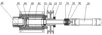
Fig. 5 is the structural representation of the bore hole mechanism of the utility model;
Fig. 6 is the partial schematic diagram of the tapper mechanism of the utility model;
Fig. 7 is another partial schematic diagram of the tapper mechanism of the utility model.
Description of reference numerals among the figure:
1 is frame, and 2 is rotary drive motor,
3 is support, 6 gripper shoes,
7 is main shaft,
8 for unloading carrier gas cylinder, and 9 is connecting rod,
11 for discharging nut, and 12 is rotary disk master bearing,
13 is rotary disk, and 16 is top board,
18 is the bore hole main shaft, and 19 is belt wheel,
20 are the feeding cylinder, and 22 is screw tap rotating control cylinder,
23 are screw tap advance and retreat control cylinder, and 24 are tapping transmission case driving shaft,
27 is guide rod, and 28 is lower platen,
29 is lever pole, and 30 is lever,
31 is material loading workpiece discharge mechanism, and 32 is spring guide pillar,
33 is spring, and 34 is the station locating hole,
35 are blanking workpiece discharge mechanism, and 36 is load bar,
37 is the support fixation part, and 38 is connecting rod,
39 for adding carrier gas cylinder, and 40 is the cylinder support,
41 is positioning cylinder, and 42 is pivot pin,
43 is gear, and 44 is overrunning cluth,
45 is boring cutter, and 48 is sleeve,
49 is bearing, and 50 is axle sleeve,
51 is the axle head capping, and 52 is nut,
53 is the Pulley shaft bearing, and 54 is the double-direction thrust ball bearing case,
55 is double-direction thrust ball bearing, and 56 is the adapter sleeve capping,
58 for just changeing passive angular wheel, and 59 is forward transmission cone friction drum,
60 are rotating control wheel, and 61 is forward transmission cone friction drum,
62 are the passive angular wheel of counter-rotating, and 63 is the initiative taper generating gear,
64 is drive sprocket axle, and 65 is belt wheel.
The specific embodiment
Like Fig. 1, shown in Figure 2, the utility model four station valve body automatic processing machine tools comprise slew gear, support; Slew gear is arranged on the support;
Support comprises frame 1 and support 3; Support 3 supports through frame 1;
Like Fig. 3, shown in Figure 4, slew gear comprises rotary disk 13, and rotary disk 13 is arranged on the main shaft 7, and rotary disk 13 is connected with overrunning cluth 44 through bolt, and the cylindrical of overrunning cluth 44 cooperates with gear 43 through needle roller; Overrunning cluth 44 also is arranged on the main shaft 7;
Under the effect of hydraulic cylinder, the tooth bar side-to-side movement drives gear 43 rotations that are engaged with, and gear 43 drives rotary disk 13 rotations through overrunning cluth 44, realizes the conversion of station;
Be evenly equipped with four groups of lever clamping devices on the circumference of rotary disk 13; 90 ° at interval of per two groups of lever clamping devices, wherein two groups of lever clamping devices are in the top of rotary disk 13, and other two groups of lever clamping devices are in the below of rotary disk 13;
The lever clamping device comprises lever 30, and lever 30 is fixed on the cylindrical of rotary disk 13 through lever pole 29; The Partner of lever 30 connects release nut 11, discharges nut 11 and connects springs 33 through spring guide pillar 32; Spring 33 is fixedly set on the cylindrical of rotary disk 13;
The drive end of lever 30 connects top board 16, and top board 16 connects lower platen 28 through guide rod 27; Lower platen 28 is fixedly set on the main bearing 12 of rotary disk 13; Top board 16 is connected with lever 30 through pivot pin 42;
Be in two groups of lever clamping devices of rotary disk 13 tops, wherein the release nut 11 of one group of lever clamping device be positioned at rotary disk 13 directly over, i.e. first station; The release nut 11 of another group lever clamping device is positioned at the just right-hand of rotary disk 13, i.e. the 4th station;
Two groups of lever clamping devices that are in rotary disk 13 tops are respectively arranged with pneumatic pressing mechanism; Pneumatic pressing mechanism comprises and unloads carrier gas cylinder 8, unloads carrier gas cylinder 8 connects the lever clamping devices through connecting rod 9 top board 16;
When workpiece is in the 4th station, promote connecting rods 9 through unloading carrier gas cylinder 8, make on the top board 16 of lever 30 drive ends and lift; The Partner of lever 30 presses down, thereby to discharging nut 11 pressurizations, spring 33 compressions; Workpiece blanking device 35 is taken workpiece away, accomplishes the unloading of workpiece;
When being in first station, workpiece feeding device 31 is sent into workpiece, unloads carrier gas cylinder 8 backhauls; Spring 33 is in back the state of stretching, and spring 33 promotes spring guide pillar 32 and rises, and presses down through lever 30 drive top boards 16; Accomplish the fixing of workpiece, thereby realize material loading, discharging.
Be in two groups of lever clamping devices of rotary disk 13 belows, wherein the release nut 11 of one group of lever clamping device is positioned at the positive left of rotary disk 13, i.e. second station; Release nut 11 of another group lever clamping device be positioned at rotary disk 13 under, i.e. the 3rd station;
Two groups of lever clamping devices that are in rotary disk 13 belows are respectively arranged with pneumatic load maintainer; Pneumatic load maintainer comprises and adds carrier gas cylinder 39, and the piston that adds carrier gas cylinder 39 connects load bars 36 through connecting rod 38, and load bar 36 connects the top board 16 of lever clamping devices;
Load bar 36 is movably set in the support fixation part 37, and support fixation part 37 is fixedly set in the bottom surface of support 3; Support fixation part 37 plays a supportive role for load bar 36;
Adding carrier gas cylinder 39 is fixed on the frame 1 through cylinder support 40;
Drive connecting rod 38 through adding carrier gas cylinder 39, make 36 pairs of top board 16 application of forces of load bar, accomplish the loading in the process.
The both sides, front and back of rotary disk 13 second stations are respectively arranged with a cover bore hole mechanism; As shown in Figure 5, bore hole mechanism comprises bore hole main shaft 18, and bore hole main shaft 18 is provided with boring cutter 45; Bore hole main shaft 18 connects bore hole axis feeding driving mechanism and bore hole main axis rotation driving mechanism;
Bore hole axis feeding driving mechanism comprises feeding cylinder 20; One end of bore hole main shaft 18 is connected with double-direction thrust ball bearing 55 through screw; Double-direction thrust ball bearing 55 is arranged in the double-direction thrust ball bearing case 54, and double-direction thrust ball bearing case 54 connects the piston of feeding cylinder 20 through adapter sleeve capping 56; Feeding cylinder 20 promotes boring cutter 45 and seesaws;
Fixed cover is provided with axle sleeve 50 on the bore hole main shaft 18, and axle sleeve 50 is connected with sleeve 48 through bearing 49; Boring cutter 45 is installed on the sleeve 48; One end of sleeve 48 connects axle head capping 51 through bolt, and axle head capping 51 connects bore hole main shaft 18 through nut 52; Feeding cylinder 20 promotes 18 motions of bore hole main shaft, and bore hole main shaft 18 drives boring cutter 45 towards equidirectional motion through axle sleeve 50, bearing 49, sleeve 48;
Bore hole main axis rotation driving mechanism comprises rotary drive motor, and the middle part of bore hole main shaft 18 connects rotary drive motor 2 through belt wheel 19, and rotary drive motor 2 drives 18 rotations of bore hole main shaft through belt wheel 19; Belt wheel 19 is provided with the Pulley shaft bearing 53 that deep groove ball bearing is housed; Bore hole main shaft 18 connects belt wheel 19 through spline.
The both sides, front and back of rotary disk 13 the 3rd station are respectively arranged with a cover tapper mechanism; As shown in Figure 6, tapper mechanism comprises tapping transmission case driving shaft 24, and tapping transmission case driving shaft 24 is provided with screw tap; One end of tapping transmission case driving shaft 24 is connected with double-direction thrust ball bearing case 74 through connecting rod 75, is provided with double-direction thrust ball bearing 73 in the double-direction thrust ball bearing case 74; Double-direction thrust ball bearing case 74 connects the piston of screw tap advance and retreat control cylinder 23 through adapter sleeve cap seal 71; Screw tap advance and retreat control cylinder 23 is used to control the front and back feed motion of tapping transmission case driving shaft 24, makes the screw tap contact on the tapping transmission case driving shaft 24 or leaves work piece.
Be arranged with rotating control wheel 60 on the tapping transmission case driving shaft 24, tapping transmission case driving shaft 24 connects rotating control wheel 60 through spline; As shown in Figure 7, rotating control wheel 60 connects the passive angular wheel 58,62 of forward and backward respectively through forward and reverse transmission cone friction drum 59,61; The passive angular wheel 58,62 of rotating is meshed with initiative taper generating gear 63, and initiative taper generating gear 63 connects belt wheel 65 through drive sprocket axle 64;
Make drive sprocket axle 64 work through belt wheel 65 transmitting torques; Drive sprocket axle 64 drives 63 rotations of initiative taper generating gear; Initiative taper generating gear 63 and passive angular wheel 58,62 engagements of rotating; Drive passive angular wheel 58,62 rotations of rotating, the passive angular wheel 58,62 of rotating drives 60 rotations of rotating control wheel through forward and reverse transmission cone friction drum 59,61, thereby drives 24 rotatings of tapping transmission case driving shaft.
Rotating control wheel 60 connects double-direction thrust ball bearing 79 through nut 76; Double-direction thrust ball bearing 79 is arranged in the double-direction thrust ball bearing casing 78; Double-direction thrust ball bearing casing 78 connects ball cup 67 through supporter 66; Be movably set with bulb 68 in the ball cup 67, bulb 68 connects screw tap rotating control cylinder 22 through connector 70;
Regulate double-direction thrust ball bearing 79 through screw tap rotating control cylinder 22; Rotating control wheel 60 is contacted with forward transmission cone friction drum 59 or reverse drive cone friction drum 61; Make tapping transmission case driving shaft 24 and just change passive angular wheel 58 or the passive angular wheel 62 that reverses is connected, to control the direction of rotation of tapping transmission case driving shaft 24;
When rotating control wheel 60 contacts with forward transmission cone friction drum 59, tapping transmission case driving shaft 24 with just change passive angular wheel 58 and be connected, tapping transmission case driving shaft 24 is just changeing and is carrying out tapping; When rotating control wheel 60 contact with reverse drive cone friction drum 61, tapping transmission case driving shaft 24 is connected with the passive angular wheel 62 that reverses, and tapping transmission case driving shaft 24 reverses, and makes screw tap withdraw from workpiece.
The end face of rotary disk 13 is provided with four station locating holes 34; One side of rotary disk 13 is provided with positioning cylinder 41; Aim at the station locating hole 34 that is in the below when positioning cylinder 41, can realize accurate location.
The operation principle of the utility model is following:
Rotate back to rotating disk 13, workpiece to be processed is installed on the lever clamping device that is in first station; Rotate back to rotating disk 13 once more, make workpiece arrive second station, workpiece bore; Rotate back to rotating disk 13 for the third time, make workpiece arrive the 3rd station, work-piece tapping; Rotate back to rotating disk 13 the 4th time, make workpiece arrive the 4th station, take off workpiece, according to this cyclic process.