CN202454813U - Connector lower seat - Google Patents
Connector lower seat Download PDFInfo
- Publication number
- CN202454813U CN202454813U CN2012200600079U CN201220060007U CN202454813U CN 202454813 U CN202454813 U CN 202454813U CN 2012200600079 U CN2012200600079 U CN 2012200600079U CN 201220060007 U CN201220060007 U CN 201220060007U CN 202454813 U CN202454813 U CN 202454813U
- Authority
- CN
- China
- Prior art keywords
- retainer ring
- fixing ring
- connector
- insulation
- grounding
- Prior art date
- Legal status (The legal status is an assumption and is not a legal conclusion. Google has not performed a legal analysis and makes no representation as to the accuracy of the status listed.)
- Expired - Fee Related
Links
- 235000014676 Phragmites communis Nutrition 0.000 claims abstract description 22
- 230000006835 compression Effects 0.000 claims description 20
- 238000007906 compression Methods 0.000 claims description 20
- 239000012634 fragment Substances 0.000 claims description 20
- 238000009413 insulation Methods 0.000 claims description 20
- 239000007788 liquid Substances 0.000 abstract description 9
- 238000002955 isolation Methods 0.000 abstract description 3
- 230000007774 longterm Effects 0.000 abstract description 2
- XLYOFNOQVPJJNP-UHFFFAOYSA-N water Substances O XLYOFNOQVPJJNP-UHFFFAOYSA-N 0.000 description 4
- 238000010586 diagram Methods 0.000 description 3
- 230000000694 effects Effects 0.000 description 2
- 238000000034 method Methods 0.000 description 2
- 238000009825 accumulation Methods 0.000 description 1
- 230000009286 beneficial effect Effects 0.000 description 1
- 230000015572 biosynthetic process Effects 0.000 description 1
- 238000005485 electric heating Methods 0.000 description 1
- 238000005516 engineering process Methods 0.000 description 1
- 239000012530 fluid Substances 0.000 description 1
- 238000005470 impregnation Methods 0.000 description 1
- 239000011810 insulating material Substances 0.000 description 1
- 238000007789 sealing Methods 0.000 description 1
- 238000004904 shortening Methods 0.000 description 1
Images


Landscapes
- Connector Housings Or Holding Contact Members (AREA)
Abstract
A connector lower seat comprises a casing, two compressed conducting spring pieces connected with a positive electrode and a negative electrode of an external power supply, a grounding reed connected with a grounding electrode of the external power supply and an insulating fixing ring. The casing is oppositely in sleeved connection with the insulating fixing ring, an insulating connection chord is arranged on the fixing ring, fixing ring cutoff walls are arranged in the middle of the insulating connection chord, the grounding reed is installed on the back side of the insulating connection chord between the fixing ring cutoff walls, and the two compressed conducting spring pieces are separated through the fixing ring cutoff walls and installed on the front side of the insulating connection chord. Due to the fact that the compressed conducting spring pieces and the grounding reed are respectively installed on the front side and the back side of the insulating connection chord arranged on the fixing ring, thorough isolation between the compressed conducting spring pieces and the grounding reed is achieved, and even if liquid enters the connector lower seat, a conducting path cannot be formed between a conducting part and a grounding part, an established creepage distance cannot be shortened, and long-term usage of products is not worried.
Description
Technical field
The utility model relates to and the present invention relates to a kind of electrical connector, relates in particular to a kind of following of connector of electric heater.
Background technology
The connector that the conventional electric heating device is used generally comprises a connector seat of honour and a lower base of connector, is connected between the connector seat of honour and the lower base of connector and generally is divided into two types.Wherein one type is: adopt spring support elastic body seal that the lower base of connector inlet is carried out pro forma sealing; To prevent the entering of user's liquid in making the electrical appliance process; But when the user really uses; The electrical equipment male part at the connector seat of honour is that direct elastomeric seal with lower base of connector is pressed in the connector, and the electrical equipment male part can together be pressed in the lower base of connector together with the liquid of surperficial adhesion fully in this process, causes fluid accumulation in the lower base of connector; Cause the dangerous generation of circuit short circuit, and do not have real waterproof purpose.The another kind of as above elastomeric seal that do not adopt; Carry out liquid and discharge and rely on lower base of connector to offer spacious osculum, but the conductive component of this type of connector and grounded parts fix in the same side of lower base of connector often, when liquid entering lower base of connector drainage channel; Because itself tension force can partly be attached to conductive component and mould on the workpieces; And conductive component and grounded parts are installed in lower base of connector the same side, and the isolation of the real meaning that is unrealized is after the long-time use of electrical equipment; Cause easily that creepage distance dwindles between conductive component and grounded parts; Play trace at the insulating material surface leakage, cause the circuit short circuit after further shortening creepage distance, have disaster hidden-trouble.
Summary of the invention
The purpose of the utility model provides a kind of lower base of connector of safe in utilization, waterproof.
For realizing above-mentioned purpose; A kind of lower base of connector of the utility model; Two compression conductive shell fragments that comprise shell, are connected with the external power supply both positive and negative polarity and the grounding reed that is connected with the earth electrode of external power supply also comprise the insulation retainer ring, described shell and the relative socket of insulation retainer ring; Retainer ring is provided with insulation and connects string; The middle part that insulation connects string is provided with the retainer ring core wall, and grounding reed is installed in the back side of insulation connection string between the retainer ring core wall, and two compression conductive shell fragments separate through the retainer ring core wall and being installed on the front that insulation connects string.
Its further scheme: said retainer ring middle part is provided with insulating and is connected the lead that string links to each other, and the middle part of lead is provided with the hole, and the coupled end of grounding reed is arranged in the hole of lead, and said shell is provided with around the arc shell core wall of lead setting.
The utility model is because the compression conductive shell fragment is installed in the positive and negative that the retainer ring insulation is connected string respectively with grounding reed; Realize between compression conductive shell fragment and the grounding reed thoroughly isolating; Even if having liquid to carry out lower base of connector this moment; Also can't between conductive component and grounded parts, form conductive path, also just can't shorten promptly fixed creepage distance, make the long-term use of product carefree.Core wall can effectively be isolated the liquid entering supply terminals that gets into lower base of connector in addition, and supply terminals is kept dry, and has overcome the problem of the easy liquid body oxide impregnations of terminals, thereby has improved life of product and security performance.
Below in conjunction with accompanying drawing and embodiment the utility model is described further.
Description of drawings
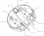
Fig. 1 is the three-dimensional structure diagram of a kind of embodiment of the utility model lower base of connector.
Fig. 2 is the shell three-dimensional structure diagram of lower base of connector among Fig. 1.
Fig. 3 is the retainer ring three-dimensional structure diagram of lower base of connector among Fig. 1.
Fig. 4 is the rear perspective structure chart of lower base of connector retainer ring among Fig. 3.
In each accompanying drawing: 10, retainer ring; 11, retainer ring core wall; 12, connect string; 14, lead; 141, hole; 20, shell; 3, compression conductive shell fragment; 31, compression conductive shell fragment terminals; 4, grounding reed; 41, ground connection terminals; 5, shell core wall.
Embodiment
Like Fig. 1, Fig. 2, Fig. 3, shown in Figure 4; A kind of embodiment of the utility model lower base of connector; A kind of lower base of connector; Two compression conductive shell fragments 3 that comprise shell 20, are connected with the external power supply both positive and negative polarity and the grounding reed 4 that is connected with the earth electrode of external power supply also comprise insulation retainer ring 10, and described shell 20 can adopt securing member or the relative socket of ultrasonic bonding mode with insulation retainer ring 10; Retainer ring 10 is provided with insulation and connects string 12; The middle part that insulation connects string 12 is provided with retainer ring core wall 11, and grounding reed 4 is installed in the back side of insulation connection string 12 between the retainer ring core wall 11, and two compression conductive shell fragments 3 separate through retainer ring core wall 11 and being installed on the front that insulation connects string 12.Thoroughly separate between the easy contact liq coupled end of ground connection terminals 41 that retainer ring core wall 11 is connected compression conductive shell fragment 3 with the external power supply both positive and negative polarity compression conductive shell fragment terminals 31, wiring reed 4 are connected with the earth electrode of extraneous power supply and compression conductive shell fragment, grounding reed 4.For being strictly on guard against contacting of grounding reed 4 and compression conductive shell fragment 3; Ensure the waterproof and the fail safe of connector; Present embodiment is employed in retainer ring 10 middle parts and is provided with insulating and is connected the lead 14 that string 12 links to each other; The middle part of lead 14 is provided with hole 141, and the coupled end of grounding reed 4 is arranged in the hole 141 of lead 14, and said shell 20 is provided with the arc shell core wall 5 that is provided with around lead 14.The staggered arc shell core wall of setting up 5 effects are in the shell 2: isolate the coupled end that two compression conductive shell fragments 3 are prone to contact liq.
Being designed with of the retainer ring 1 of the utility model is beneficial to draining, and two compression conductive shell fragments 3 and grounding reed 4 be installed on respectively insulation be connected string 12 just, the design at the back side, make the isolation of insulating fully of compression conductive shell fragment and grounding reed 4.Simultaneously after retainer ring 1 and shell 2 relative fixed; Retainer ring core wall 11 on the retainer ring 1 and the shell core wall of shell 25 form complete water proof band; Compression conductive shell fragment 3 contact liq ends are separated with compression conductive shell fragment terminals 31 fully; Make compression conductive shell fragment terminals 31, ground connection binding post 41 keep dry for a long time, electrical equipment prolongs useful life greatly.Because the formation of water proof band; The liquid that the lower base of connector water inlet gets into is separated discharge fully by the water proof band, can not be stranded in the lower base of connector again, thereby have no way of influencing conductive component and grounding reed parts electric clearance and creepage distance; Just can creepage trace yet; The danger of having stopped the circuit short circuit takes place, and fundamentally plays waterproof effect, and is more safe.
Claims (2)
1. lower base of connector; Two compression conductive shell fragments (3) that comprise shell (20), are connected and the grounding reed (4) that is connected with the earth electrode of external power supply with the external power supply both positive and negative polarity; It is characterized in that: also comprise insulation retainer ring (10); Described shell (20) and insulation retainer ring (10) socket relatively; Retainer ring (10) is provided with insulation and connects string (12); The middle part that insulation connects string (12) is provided with retainer ring core wall (11), and grounding reed (4) is installed in the back side of insulation connection string (12) between the retainer ring core wall (11), and two compression conductive shell fragments (3) separate through retainer ring core wall (11) and being installed on the front that insulation connects string (12).
2. lower base of connector according to claim 1; It is characterized in that: said retainer ring (10) middle part is provided with insulating and is connected the continuous lead (14) of string (12); The middle part of lead (14) is provided with hole (141); The coupled end of grounding reed (4) is arranged in the hole (141) of lead (14), and said shell (20) is provided with the arc shell core wall (5) that is provided with around lead (14).
Priority Applications (1)
| Application Number | Priority Date | Filing Date | Title |
|---|---|---|---|
| CN2012200600079U CN202454813U (en) | 2012-02-23 | 2012-02-23 | Connector lower seat |
Applications Claiming Priority (1)
| Application Number | Priority Date | Filing Date | Title |
|---|---|---|---|
| CN2012200600079U CN202454813U (en) | 2012-02-23 | 2012-02-23 | Connector lower seat |
Publications (1)
| Publication Number | Publication Date |
|---|---|
| CN202454813U true CN202454813U (en) | 2012-09-26 |
Family
ID=46870643
Family Applications (1)
| Application Number | Title | Priority Date | Filing Date |
|---|---|---|---|
| CN2012200600079U Expired - Fee Related CN202454813U (en) | 2012-02-23 | 2012-02-23 | Connector lower seat |
Country Status (1)
| Country | Link |
|---|---|
| CN (1) | CN202454813U (en) |
Cited By (1)
| Publication number | Priority date | Publication date | Assignee | Title |
|---|---|---|---|---|
| CN102544873A (en) * | 2012-02-23 | 2012-07-04 | 浙江家泰电器制造有限公司 | Lower seat of connector |
-
2012
- 2012-02-23 CN CN2012200600079U patent/CN202454813U/en not_active Expired - Fee Related
Cited By (2)
| Publication number | Priority date | Publication date | Assignee | Title |
|---|---|---|---|---|
| CN102544873A (en) * | 2012-02-23 | 2012-07-04 | 浙江家泰电器制造有限公司 | Lower seat of connector |
| CN102544873B (en) * | 2012-02-23 | 2014-06-04 | 浙江家泰电器制造有限公司 | Lower seat of connector |
Similar Documents
| Publication | Publication Date | Title |
|---|---|---|
| CN202474381U (en) | Food processor connector, food processor, soybean milk maker | |
| KR101604881B1 (en) | Water-proof insulation connector | |
| CN109390794A (en) | Electric connector and electric-type battery case is changed comprising it | |
| CN205985641U (en) | Detachable connector | |
| CN202333299U (en) | Rotary water-proof safety power expansion board | |
| CN201219148Y (en) | Connector assembly | |
| CN102544873B (en) | Lower seat of connector | |
| CN109193245B (en) | An anti-drop connection assembly that can be used underwater | |
| CN205621935U (en) | Rectangle heavy load connector | |
| CN201270325Y (en) | Waterproof insulation connector | |
| CN213753322U (en) | Magnetic safety socket | |
| CN205985409U (en) | Battery connecting wire | |
| CN207977509U (en) | Three balls linkage safety socket | |
| CN209216692U (en) | A transformer for preventing glue overflow | |
| CN203850180U (en) | Moisture-proof power switch | |
| CN202308576U (en) | Short-circuit resistant power supply expanding board in spite of water seepage | |
| CN102394439A (en) | Power supply expansion plate being free of short circuit in the case of water seepage | |
| CN205790650U (en) | A kind of flat water-proof connector | |
| CN205841746U (en) | A kind of sealing structure and automobile controller | |
| CN108232604A (en) | Three balls linkage safety socket | |
| CN202423691U (en) | Waterproof power expansion board capable of disconnecting safely | |
| CN102361316B (en) | Sealing insulation structure of electric heating floor conductor | |
| CN214542629U (en) | Torsion spring for large-current connector contact | |
| CN204558775U (en) | A kind of electric connector | |
| CN213401598U (en) | Lower seat of connector |
Legal Events
| Date | Code | Title | Description |
|---|---|---|---|
| C14 | Grant of patent or utility model | ||
| GR01 | Patent grant | ||
| CF01 | Termination of patent right due to non-payment of annual fee |
Granted publication date: 20120926 Termination date: 20150223 |
|
| EXPY | Termination of patent right or utility model |