CN202439192U - Material head clamping and demolding device installed at end part of manipulator of injection molding machine - Google Patents
Material head clamping and demolding device installed at end part of manipulator of injection molding machine Download PDFInfo
- Publication number
- CN202439192U CN202439192U CN2012200205489U CN201220020548U CN202439192U CN 202439192 U CN202439192 U CN 202439192U CN 2012200205489 U CN2012200205489 U CN 2012200205489U CN 201220020548 U CN201220020548 U CN 201220020548U CN 202439192 U CN202439192 U CN 202439192U
- Authority
- CN
- China
- Prior art keywords
- main frame
- stub bar
- cylinder
- manipulator
- product
- Prior art date
- Legal status (The legal status is an assumption and is not a legal conclusion. Google has not performed a legal analysis and makes no representation as to the accuracy of the status listed.)
- Expired - Lifetime
Links
Images


Landscapes
- Moulds For Moulding Plastics Or The Like (AREA)
Abstract
The utility model discloses a material head clamping and de-molding device installed at an end part of a manipulator of an injection molding machine. The material head clamping and de-molding device comprises a main frame; an upper end surface of the main frame is connected with the end part of the manipulator; a groove for accommodating a material head is arranged at the centre of a lower end surface of the main frame; one side of the groove is provided with a material head clamping plate driven by a first air cylinder; the first air cylinder is fixed on the main frame; the other side of the groove is provided with a product fixing plate driven by a second air cylinder; the second air cylinder is fixed on a rotary frame which is pivoted with the main frame; the rotary frame is driven by a third air cylinder to rotate; one end of the third air cylinder is pivoted with the main frame and the other end is pivoted with the rotary frame; the main frame is further provided with a discharge head blowing pipe. The material head clamping and de-molding device installed at the end part of the manipulator of the injection molding machine enables an injection-molded product to be automatically separated from the material head, so that the manpower is saved and the production efficiency is improved; moreover, the product and the material head are placed separately by the matching of the manipulator, so that the product is protected, a working procedure of separating the product from the material head is saved, and the production efficiency is further improved.
Description
Technical field
The utility model relates to injection machine and uses the manipulator technical field, especially a kind ofly is loaded on the material folding of manipulator of injection machine end and takes off the stub bar device.
Background technology
In the production process of injecting products; Most of injecting products link together producing back stub bar and product; The injecting products of producing so just needs manpower to remove manually to break off with the fingers and thumb the fracture head and difference is placed; Because the output of injecting products is general bigger, will increase a lot of human costs, also influence production efficiency and product quality simultaneously.
The automatic disconnecting device of existing injection moulding stub bar generally all is arranged in the mould; As on August 11st, 2010 a disclosed patent No. be that ZL201020128330.6, name are called the utility model patent of " a kind of shearing device of injection moulding stub bar "; Its stub bar shearing device is arranged in the mould; To the automatic pruning of stub bar, the structure of this frame mode one side mould is high than complicacy and cost, increases injection cycle on the other hand in the time of can realizing molding; Influence production efficiency, also be difficult to make product and stub bar placed apart.
The utility model content
The technical problem that the utility model will solve provides and a kind ofly is loaded on the material folding of manipulator of injection machine end and takes off the stub bar device, and injecting products and stub bar are broken away from automatically, saves manpower, enhances productivity; And cooperate through manipulator to make product and stub bar placed apart, both protected product, also save product and stub bar separation procedure, further enhance productivity.
For achieving the above object, the technical scheme of the utility model is: a kind ofly be loaded on the material folding of manipulator of injection machine end and take off the stub bar device, comprise main frame; The upper surface of main frame is connected with robot end; The centre of main frame lower surface is provided with the groove that holds stub bar, and a side of groove is provided with the stub bar clamping plate by first air cylinder driven, and first cylinder is fixed on the main frame; The opposite side of groove is provided with the product fixed head by second air cylinder driven; Second cylinder is fixed on the swivel mount that is articulated with main frame, and swivel mount is rotated by the 3rd air cylinder driven, and an end and the main frame of the 3rd cylinder is articulated, the other end and swivel mount are articulated.
Further, also be provided with on the described main frame and unload the stub bar gas blow pipe, guarantee that stub bar can break away from the middle groove of main frame.
Further, a fixing push pedal is provided with a track on main frame on the piston rod of first cylinder, and described push pedal is connected with the stub bar clamping plate again, and described stub bar clamping plate moves along the track of main frame, makes that moving of stub bar clamping plate is more reliable.
Further; Described product fixed head can be connected with the piston rod of second cylinder with respect to the pushing block of swivel mount rotation through one; One end and the swivel mount of said pushing block is articulated, the other end and product fixed head fix; The piston rod of the middle part of said pushing block and second cylinder is articulated, and further facilitates product and draws off the product fixed head.
Further again, the central point of the rotation of described swivel mount is arranged on the cast gate center between stub bar and the product, and more convenient stub bar and product break away from.
Further again; Said first cylinder and stub bar clamping plate respectively have two places, diagonal angle that are arranged on main frame; Described second cylinder, product fixed head, swivel mount and the 3rd cylinder respectively have two to be arranged on another place, diagonal angle of main frame, further improve the disengaging efficient of stub bar and product.
The utility model is because the centre of main frame lower surface is provided with the groove that holds stub bar, and a side of groove is provided with the stub bar clamping plate by first air cylinder driven, after stub bar gets into groove; Move the stub bar clamping plate and just can clamp stub bar, the opposite side at groove is provided with the product fixed head by second air cylinder driven simultaneously, and the mobile product fixed head just can be clamped product product is fixed; Second cylinder is fixed on again on the swivel mount that is articulated with main frame; Swivel mount is rotated by the 3rd air cylinder driven, and swivel mount just drives second cylinder when rotating and the product fixed head is done bending action, and product and stub bar are broken away from; Save manpower, enhance productivity; Move to diverse location through manipulator again and just can separately be discharged at product and stub bar on the different positions, both protected product, also save product and stub bar separation procedure, further enhance productivity.
Description of drawings
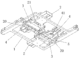
Fig. 1 is the utility model vertical view.
Fig. 2 is the utility model upward view.
Fig. 3 is the utility model top perspective view.
Fig. 4 is the utility model face upwarding stereogram.
Fig. 5 is the vertical view of a kind of product of the utility model clamping and stub bar connection status.
Fig. 6 is the stereogram of Fig. 5.
Fig. 7 is the utility model material folding state face upwarding stereogram.
Fig. 8 is the face upwarding stereogram that the utility model takes off the stub bar state.
The specific embodiment
Below in conjunction with accompanying drawing and concrete embodiment the utility model is done further explain.
Fig. 1 is to shown in Figure 6, a kind ofly is loaded on the material folding of manipulator of injection machine end and takes off the stub bar device, comprises main frame 1; The upper surface 11 of main frame 1 is connected with robot end; The centre of main frame 1 lower surface is provided with the groove 12 that holds stub bar 10, and a side of groove 12 is provided with stub bar clamping plate 3, the first cylinders 2 that driven by first cylinder 2 and is fixed on the main frame 1; The opposite side of groove 12 is provided with the product fixed head 5 that is driven by second cylinder 4; Second cylinder 4 is fixed on the swivel mount 6 that is articulated with main frame 1, and swivel mount 6 is by the 3rd cylinder 7 driven in rotation, and an end and the main frame 1 of the 3rd cylinder 7 is articulated, the other end and swivel mount 6 are articulated.
Also be provided with on the described main frame 1 and unload stub bar gas blow pipe (not shown).
A fixing push pedal 21 is provided with a track 13 on main frame 1 on the piston rod of first cylinder 2, and described push pedal 21 is connected with stub bar clamping plate 3 again, and described stub bar clamping plate 3 moves along the track 13 of main frame 1.
Described product fixed head 5 can be connected with the piston rod of second cylinder 4 with respect to the pushing block 41 of swivel mount 6 rotations through one; One end and the swivel mount 6 of said pushing block 41 is articulated, the other end and product fixed head 5 fix, and the piston rod of the middle part of said pushing block 41 and second cylinder 4 is articulated.
The central point of the rotation of preferred described swivel mount 6 is arranged on the cast gate center between stub bar 10 and the product 20.
Said first cylinder 2, push pedal 21, track 13 and stub bar clamping plate 3 respectively have two places, diagonal angle that are arranged on main frame 1, and described second cylinder 4, pushing block 41, product fixed head 5, swivel mount 6 and the 3rd cylinder 7 respectively have two to be arranged on main frame 1 another place, diagonal angle.
The workflow of the utility model is following:
Shown in Fig. 7 and top accompanying drawing; Product 20 injection mouldings are accomplished, mold open, and this moment, product 20 linked together with stub bar 10; The descending drive main frame 1 of manipulator gets in the mould; Mould ejects product 20 and stub bar 10 and pushes up stub bar 10 in the middle groove 12 in main frame 1 lower surface, and 2 actions of first cylinder make stub bar clamping plate 3 move a stub bar 10 toward groove 12 directions through push pedal 21 and clamp, second cylinder, 4 actions then; Through pushing block 41 product fixed head 5 is moved toward groove 12 directions and clamp product 20, this moment, stub bar 10 was all fixed with product 20.
Shown in Fig. 8 and top accompanying drawing; Manipulator is up, leaves mould arrival product and accepts the basket top and go downwards to most proximal end, and 7 actions of the 3rd cylinder make swivel mount 6 rotations; Swivel mount 6 drives second cylinder 4 and does bending action with product fixed head 5; Stub bar 10 and product 20 are broken away from, and then 4 actions of second cylinder make 5 rotations while retreating of product fixed head through pushing block 41, and product 20 just drops to product naturally through deadweight and accepts in the basket; Stub bar 10 was gone back quilting head clamping plate 3 and was clipped in the groove 12 in the middle of the main frame 1 this moment; Next manipulator moves to stub bar again and accepts the basket top; The action of first cylinder 2 makes stub bar clamping plate 3 pushers through push pedal 21, is located at stub bar gas blow pipe on the main frame 1 simultaneously and aims at stub bar 10 and blow and blow to stub bar to stub bar 10 and accept in the basket; Accomplish a circulation, stub bar 10 is broken away from automatically with product 20 and is placed on the different positions like this.
Below only be preferred embodiment of the utility model, the change that those skilled in the art does to be equal to by claim all falls into the protection domain of this case.
Claims (6)
1. one kind is loaded on the material folding of manipulator of injection machine end and takes off the stub bar device; Comprise main frame, the upper surface of main frame is connected with robot end, it is characterized in that: the centre of main frame lower surface is provided with the groove that holds stub bar; One side of groove is provided with the stub bar clamping plate by first air cylinder driven; First cylinder is fixed on the main frame, and the opposite side of groove is provided with the product fixed head by second air cylinder driven, and second cylinder is fixed on the swivel mount that is articulated with main frame; Swivel mount is rotated by the 3rd air cylinder driven, and an end and the main frame of the 3rd cylinder is articulated, the other end and swivel mount are articulated.
2. according to claim 1ly a kind ofly be loaded on the material folding of manipulator of injection machine end and take off the stub bar device, it is characterized in that: also be provided with on the described main frame and unload the stub bar gas blow pipe.
3. according to claim 1ly a kind ofly be loaded on the material folding of manipulator of injection machine end and take off the stub bar device; It is characterized in that: a fixing push pedal on the piston rod of first cylinder; One track is set on main frame; Described push pedal is connected with the stub bar clamping plate again, and described stub bar clamping plate moves along the track of main frame.
4. according to claim 1ly a kind ofly be loaded on the material folding of manipulator of injection machine end and take off the stub bar device; It is characterized in that: described product fixed head can be connected with the piston rod of second cylinder with respect to the pushing block of swivel mount rotation through one; One end and the swivel mount of said pushing block is articulated, the other end and product fixed head fix, and the piston rod of the middle part of said pushing block and second cylinder is articulated.
5. each describedly a kind ofly is loaded on the material folding of manipulator of injection machine end and takes off the stub bar device according to claim 1 to 4, and it is characterized in that: the central point of the rotation of described swivel mount is arranged on the cast gate center between stub bar and the product.
6. each describedly a kind ofly is loaded on the material folding of manipulator of injection machine end and takes off the stub bar device according to claim 1 to 4; It is characterized in that: said first cylinder and stub bar clamping plate respectively have two places, diagonal angle that are arranged on main frame, and described second cylinder, product fixed head, swivel mount and the 3rd cylinder respectively have two to be arranged on another place, diagonal angle of main frame.
Priority Applications (1)
| Application Number | Priority Date | Filing Date | Title |
|---|---|---|---|
| CN2012200205489U CN202439192U (en) | 2012-01-17 | 2012-01-17 | Material head clamping and demolding device installed at end part of manipulator of injection molding machine |
Applications Claiming Priority (1)
| Application Number | Priority Date | Filing Date | Title |
|---|---|---|---|
| CN2012200205489U CN202439192U (en) | 2012-01-17 | 2012-01-17 | Material head clamping and demolding device installed at end part of manipulator of injection molding machine |
Publications (1)
| Publication Number | Publication Date |
|---|---|
| CN202439192U true CN202439192U (en) | 2012-09-19 |
Family
ID=46820646
Family Applications (1)
| Application Number | Title | Priority Date | Filing Date |
|---|---|---|---|
| CN2012200205489U Expired - Lifetime CN202439192U (en) | 2012-01-17 | 2012-01-17 | Material head clamping and demolding device installed at end part of manipulator of injection molding machine |
Country Status (1)
| Country | Link |
|---|---|
| CN (1) | CN202439192U (en) |
Cited By (7)
| Publication number | Priority date | Publication date | Assignee | Title |
|---|---|---|---|---|
| CN104118092A (en) * | 2014-07-31 | 2014-10-29 | 宁波问鼎机器人有限公司 | Automatic disconnecting and sub-packaging machine for injection molded products |
| CN104260295A (en) * | 2014-08-06 | 2015-01-07 | 孙昌锡 | Automatic mold opening machine for turntable shoe making machine |
| CN104369206A (en) * | 2014-11-11 | 2015-02-25 | 昆山三多乐电子有限公司 | Regulating valve gate automatic picking, placing and shearing device |
| CN106738676A (en) * | 2017-03-13 | 2017-05-31 | 东莞市宜曼洲电子科技有限公司 | Product taking mechanism of multi-cavity mold and multi-cavity mold |
| CN108437380A (en) * | 2018-04-17 | 2018-08-24 | 天津市中环三峰电子有限公司 | A kind of moulding cast gate splits equipment automatically |
| CN108481690A (en) * | 2018-04-17 | 2018-09-04 | 天津市中环三峰电子有限公司 | A kind of moulding cast gate detachment device |
| CN115195165A (en) * | 2022-08-02 | 2022-10-18 | 深圳市贝利医疗设备有限公司 | Device for removing waste on plate |
-
2012
- 2012-01-17 CN CN2012200205489U patent/CN202439192U/en not_active Expired - Lifetime
Cited By (13)
| Publication number | Priority date | Publication date | Assignee | Title |
|---|---|---|---|---|
| CN104118092A (en) * | 2014-07-31 | 2014-10-29 | 宁波问鼎机器人有限公司 | Automatic disconnecting and sub-packaging machine for injection molded products |
| CN104118092B (en) * | 2014-07-31 | 2016-09-07 | 宁波问鼎机器人有限公司 | A kind of injection-molded item automatic cutting racking machine |
| CN104260295A (en) * | 2014-08-06 | 2015-01-07 | 孙昌锡 | Automatic mold opening machine for turntable shoe making machine |
| CN104260295B (en) * | 2014-08-06 | 2016-09-28 | 孙昌锡 | A kind of automatic mould opening machine for rotating disk shoes making machine |
| CN104369206A (en) * | 2014-11-11 | 2015-02-25 | 昆山三多乐电子有限公司 | Regulating valve gate automatic picking, placing and shearing device |
| CN104369206B (en) * | 2014-11-11 | 2016-05-11 | 昆山三多乐电子有限公司 | Control valve is cut mouth of a river automation and is picked and placeed and shear |
| CN106738676A (en) * | 2017-03-13 | 2017-05-31 | 东莞市宜曼洲电子科技有限公司 | Product taking mechanism of multi-cavity mold and multi-cavity mold |
| CN108437380A (en) * | 2018-04-17 | 2018-08-24 | 天津市中环三峰电子有限公司 | A kind of moulding cast gate splits equipment automatically |
| CN108481690A (en) * | 2018-04-17 | 2018-09-04 | 天津市中环三峰电子有限公司 | A kind of moulding cast gate detachment device |
| CN108481690B (en) * | 2018-04-17 | 2024-04-16 | 天津市中环三峰电子有限公司 | Injection molding runner splitting device |
| CN108437380B (en) * | 2018-04-17 | 2024-04-16 | 天津市中环三峰电子有限公司 | An automatic splitting device for injection molded parts gate |
| CN115195165A (en) * | 2022-08-02 | 2022-10-18 | 深圳市贝利医疗设备有限公司 | Device for removing waste on plate |
| CN115195165B (en) * | 2022-08-02 | 2023-12-22 | 深圳市贝利医疗设备有限公司 | A device for removing scrap from sheet metal |
Similar Documents
| Publication | Publication Date | Title |
|---|---|---|
| CN101863097B (en) | Automatic glass separating device | |
| CN102114696A (en) | Method for shearing water gap and device for implementing method | |
| CN201792457U (en) | Plastic mould capable of demoulding quickly | |
| CN203438513U (en) | Bumper taking device | |
| CN203004395U (en) | Automatic material clamping and discharging device of powder pressing machine | |
| CN201783604U (en) | Forming machine for jewelry with semicircular ends | |
| CN103586352B (en) | Be convenient to car band skylight top cover and switch the mould structure produced without skylight top cover | |
| CN209955234U (en) | Multi-gripper injection molding machine manipulator | |
| CN103372948B (en) | Full-automatic double position vertical and horizontal injection machine | |
| CN106346796A (en) | A method of using an automatic injection molding and assembly device | |
| CN207465800U (en) | A manipulator specially designed for injection molding machines to prevent pinch damage and easily pick up parts | |
| CN201841665U (en) | Plastic product cutting device for plastic suction machine | |
| CN205416265U (en) | Manipulator on tableware automated production equipment | |
| CN210148652U (en) | Automatic unloading of injection moulding product is cuted integration equipment | |
| CN204148473U (en) | Automatic separation extractor shedding mechanism | |
| CN212291905U (en) | Fully automatic conveying mechanism | |
| CN208682040U (en) | It is a kind of for the rotary automatic clamping device with bent angle moulding | |
| CN102601980B (en) | Pneumatic clamping device for blowing mould | |
| CN210940187U (en) | Mold clamping and cutting device | |
| CN203726765U (en) | Clamping mechanism for bottle blank tail shearing machine | |
| CN202244188U (en) | Can suction mechanism | |
| CN209466625U (en) | A kind of injection molding pick-and-place fixture | |
| CN201728787U (en) | Automatic glass opening device | |
| CN105775269A (en) | Automatic folding machine for heat-resistant polylactic acid nano-composite tableware | |
| CN2625138Y (en) | Automatic demould die |
Legal Events
| Date | Code | Title | Description |
|---|---|---|---|
| C14 | Grant of patent or utility model | ||
| GR01 | Patent grant | ||
| CX01 | Expiry of patent term | ||
| CX01 | Expiry of patent term |
Granted publication date: 20120919 |