CN202411134U - Hot extrusion die allowing people to take materials conveniently - Google Patents
Hot extrusion die allowing people to take materials conveniently Download PDFInfo
- Publication number
- CN202411134U CN202411134U CN2011205293782U CN201120529378U CN202411134U CN 202411134 U CN202411134 U CN 202411134U CN 2011205293782 U CN2011205293782 U CN 2011205293782U CN 201120529378 U CN201120529378 U CN 201120529378U CN 202411134 U CN202411134 U CN 202411134U
- Authority
- CN
- China
- Prior art keywords
- die
- hole
- extrusion
- punch
- positioning block
- Prior art date
- Legal status (The legal status is an assumption and is not a legal conclusion. Google has not performed a legal analysis and makes no representation as to the accuracy of the status listed.)
- Expired - Fee Related
Links
- 238000001192 hot extrusion Methods 0.000 title claims abstract description 8
- 239000000463 material Substances 0.000 title claims abstract description 8
- 238000001125 extrusion Methods 0.000 claims abstract description 35
- 238000009415 formwork Methods 0.000 claims abstract description 6
- 238000000034 method Methods 0.000 description 4
- FYYHWMGAXLPEAU-UHFFFAOYSA-N Magnesium Chemical compound [Mg] FYYHWMGAXLPEAU-UHFFFAOYSA-N 0.000 description 3
- XAGFODPZIPBFFR-UHFFFAOYSA-N aluminium Chemical compound [Al] XAGFODPZIPBFFR-UHFFFAOYSA-N 0.000 description 3
- 229910052782 aluminium Inorganic materials 0.000 description 3
- 229910052749 magnesium Inorganic materials 0.000 description 3
- 239000011777 magnesium Substances 0.000 description 3
- 238000004519 manufacturing process Methods 0.000 description 3
- 229910021652 non-ferrous alloy Inorganic materials 0.000 description 3
- 229910000838 Al alloy Inorganic materials 0.000 description 2
- 238000010438 heat treatment Methods 0.000 description 2
- 239000012778 molding material Substances 0.000 description 2
- 229910000881 Cu alloy Inorganic materials 0.000 description 1
- 229910000861 Mg alloy Inorganic materials 0.000 description 1
- 229910045601 alloy Inorganic materials 0.000 description 1
- 239000000956 alloy Substances 0.000 description 1
- 230000009286 beneficial effect Effects 0.000 description 1
- 238000010586 diagram Methods 0.000 description 1
- 238000007599 discharging Methods 0.000 description 1
- 238000003825 pressing Methods 0.000 description 1
Images



Landscapes
- Extrusion Of Metal (AREA)
Abstract
一种便于取料热挤压模具,它包括凸模和凹模两个部分,所述凸模部分包括通过凸模固定板安装在上模板底面上的挤压凸模;所述凹模部分包括加工有中心通孔的下模板,固定安装在下模板上方的压模固定板,在压模固定板上由上至下依次加工有圆形凹槽、横截面呈矩形结构的纵向凹槽,在纵向凹槽的底面设置有与下模板中心通孔共轴线、且孔径相等的通孔,在所述纵向凹槽内放置有厚度与纵向凹槽槽深相等的推拉滑块,在所述圆形凹槽的上方座放有空心柱形结构的凹模定位块,所述凹模定位块腔体的上部与挤压凸模相配合,在凹模定位块腔体的下部腔体内放置有挤压凹模,挤压凹模的底面座放在推拉滑块的上方,在推拉滑块上加工有连通挤压凹模模腔和纵向凹槽的底面设置的通孔的孔。

A kind of hot extrusion mold that is convenient to take material, it comprises two parts of punch and die, and described punch part comprises the extruding punch that is installed on the bottom surface of upper formwork through punch fixing plate; Described die part includes The lower formwork with a central through hole is processed, and the die fixing plate fixedly installed above the lower formwork. On the die fixing plate, circular grooves and longitudinal grooves with a rectangular cross-section are sequentially processed from top to bottom. The bottom surface of the groove is provided with a through hole that is coaxial with the central through hole of the lower template and has an equal aperture. A push-pull slider with a thickness equal to the depth of the longitudinal groove is placed in the longitudinal groove. A concave die positioning block with a hollow cylindrical structure is placed above the groove. The upper part of the die positioning block cavity is matched with the extrusion punch, and an extrusion concave is placed in the lower cavity of the die positioning block cavity. Die, the bottom surface seat of the extrusion die is placed on the top of the push-pull slider, and the push-pull slider is processed with a hole connecting the cavity of the extrusion die and the through hole arranged on the bottom surface of the longitudinal groove.
Description
技术领域 technical field
本实用新型涉及一种挤压模具,具体涉及一种生产铝合金、镁合金和铜合金等有色合金棒材或型材的便于取料热挤压模具。 The utility model relates to an extrusion die, in particular to a hot extrusion die for producing aluminum alloy, magnesium alloy, copper alloy and other non-ferrous alloy rods or profiles. the
背景技术 Background technique
现有生产铝、镁等有色合金的模具主要由凸模和整体式的凹模组成,取料不方便,且在生产不同形状和尺寸的铝合金产品时,整体式凹模的更换成本高,凹模的装卸复杂。 Existing molds for the production of non-ferrous alloys such as aluminum and magnesium are mainly composed of punches and integral dies, which are inconvenient to take out materials, and when producing aluminum alloy products of different shapes and sizes, the cost of replacing the integral dies is high. The loading and unloading of the die is complicated. the
发明内容 Contents of the invention
本实用新型的目的正是针对上述现有技术中所存在的不足之处而提供一种结构简单,可通过更换工作模块生产多种形状和尺寸的产品,且易于挤压成型和方便取料的铝、镁等有色合金的便于取料热挤压模具。 The purpose of this utility model is to provide a simple structure for the shortcomings of the above-mentioned prior art, which can produce products of various shapes and sizes by replacing the working modules, and is easy to extrude and convenient to take materials. Aluminum, magnesium and other non-ferrous alloys are easy to take out hot extrusion dies. the
本实用新型的目的可通过下述技术措施来实现: The purpose of this utility model can be realized by following technical measures:
本实用新型的便于取料热挤压模具包括凸模和凹模两个部分,所述凸模部分包括通过凸模固定板安装在上模板底面上的挤压凸模;所述凹模部分包括加工有中心通孔的下模板,固定安装在下模板上方的压模固定板,在压模固定板上由上至下依次加工有圆形凹槽、横截面呈矩形结构的纵向凹槽,在纵向凹槽的底面设置有与下模板中心通孔共轴线、且孔径相等的通孔,在所述纵向凹槽内放置有厚度与纵向凹槽槽深相等的推拉滑块,在所述圆形凹槽的上方座放有空心柱形结构的凹模定位块,所述凹模定位块腔体的上部与挤压凸模相配合,在凹模定位块腔体的下部腔体内放置有挤压凹模,挤压凹模的底面座放在推拉滑块的上方,在推拉滑块上加工有连通挤压凹模模腔和纵向凹槽的底面设置的通孔的孔;环绕凹模定位块外壁的中上部设置有加热器。 The utility model is convenient to take material hot extrusion die and comprises two parts of punch and die, and described punch part comprises the extruding punch that is installed on the upper template bottom surface by punch fixing plate; Described die part includes The lower formwork with a central through hole is processed, and the die fixing plate fixedly installed above the lower formwork. On the die fixing plate, circular grooves and longitudinal grooves with a rectangular cross-section are sequentially processed from top to bottom. The bottom surface of the groove is provided with a through hole that is coaxial with the central through hole of the lower template and has an equal aperture. A push-pull slider with a thickness equal to the depth of the longitudinal groove is placed in the longitudinal groove. A concave die positioning block with a hollow cylindrical structure is placed above the groove. The upper part of the cavity of the die positioning block is matched with the extrusion punch, and an extrusion concave is placed in the lower cavity of the cavity of the die positioning block. Die, the bottom surface seat of the extrusion die is placed above the push-pull slider, and the push-pull slider is processed with a hole connecting the cavity of the extrusion die and the bottom surface of the longitudinal groove; the outer wall of the positioning block surrounding the die The middle and upper part is provided with a heater.
本实用新型在所述下模板周边设置有与上模板周边设置的导套孔相配合的导柱。 In the utility model, a guide column is arranged on the periphery of the lower template to match the guide sleeve hole provided on the periphery of the upper template. the
本实用新型的有益效果如下: The beneficial effects of the utility model are as follows:
本实用新型与现有技术相比具有下述特点:凹模的工作模块可根据生产的需要进行更换,可生产多种铝镁等合金型材和棒材;凹模在挤压过程中,可由滑块对其支撑,并且挤压的成型料可顺利通过滑块上设置的通孔;挤压结束后,可方便地实现落料取料,推拉模块能缩短出料时间,大大提高生产效率;挤压凹模由压模固定板和凹模定位块固定,安装拆卸方便,定位准确;加热装置设置在凹模固定块外壁的中上部,加热方法简单有效。 Compared with the prior art, the utility model has the following characteristics: the working module of the die can be replaced according to the needs of production, and can produce various alloy profiles and rods such as aluminum and magnesium; The block supports it, and the extruded molding material can smoothly pass through the through hole set on the slider; after the extrusion is completed, it can conveniently realize the blanking and retrieving of the material, and the push-pull module can shorten the discharging time and greatly improve the production efficiency; The pressing die is fixed by the die fixing plate and the die positioning block, which is convenient to install and disassemble, and the positioning is accurate; the heating device is set on the middle and upper part of the outer wall of the die fixing block, and the heating method is simple and effective.
附图说明 Description of drawings
图1是本实用新型正剖面结构示意图(图2的A-A剖视图)。 Fig. 1 is a schematic diagram of the front section structure of the utility model (A-A sectional view of Fig. 2). the
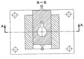
图2是图1的B-B剖视图(滑块8上设置的圆柱形通孔与挤压凹模7的中心孔的位置处于错位状态)。
Fig. 2 is a B-B cross-sectional view of Fig. 1 (the position of the cylindrical through hole provided on the
图3是图1的B-B剖视图(滑块8上设置的圆柱形通孔与挤压凹模7的中心孔的位置处于同心状态)。
Fig. 3 is a B-B sectional view of Fig. 1 (the position of the cylindrical through hole provided on the
图4是挤压凹模的剖视图。 Fig. 4 is a sectional view of an extrusion die. the
具体实施方式 Detailed ways
本实用新型以下将结合实施例(附图)作进一步描述: The utility model will be further described below in conjunction with embodiment (accompanying drawing):
如图1、2所示,本实用新型的便于取料热挤压模具包括凸模和凹模两个部分,所述凸模部分包括通过凸模固定板2安装在上模板1底面上的挤压凸模3;所述凹模部分包括加工有中心通孔的下模板10,固定安装在下模板10上方的压模固定板4,在压模固定板上由上至下依次加工有圆形凹槽、横截面呈矩形结构的纵向凹槽,在纵向凹槽的底面设置有与下模板10中心通孔共轴线、且孔径相等的通孔,在所述纵向凹槽内放置有厚度与纵向凹槽槽深相等的推拉滑块8,在所述圆形凹槽的上方座放有空心柱形结构的凹模定位块5,所述凹模定位块腔体的上部与挤压凸模3相配合,在凹模定位块腔体的下部腔体内放置有挤压凹模7(参见图3),挤压凹模7的底面座放在推拉滑块8的上方,在推拉滑块8上加工有连通挤压凹模7 模腔和纵向凹槽的底面设置的通孔的孔;环绕凹模定位块5外壁的中上部设置有加热器6。本实用新型在所述下模板10周边设置有与上模板周边设置的导套相孔11配合的导柱9。
As shown in Figures 1 and 2, the utility model’s easy-to-take hot extrusion die includes two parts: a punch and a die. Press the
更具体说:本实用新型中所示凹模定位块5的上部圆形内孔用于放置挤压坯料;挤压凹模7由方形的推拉滑块8支撑,滑块8安放在压模固定板4的纵向凹槽内,两者相互配合使得滑块8可在压模固定板4内部进行纵向往复运动(其结构见图2);挤压凹模7放置在凹模定位块5的内腔内,并使得在挤压凹模7上部的台阶与凹模定位块5内腔的台阶相互配合的情况下,使挤压凹模7与凹模定位块5的下部端面齐平,同时使滑块8与挤压凹模7相互接触;导柱9和导套孔11的配合起到导向作用。
More specifically: the upper circular inner hole of the
在挤压过程中,模块8的位置如图2所示,成型料可通过滑块8上设置的与圆柱形通孔相连通的侧置条形槽孔,挤压过程结束后,推拉模块8在拉力的作用下到达如图3所示的位置,即滑块8上设置的与圆柱形通孔与挤压凹模7的中心孔的位置同心,且其直径稍大于挤压凹模7的外径,则工件就能通过滑块8的圆柱形通孔顺利的下落,挤压凹模7下落后,则推拉模块8再推到如图2所示位置,把取完余料的挤压凹模7放置于凹模定位块5的内腔,则可实现循环工作。挤压凹模7的内腔截面可以是圆形或其它型材截面。
During the extrusion process, the position of the
Claims (2)
Priority Applications (1)
| Application Number | Priority Date | Filing Date | Title |
|---|---|---|---|
| CN2011205293782U CN202411134U (en) | 2011-12-17 | 2011-12-17 | Hot extrusion die allowing people to take materials conveniently |
Applications Claiming Priority (1)
| Application Number | Priority Date | Filing Date | Title |
|---|---|---|---|
| CN2011205293782U CN202411134U (en) | 2011-12-17 | 2011-12-17 | Hot extrusion die allowing people to take materials conveniently |
Publications (1)
| Publication Number | Publication Date |
|---|---|
| CN202411134U true CN202411134U (en) | 2012-09-05 |
Family
ID=46735931
Family Applications (1)
| Application Number | Title | Priority Date | Filing Date |
|---|---|---|---|
| CN2011205293782U Expired - Fee Related CN202411134U (en) | 2011-12-17 | 2011-12-17 | Hot extrusion die allowing people to take materials conveniently |
Country Status (1)
| Country | Link |
|---|---|
| CN (1) | CN202411134U (en) |
Cited By (2)
| Publication number | Priority date | Publication date | Assignee | Title |
|---|---|---|---|---|
| CN102989808A (en) * | 2012-11-23 | 2013-03-27 | 中国航空工业集团公司北京航空材料研究院 | TiAl-based alloy extruding mould |
| CN109719206A (en) * | 2019-01-04 | 2019-05-07 | 哈尔滨工业大学(威海) | A kind of bimetallic microchannel extrusion cladding and forming integrated device and method |
-
2011
- 2011-12-17 CN CN2011205293782U patent/CN202411134U/en not_active Expired - Fee Related
Cited By (3)
| Publication number | Priority date | Publication date | Assignee | Title |
|---|---|---|---|---|
| CN102989808A (en) * | 2012-11-23 | 2013-03-27 | 中国航空工业集团公司北京航空材料研究院 | TiAl-based alloy extruding mould |
| CN109719206A (en) * | 2019-01-04 | 2019-05-07 | 哈尔滨工业大学(威海) | A kind of bimetallic microchannel extrusion cladding and forming integrated device and method |
| CN109719206B (en) * | 2019-01-04 | 2020-09-18 | 哈尔滨工业大学(威海) | Bimetal microchannel extrusion compounding and forming integrated device and method |
Similar Documents
| Publication | Publication Date | Title |
|---|---|---|
| CN101332476B (en) | A precision extrusion forming method and special mold for thin-walled long tubular part blank | |
| CN101829698A (en) | Extrusion forming process of thin-wall long pipe-shaped part blank with flange and mould | |
| CN110695111B (en) | A radial-reverse combined extrusion forming die for thin-walled cylindrical parts with outer bosses | |
| CN103350178A (en) | Sliding locking device of valve body forging mould | |
| CN101773975B (en) | Board upsetting and shaping die | |
| CN102107230B (en) | Shaping device for preparing bent tube by virtue of differential-velocity extrusion of dual male dies | |
| CN203470676U (en) | Concave die floating stamping device for multi-station die | |
| CN202591504U (en) | Wheel hub flashless precise forging die | |
| CN204912647U (en) | Bearing inner race forges direction mould | |
| CN204867111U (en) | Thin wall spare side opening turn -ups forming die | |
| CN104289542A (en) | Forming method for shaft component with flange | |
| CN212945219U (en) | Titanium alloy bowl form part forging and pressing mould | |
| CN202052787U (en) | Backward extrusion molding device for large cup-shaped piece | |
| CN212371084U (en) | Forging forming device for excavator flange | |
| CN201603812U (en) | A compound forming mold | |
| CN201659245U (en) | A sheet metal upsetting die | |
| CN104190836A (en) | Automatic upsetting and rounding device for wrapped shaft sleeve | |
| CN104552575B (en) | A kind of revolving body ceramic member particular manufacturing craft with degree of depth blind hole and using method | |
| CN103537505B (en) | A kind of axial workpiece mold for extruding and forming and extrusion forming method | |
| CN102228942A (en) | Semi-solid metal micro-thixoforming device with automatic mould emptier | |
| CN202438564U (en) | Hot extrusion mold convenient to disassemble and assemble | |
| CN202079192U (en) | Semisolid metal micro-thixoforming device with automatic demoulding mechanism | |
| CN103335628B (en) | A kind of measurement apparatus of deformation of cylindrical blank | |
| CN110293142B (en) | Die for copper alloy semi-solid extrusion pipe | |
| CN207857548U (en) | A kind of yoke cold reducing extrusion die |
Legal Events
| Date | Code | Title | Description |
|---|---|---|---|
| C14 | Grant of patent or utility model | ||
| GR01 | Patent grant | ||
| CF01 | Termination of patent right due to non-payment of annual fee |
Granted publication date: 20120905 Termination date: 20141217 |
|
| EXPY | Termination of patent right or utility model |