CN202398514U - Excitation device with single-axis linear motion track - Google Patents
Excitation device with single-axis linear motion track Download PDFInfo
- Publication number
- CN202398514U CN202398514U CN2012200206975U CN201220020697U CN202398514U CN 202398514 U CN202398514 U CN 202398514U CN 2012200206975 U CN2012200206975 U CN 2012200206975U CN 201220020697 U CN201220020697 U CN 201220020697U CN 202398514 U CN202398514 U CN 202398514U
- Authority
- CN
- China
- Prior art keywords
- base
- spring
- arc
- track
- fixed
- Prior art date
- Legal status (The legal status is an assumption and is not a legal conclusion. Google has not performed a legal analysis and makes no representation as to the accuracy of the status listed.)
- Expired - Fee Related
Links
Images


Landscapes
- Apparatuses For Generation Of Mechanical Vibrations (AREA)
Abstract
本实用新型公开了一种单轴直线运动轨迹激振装置,包括振动箱体、底座和偏心轴,偏心轴设置在振动箱体上;所述的振动箱体和底座之间的四角上分别设置有一变轨机构,所述变轨机构包括变轨杆、弹簧、弹簧座和支撑轴;支撑轴固定在振动箱体上;变轨杆斜向布置在振动箱体和底座之间,变轨杆的上端垂直铰接在支撑轴上,下端铰接在底座上;弹簧的上端也垂直铰接在支撑轴上,下端通过弹簧座固定在底座上。本实用新型的显著效果是运用变轨机构的设计,将单轴激振器的圆周运动轨迹变为直线运动轨迹,提升了激振效果与效率。
The utility model discloses a single-axis linear motion track excitation device, which comprises a vibration box, a base and an eccentric shaft, and the eccentric shaft is arranged on the vibration box; the four corners between the vibration box and the base are respectively arranged There is a track change mechanism, which includes a track change lever, a spring, a spring seat and a support shaft; the support shaft is fixed on the vibration box; the track change lever is arranged obliquely between the vibration box and the base, and the track change lever The upper end of the spring is vertically hinged on the support shaft, and the lower end is hinged on the base; the upper end of the spring is also vertically hinged on the support shaft, and the lower end is fixed on the base through the spring seat. The remarkable effect of the utility model is that the circular motion track of the single-axis vibration exciter is changed into a linear motion track by using the design of the track-changing mechanism, and the excitation effect and efficiency are improved.
Description
技术领域 technical field
本实用新型涉及振动机械技术领域,尤其涉及矿山机械中应用于振动筛或喂料机两种设备的激振器总成,更具体地说是一种单轴直线运动轨迹激振装置。The utility model relates to the technical field of vibrating machinery, in particular to an exciter assembly used in vibrating screens and feeders in mining machinery, more specifically a single-axis linear motion track exciter assembly.
背景技术 Background technique
破碎机行业当中振动筛或喂料机这两种设备采用单轴作为激振器是最典型的结构,也是应用最广泛的机种。In the crusher industry, the vibrating screen or the feeder, which use a single shaft as the exciter, is the most typical structure and the most widely used model.
单轴激振器产生的运动轨迹是圆周,圆周运动轨迹既有法向方向振动分力,又有切向方向振动分力,这样的优点是临界物料不易在筛网上堵孔。但是该圆周运动与振动箱体中的弹簧运动结合后就改变原运动轨迹,直接的后果是物料只有上下筛分运动,而没有水平输送运动(水平分力极微)。所以,市场上所有使用单轴激振器的设备中振动箱体千篇一律都需要斜置的,以便利用重力而产生水平输送运动。也正是由于斜置的原因,物料匆匆下落,筛分不充分,筛分效果也不理想。The motion trajectory generated by the single-axis vibrator is a circle, and the circular motion trajectory has both normal and tangential vibration components. The advantage of this is that critical materials are not easy to block holes on the screen. However, after the circular motion is combined with the spring motion in the vibrating box, the original motion trajectory is changed. The direct result is that the material only has up and down screening motion, but no horizontal conveying motion (very small horizontal component force). Therefore, all the vibration boxes in the market using single-axis exciters need to be tilted in order to use gravity to generate horizontal conveying movement. It is also because of the oblique position that the materials fall in a hurry, the screening is not sufficient, and the screening effect is not ideal.
针对这种情况,人们又设计出了一种双轴激振器,双轴激振器产生的运动轨迹是直线,只要通过改变双轴的偏心相位角就能够调节振动方向角,使得物料既有垂直上下的筛分运动又有水平方向的输送运动,所以当采用双轴激振器后振动箱体就可以水平放置使用。然一根激振轴的成本光算体积重量就已经是不小的数目,何况是设置一个双轴激振总成。再者,双轴激振器调整方向角时需打开激振器并拆装齿圈来实现,极不方便,由用户自行调整时极易出错。In response to this situation, people have designed a dual-axis vibrator. The motion trajectory produced by the biaxial vibrator is a straight line. As long as the eccentric phase angle of the two axes is changed, the vibration direction angle can be adjusted, so that the material has both The vertical up and down sieving movement also has the horizontal conveying movement, so when the dual-axis vibrator is used, the vibrating box can be placed horizontally for use. However, the cost of an excitation shaft is not a small amount in terms of volume and weight alone, let alone a dual-axis excitation assembly. Furthermore, when adjusting the direction angle of the biaxial vibrator, it is necessary to open the vibrator and disassemble the ring gear, which is extremely inconvenient, and it is very easy to make mistakes when the user adjusts it by himself.
实用新型内容 Utility model content
本实用新型的目的在于针对上述现有技术单轴激振器中物料匆匆下落、筛分不充分、筛分效果不高等缺陷,提供了一种改变了原有单轴激振器总成装置的运动轨迹,从而达到筛分充分、效果好的单轴直线运动轨迹激振装置。The purpose of this utility model is to provide a new uniaxial vibrator assembly device for the defects of the above-mentioned prior art uniaxial vibrator, such as material falling in a hurry, insufficient screening, and low screening effect. Motion trajectory, so as to achieve sufficient screening and good effect of single-axis linear motion trajectory vibration device.
为了达到以上目的,本实用新型是通过以下技术方案实现的:一种单轴直线运动轨迹激振装置,包括振动箱体、底座和激振轴,激振轴设置在振动箱体上;振动箱体和底座之间的四角上分别设置有一变轨机构,其特征在于,所述的变轨机构包括变轨杆、弹簧、弹簧座和支撑轴;支撑轴固定在振动箱体上;变轨杆斜向布置在振动箱体和底座之间,变轨杆的上端垂直铰接在支撑轴上,下端铰接在底座上;弹簧的上端也垂直铰接在支撑轴上,下端通过弹簧座固定在底座上。In order to achieve the above purpose, the utility model is achieved through the following technical solutions: a single-axis linear motion track vibration device, including a vibration box, a base and an excitation shaft, and the vibration axis is arranged on the vibration box; the vibration box The four corners between the body and the base are respectively provided with a track change mechanism, which is characterized in that the track change mechanism includes a track change lever, a spring, a spring seat and a support shaft; the support shaft is fixed on the vibrating box; the track change lever Arranged obliquely between the vibrating box and the base, the upper end of the track changing rod is vertically hinged on the support shaft, and the lower end is hinged on the base; the upper end of the spring is also vertically hinged on the support shaft, and the lower end is fixed on the base through the spring seat.
本实用新型的结构特点是(1)仍然采用单轴作为激振源;(2)利用变轨机构中变轨杆和弹簧的组合撑起振动箱体,改变一贯只利用弹簧的结构,使得变轨杆在起到支撑的作用时,还起到改变原有单轴激振器运动轨迹的作用,并使弹簧在激振当中起到激振和蓄力的作用;(3)振动箱体无需斜置,可水平设置使用。The structural features of the utility model are (1) still using a single axis as the excitation source; (2) using the combination of the rail changing lever and the spring in the rail changing mechanism to prop up the vibrating box, changing the structure that only uses the spring all the time, so that the When the rail plays the role of support, it also plays the role of changing the motion track of the original single-axis vibrator, and makes the spring play the role of exciting and accumulating force during the vibration; (3) The vibration box does not need Tilted, can be used horizontally.
现有技术下配置单轴激振器的设备,其振动箱体千篇一律都需要斜置的,本实用新型仍用单轴激振器,但能够实现双轴激振器才能实现的振动箱体平置设置特点,这是本实用新型的显著效果。The vibration box of the equipment equipped with a single-axis vibrator in the prior art needs to be placed obliquely. The utility model still uses a single-axis vibrator, but can realize the flatness of the vibration box that can only be achieved by a dual-axis vibrator. This is the remarkable effect of the utility model.
运用变轨机构的设计,将单轴激振器的圆周运动轨迹变为直线运动轨迹,提升了激振效率,是本实用新型的核心技术:激振轴的惯性力带动变轨杆以其下支点为圆心,以其下支点至上支点长度为半径作一小段摇摆运动(因弧线很短,近似为直线,具体幅度与激振弹簧的自身弹性息息相关),该运动限制了原单轴激振器的圆周运动轨迹,变圆周运动轨迹为直线运动轨迹,类似于双轴激振器产生的直线运动轨迹,只要通过改变变轨杆的倾斜幅度就能够调节振动方向角。这样一来消除了原有圆周运动轨迹下物料只有上下筛分运动而没有水平输送运动的缺陷,使得物料既有垂直上下的筛分运动又有水平方向的输送运动。Using the design of the track-changing mechanism, the circular motion trajectory of the single-axis vibrator is changed into a linear motion trajectory, which improves the excitation efficiency. The fulcrum is the center of the circle, and the length from the lower fulcrum to the upper fulcrum is used as the radius to perform a short swing motion (because the arc is very short, it is approximately a straight line, and the specific amplitude is closely related to the elasticity of the excitation spring). This movement limits the original uniaxial vibrator The circular motion trajectory can be changed into a linear motion trajectory, which is similar to the linear motion trajectory generated by the biaxial vibrator, and the vibration direction angle can be adjusted only by changing the inclination of the track changing lever. In this way, the defect that the material has only up and down screening movement but no horizontal conveying movement under the original circular motion trajectory is eliminated, so that the material has both vertical screening movement up and down and horizontal conveying movement.
增加了上述斜置的变轨杆等辅助装置后,单轴激振器设备中的振动箱体一改千篇一律的斜置,实现水平放置使用,使物料筛分更加充分,筛分效果更加理想。After adding the auxiliary devices such as the above-mentioned oblique track changing rod, the vibration box in the single-axis vibrator equipment is changed from the uniform oblique position, and can be used horizontally, so that the material can be screened more fully and the screening effect is more ideal.
弹簧的应力更加合理:弹簧竖向布置,因受到运动轨迹水平方向的运动力,侧向受到压力,长时间作用后,容易弯曲变形,激振效果会缓慢减退。将弹簧也斜向布置以后,垂直变轨杆以顺应激振方向角,使得弹簧所受应力始终保持在其轴向方向,消除了以上缺陷,延长了弹簧使用寿命。The stress of the spring is more reasonable: the spring is arranged vertically. Due to the horizontal force of the movement track and the lateral pressure, the spring is easy to bend and deform after a long time of action, and the vibration effect will slowly decrease. After the springs are also arranged obliquely, the vertical track lever is adapted to the angle of the excitation direction, so that the stress on the springs is always kept in its axial direction, which eliminates the above defects and prolongs the service life of the springs.
有益效果:(1)结构简单、制造容易;(2)使用和维护方便,尤其是调节振动方向角;(3)弹簧的应力更加合理,使用寿命延长。Beneficial effects: (1) simple structure and easy manufacture; (2) convenient use and maintenance, especially the adjustment of the vibration direction angle; (3) more reasonable stress of the spring and longer service life.
作为优选,所述变轨杆垂直于激振轴的固定轴心线设置。Preferably, the track changing rod is arranged perpendicular to the fixed axis line of the excitation axis.
原单轴激振器的圆周运动轨迹是在激振轴端面所在平面上运动,如果与不在此平面上,带来的后果是不稳定、微振,甚至咬死不动,将变轨杆垂直于激振轴的固定轴心线布置,将变轨杆上的运动定义在该平面上,合成的运动轨迹更加稳定、理想。The circular motion track of the original uniaxial vibrator moves on the plane where the end face of the exciting shaft is located. If it is not on this plane, the consequences will be instability, micro-vibration, or even deadlock. The fixed axis center line arrangement of the excitation shaft defines the motion on the track changing rod on this plane, and the resulting motion track is more stable and ideal.
作为优选,振动箱体和底座之间四角上的变轨机构的变轨杆平行布置。Preferably, the track changing rods of the track changing mechanism on the four corners between the vibration box and the base are arranged in parallel.
所有变轨杆保持平行布置,使得由激振轴的惯性力带动的运动更有序、统一,最终与原有单轴激振器圆周运动合成更合理。All track-changing rods are arranged in parallel, so that the motion driven by the inertial force of the excitation axis is more orderly and unified, and finally it is more reasonable to combine with the circular motion of the original single-axis exciter.
作为优选,所述变轨杆与弹簧相垂直布置。Preferably, the track change lever is vertically arranged with the spring.
弹簧的应力更加合理:弹簧竖向布置,因受到运动轨迹水平方向的运动力,侧向受到压力,长时间作用后,容易弯曲变形,激振效果会缓慢减退。将弹簧也斜向布置以后,垂直变轨杆以顺应激振方向角,使得弹簧所受应力始终保持在其轴向方向,消除了以上缺陷,延长了弹簧使用寿命。The stress of the spring is more reasonable: the spring is arranged vertically. Due to the horizontal force of the movement track and the lateral pressure, the spring is easy to bend and deform after a long time of action, and the vibration effect will slowly decrease. After the springs are also arranged obliquely, the vertical track lever is adapted to the angle of the excitation direction, so that the stress on the springs is always kept in its axial direction, which eliminates the above defects and prolongs the service life of the springs.
作为优选,变轨杆的下端铰接在一弧形调节器上,弹簧座也固定在该弧形调节器上,弧形调节器设置在底座上;弧形调节器包括基座、弧形滑板和弧形导槽,弧形导槽设置在基座上,弧形滑板设置在弧形导槽中并由锁紧螺栓锁定。As preferably, the lower end of the rail change bar is hinged on an arc adjuster, the spring seat is also fixed on the arc adjuster, and the arc adjuster is arranged on the base; the arc adjuster includes a base, an arc slide plate and The arc-shaped guide groove is arranged on the base, and the arc-shaped sliding plate is arranged in the arc-shaped guide groove and locked by a locking bolt.
变轨杆与振动箱体所在水平面的夹角中锐角,即为振动方向角,方向角是由变轨杆的倾斜角度决定的,所以为了方便变轨杆的倾斜调节,设置弧形调节器。理论上可在0-90°之间调整,通常在30°~60°范围内调整。The acute angle between the track changing rod and the horizontal plane where the vibration box is located is the vibration direction angle. The direction angle is determined by the inclination angle of the track changing rod. Therefore, in order to facilitate the inclination adjustment of the track changing rod, an arc regulator is provided. Theoretically, it can be adjusted between 0-90°, usually within the range of 30°-60°.
作为优选,变轨机构还包括有支撑座,支撑座固定在振动箱体上,支撑轴固定在支撑座上。Preferably, the track changing mechanism further includes a support seat, the support seat is fixed on the vibration box, and the support shaft is fixed on the support seat.
振动箱体左右振动平衡性好,振动效果好。对老产品的改造容易,直接在原振动箱体上钻螺丝孔,然后通过螺栓安装上支撑座,再把支撑轴焊接到支撑座上。甚至可以将支撑座和支撑轴铸造成一体结构,则更加方便容易。The left and right vibration balance of the vibration box is good, and the vibration effect is good. It is easy to modify the old product, directly drill screw holes on the original vibration box, then install the support base through bolts, and then weld the support shaft to the support base. It is even more convenient and easy to cast the support seat and the support shaft into an integral structure.
附图说明 Description of drawings
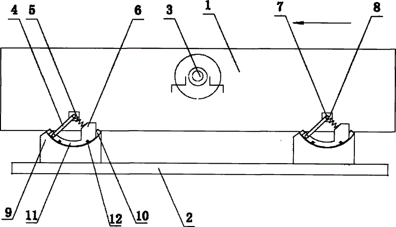
图1为本实用新型的一种结构示意图;Fig. 1 is a kind of structural representation of the utility model;
图2为本实用新型的运动轨迹示意图。Fig. 2 is a schematic diagram of the motion trajectory of the utility model.
图中:1-振动箱体,2-底座,3-激振轴,4-变轨杆,5-弹簧,6-弹簧座,7-支撑轴,8-支撑座,9-基座,10-弧形导槽,11-弧形滑板,12-锁紧螺栓。In the figure: 1-vibration box, 2-base, 3-exciting shaft, 4-rail change rod, 5-spring, 6-spring seat, 7-support shaft, 8-support seat, 9-base, 10 -arc guide groove, 11-arc slide plate, 12-lock bolt.
具体实施方式 Detailed ways
下面结合具体的实施例和附图对本实用新型作进一步的说明。Below in conjunction with specific embodiment and accompanying drawing, the utility model is further described.
实施例:如图1所示,一种单轴直线运动轨迹激振装置,包括振动箱体1、底座2和激振轴3,激振轴3设置在振动箱体1上,振动箱体1和底座2之间的四角上分别设置有四平行布置的变轨机构。Embodiment: As shown in Fig. 1, a kind of uniaxial linear motion track vibration device comprises a
每一变轨机构的结构如下:支撑轴7固定在振动箱体1上的支撑座8上。变轨杆4斜向布置在振动箱体1和底座2之间,变轨杆4的上端垂直铰接在支撑轴7上,下端铰接在弧形滑板11上,变轨杆4垂直于激振轴3的固定轴心线设置。The structure of each track changing mechanism is as follows: the
弹簧5的上端也垂直铰接在支撑轴7上,下端通过弹簧座6固定在弧形滑板11上。变轨杆4与弹簧5相垂直布置。The upper end of the
弧形导槽10设置在基座9上,弧形滑板11设置在弧形导槽10中并由锁紧螺栓12锁定。The arc-shaped
以上所述的仅是本实用新型的优选实施方式,应当指出,对于本技术领域中的普通技术人员来说,在不脱离本实用新型核心技术特征的前提下,还可以做出若干改进和修饰,这些改进和修饰也应视为本实用新型的保护范围。The above is only the preferred embodiment of the utility model, and it should be pointed out that for those of ordinary skill in the art, some improvements and modifications can be made without departing from the core technical features of the utility model. , These improvements and modifications should also be regarded as the protection scope of the present utility model.
Claims (7)
Priority Applications (1)
| Application Number | Priority Date | Filing Date | Title |
|---|---|---|---|
| CN2012200206975U CN202398514U (en) | 2012-01-04 | 2012-01-04 | Excitation device with single-axis linear motion track |
Applications Claiming Priority (1)
| Application Number | Priority Date | Filing Date | Title |
|---|---|---|---|
| CN2012200206975U CN202398514U (en) | 2012-01-04 | 2012-01-04 | Excitation device with single-axis linear motion track |
Publications (1)
| Publication Number | Publication Date |
|---|---|
| CN202398514U true CN202398514U (en) | 2012-08-29 |
Family
ID=46696192
Family Applications (1)
| Application Number | Title | Priority Date | Filing Date |
|---|---|---|---|
| CN2012200206975U Expired - Fee Related CN202398514U (en) | 2012-01-04 | 2012-01-04 | Excitation device with single-axis linear motion track |
Country Status (1)
| Country | Link |
|---|---|
| CN (1) | CN202398514U (en) |
Cited By (1)
| Publication number | Priority date | Publication date | Assignee | Title |
|---|---|---|---|---|
| CN102580910A (en) * | 2012-01-04 | 2012-07-18 | 浙江黑白矿山机械有限公司 | Single-shaft vibration exciter with linear motion trail |
-
2012
- 2012-01-04 CN CN2012200206975U patent/CN202398514U/en not_active Expired - Fee Related
Cited By (2)
| Publication number | Priority date | Publication date | Assignee | Title |
|---|---|---|---|---|
| CN102580910A (en) * | 2012-01-04 | 2012-07-18 | 浙江黑白矿山机械有限公司 | Single-shaft vibration exciter with linear motion trail |
| CN102580910B (en) * | 2012-01-04 | 2016-08-03 | 浙江黑白矿山机械有限公司 | A kind of single-shaft vibration exciter with linear motion trail |
Similar Documents
| Publication | Publication Date | Title |
|---|---|---|
| US9433977B2 (en) | Single-shaft track-changeable vibration exciter | |
| CN107185823B (en) | A dual-machine-driven sub-resonant self-synchronized vibration relaxation screen | |
| CN111468398B (en) | Novel efficient linear vibrating screen device | |
| CN202238595U (en) | Single-shaft horizontal track-changeable vibration exciter | |
| CN201261010Y (en) | Dual-spindle circular vibration exciter | |
| CN101389426B (en) | Oscillating table | |
| CN203448267U (en) | Vibration generating device | |
| CN204182578U (en) | Automatic eccentric adjustment vibrator | |
| CN100525934C (en) | Amplitude descending screening method and vibrating screen | |
| CN102247944A (en) | Single-shaft horizontally-arranged variable-track vibration exciter | |
| CN203140751U (en) | Novel double-mass conveying type vibrating shakeout machine | |
| CN101934270A (en) | Vibrating screen | |
| CN102513286B (en) | Uniaxial elliptic motion trail vibration exciter | |
| CN201823699U (en) | Line oscillating screen with single exciting motor | |
| CN105499127B (en) | Three shaft vibrations sieve with buffer storage hopper | |
| AU2012276117B2 (en) | Single-shaft track-changeable vibration exciter | |
| CN202845143U (en) | Crushing and screening machine | |
| CN202096971U (en) | Double-cavity double-movable jaw vibration jaw crusher | |
| CN202398515U (en) | Single-shaft vibration exciter with linear motion trail | |
| CN102580910B (en) | A kind of single-shaft vibration exciter with linear motion trail | |
| CN202845144U (en) | Energy-saving single-unit crushing production line | |
| CN202398516U (en) | Single-shaft vibration exciter with elliptic motion track | |
| CN101147965A (en) | Crystallizer vibrating system | |
| CN102580909A (en) | Single-axis linear movement trace vibration exciter | |
| CN203227599U (en) | Vibrating screen |
Legal Events
| Date | Code | Title | Description |
|---|---|---|---|
| C14 | Grant of patent or utility model | ||
| GR01 | Patent grant | ||
| CP03 | Change of name, title or address | ||
| CP03 | Change of name, title or address |
Address after: 321083 Shaojia Village, Yangbu Town, Wucheng District, Jinhua City, Zhejiang Province Patentee after: Zhejiang Shengda Machine Co., Ltd. Address before: 32 2006 Shaojia Village, Yangbu Town, Jinhua City, Zhejiang Province Patentee before: Zhejiang B & W Mining Machinery Co.,Ltd. |
|
| CF01 | Termination of patent right due to non-payment of annual fee | ||
| CF01 | Termination of patent right due to non-payment of annual fee |
Granted publication date: 20120829 Termination date: 20210104 |