CN202388096U - Rack for numerical control flame cutting machine - Google Patents
Rack for numerical control flame cutting machine Download PDFInfo
- Publication number
- CN202388096U CN202388096U CN2011205278123U CN201120527812U CN202388096U CN 202388096 U CN202388096 U CN 202388096U CN 2011205278123 U CN2011205278123 U CN 2011205278123U CN 201120527812 U CN201120527812 U CN 201120527812U CN 202388096 U CN202388096 U CN 202388096U
- Authority
- CN
- China
- Prior art keywords
- welded
- cutting machine
- flame cutting
- herringbone
- carriage
- Prior art date
- Legal status (The legal status is an assumption and is not a legal conclusion. Google has not performed a legal analysis and makes no representation as to the accuracy of the status listed.)
- Expired - Fee Related
Links
- 239000000758 substrate Substances 0.000 claims abstract description 8
- 230000002787 reinforcement Effects 0.000 claims description 3
- 238000005728 strengthening Methods 0.000 abstract 2
Images
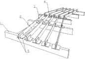
Landscapes
- Machine Tool Units (AREA)
Abstract
Description
Claims (2)
Priority Applications (1)
| Application Number | Priority Date | Filing Date | Title |
|---|---|---|---|
| CN2011205278123U CN202388096U (en) | 2011-12-16 | 2011-12-16 | Rack for numerical control flame cutting machine |
Applications Claiming Priority (1)
| Application Number | Priority Date | Filing Date | Title |
|---|---|---|---|
| CN2011205278123U CN202388096U (en) | 2011-12-16 | 2011-12-16 | Rack for numerical control flame cutting machine |
Publications (1)
| Publication Number | Publication Date |
|---|---|
| CN202388096U true CN202388096U (en) | 2012-08-22 |
Family
ID=46663048
Family Applications (1)
| Application Number | Title | Priority Date | Filing Date |
|---|---|---|---|
| CN2011205278123U Expired - Fee Related CN202388096U (en) | 2011-12-16 | 2011-12-16 | Rack for numerical control flame cutting machine |
Country Status (1)
| Country | Link |
|---|---|
| CN (1) | CN202388096U (en) |
Cited By (2)
| Publication number | Priority date | Publication date | Assignee | Title |
|---|---|---|---|---|
| CN102861967A (en) * | 2012-10-09 | 2013-01-09 | 无锡信德隆工业炉有限公司 | Module type working platform of copying cutting machine |
| CN102974899A (en) * | 2012-11-30 | 2013-03-20 | 齐重数控装备股份有限公司 | Machining method for machining positioning racks in pairs to guarantee consistency of tooth surface |
-
2011
- 2011-12-16 CN CN2011205278123U patent/CN202388096U/en not_active Expired - Fee Related
Cited By (3)
| Publication number | Priority date | Publication date | Assignee | Title |
|---|---|---|---|---|
| CN102861967A (en) * | 2012-10-09 | 2013-01-09 | 无锡信德隆工业炉有限公司 | Module type working platform of copying cutting machine |
| CN102974899A (en) * | 2012-11-30 | 2013-03-20 | 齐重数控装备股份有限公司 | Machining method for machining positioning racks in pairs to guarantee consistency of tooth surface |
| CN102974899B (en) * | 2012-11-30 | 2015-03-25 | 齐重数控装备股份有限公司 | Machining method for machining positioning racks in pairs to guarantee equal height of tooth surface |
Similar Documents
| Publication | Publication Date | Title |
|---|---|---|
| CN202509622U (en) | Steel structure supporting beam | |
| CN203247703U (en) | Steel structural plant frame | |
| CN203448908U (en) | Welding table for welding of auxiliary dumper frame | |
| CN201952959U (en) | Cornice node mechanism for steel structure | |
| CN202064492U (en) | Brace fixing mechanism used for steel structure | |
| CN202271550U (en) | Upper beam reinforcing mechanism for crane beam | |
| CN202079533U (en) | Crane assembling poppet | |
| CN202390928U (en) | Grid structure | |
| CN103482462A (en) | Spool lifting tool device | |
| CN202000827U (en) | Window upper port joint mechanism for steel structure | |
| CN202227473U (en) | Joist double-end fixing mechanism for steel structures | |
| CN203286213U (en) | Pumping unit supporting frame | |
| CN201723160U (en) | Mast of rotary drilling rig | |
| CN202247550U (en) | Hinge type gap bridge rail | |
| CN202414924U (en) | Elevator underbeam and bracket structure | |
| CN202021441U (en) | Assembly mould for steel frame vertical gusset | |
| CN202831396U (en) | Box column side extension mechanism | |
| CN201943185U (en) | Tie-beam mechanism for steel structure | |
| CN202359656U (en) | Wedge plate extension mechanism for steel structure | |
| CN202227471U (en) | Double-support mechanism for steel structure | |
| CN103615108B (en) | The bracing means of template in a kind of steel plate shear wall structure system | |
| CN202827112U (en) | Support frame assembly of vice water tank | |
| CN203304516U (en) | Novel machine frame base of die casting machine | |
| CN202031173U (en) | Sway brace strengthening mechanism for steel structure | |
| CN204606825U (en) | A kind of fast assembling-disassembling shelf structure |
Legal Events
| Date | Code | Title | Description |
|---|---|---|---|
| C14 | Grant of patent or utility model | ||
| GR01 | Patent grant | ||
| C56 | Change in the name or address of the patentee |
Owner name: ZHIFANG TECHNOLOGY CO., LTD. Free format text: FORMER NAME: ZHEJIANG JIANGXIN STEEL TRUSS CO., LTD. |
|
| CP01 | Change in the name or title of a patent holder |
Address after: Jiaxing City, Zhejiang province 314500 Tongxiang city Tongxiang Puyuan Knitting Industrial Park (Tongxiang Puyuan knitting industrial park development and construction company in the 101-112 room) Patentee after: ZHIFANG TECHNOLOGY CO., LTD. Address before: Jiaxing City, Zhejiang province 314500 Tongxiang city Tongxiang Puyuan Knitting Industrial Park (Tongxiang Puyuan knitting industrial park development and construction company in the 101-112 room) Patentee before: ZHEJIANG JIANGXIN STEEL GRID TRUSS CO., LTD |
|
| CF01 | Termination of patent right due to non-payment of annual fee | ||
| CF01 | Termination of patent right due to non-payment of annual fee |
Granted publication date: 20120822 Termination date: 20171216 |