CN202326408U - Efficient centrifugal ventilator blade structure - Google Patents
Efficient centrifugal ventilator blade structure Download PDFInfo
- Publication number
- CN202326408U CN202326408U CN2011204824695U CN201120482469U CN202326408U CN 202326408 U CN202326408 U CN 202326408U CN 2011204824695 U CN2011204824695 U CN 2011204824695U CN 201120482469 U CN201120482469 U CN 201120482469U CN 202326408 U CN202326408 U CN 202326408U
- Authority
- CN
- China
- Prior art keywords
- blades
- wheel
- blade
- wheel hub
- cone
- Prior art date
- Legal status (The legal status is an assumption and is not a legal conclusion. Google has not performed a legal analysis and makes no representation as to the accuracy of the status listed.)
- Expired - Lifetime
Links
Images


Landscapes
- Structures Of Non-Positive Displacement Pumps (AREA)
Abstract
Description
技术领域 technical field
本实用新型涉及一种高效的离心通风机叶片结构,属于风机技术领域。 The utility model relates to a high-efficiency centrifugal fan blade structure, which belongs to the technical field of fans.
背景技术 Background technique
叶轮是通风机的核心部件,它的结构、几何形状、尺寸、叶片数目和制造精度对通风机的性能有很大影响。叶片是叶轮中的主要部件,是关系到风机性能的重中之重。风机性能主要参数有流量、压力、效率、功率等。叶片的结构是风机获得高效率的至关重要的因素。背景技术的离心通风机叶片结构不合理,效率不理想,加工制造难度大,成本高。 The impeller is the core component of the fan, and its structure, geometry, size, number of blades and manufacturing precision have a great influence on the performance of the fan. The blade is the main part of the impeller, and it is the most important thing related to the performance of the fan. The main parameters of fan performance are flow, pressure, efficiency, power, etc. The structure of the blade is a crucial factor for the high efficiency of the fan. The blade structure of the centrifugal fan in the background art is unreasonable, the efficiency is not ideal, the processing and manufacturing is difficult, and the cost is high.
实用新型内容 Utility model content
本实用新型的目的是提供一种高效的离心通风机叶片结构,提高效率,加工制造容易,成本低,解决背景技术存在的上述问题。 The purpose of the utility model is to provide a high-efficiency centrifugal fan blade structure, which improves efficiency, is easy to process and manufacture, and has low cost, so as to solve the above-mentioned problems in the background technology.
本实用新型的技术方案是: The technical scheme of the utility model is:
一种高效的离心通风机叶片结构,包含叶片、轮盘、轮毂加强锥、轮毂,轮毂设置在轮盘中心,轮毂外设有轮毂加强锥,若干个叶片设置在轮盘和轮毂加强锥上,所说的叶片截面为圆弧与直线连接的单板式结构,前部为圆弧型线,后部为直线型线,为后向叶片。 A high-efficiency centrifugal fan blade structure, including blades, discs, hub reinforcement cones, and hubs. The hub is arranged in the center of the hub, and the hub is provided with hub reinforcement cones outside the hub. Several blades are arranged on the hub and hub reinforcement cones. Said blade cross-section is a single-plate structure connected by arc and straight line, the front part is arc-shaped line, and the rear part is straight-line-shaped line, which is the backward blade.
轮盘为锯齿型外缘结构,设有轮盖,轮盖为弧锥型轮盖,叶片为整体冲压成型的叶片,叶片的上部与弧锥型轮盖相接,下部与轮毂加强锥和轮盘相联接。 The wheel disc has a saw-tooth outer edge structure and is equipped with a wheel cover. The wheel cover is an arc-cone wheel cover. The blade is an integrally stamped blade. Disk connected.
本实用新型的积极效果是:叶片通过圆弧部分与直线部分的尺寸上的适当组合,使叶片进口安装角和出口安装角都达到较为合理的数值,再配合弧锥型轮盖和带有轮毂加强锥(整流)及锯齿型外缘的轮盘,使叶道内的气流在风机工作的区间内产生的损失较少,使风机获得了较高的效率,并且高效区较为宽广;本实用新型具有叶片形式简单、加工制造容易、生产成本低等特点。 The positive effect of the utility model is that the blades can reach reasonable values for the inlet and outlet installation angles of the blades through the appropriate combination of the size of the arc part and the straight part, and then cooperate with the arc-cone wheel cover and the wheel cover with the hub The reinforced cone (rectification) and the sawtooth-shaped outer edge of the wheel make the airflow in the blade channel less loss in the working range of the fan, so that the fan can obtain higher efficiency, and the high-efficiency area is relatively wide; the utility model has the advantages of The blade has the characteristics of simple form, easy processing and manufacturing, and low production cost.
附图说明 Description of drawings
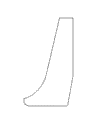
图1是本实用新型的叶片的展开图; Fig. 1 is the expanded view of blade of the present utility model;
图2是本实用新型的叶片结构的俯视图; Fig. 2 is the plan view of blade structure of the present utility model;
图3是本实用新型实施例主视图; Fig. 3 is the front view of the utility model embodiment;
图4是本实用新型实施例侧视图; Fig. 4 is a side view of the utility model embodiment;
图5是本实用新型实施例的旋转剖视图; Fig. 5 is a rotary sectional view of the utility model embodiment;
图中:叶片1、轮盘2、轮毂加强锥3、轮毂4、轮盖5。
In the figure:
具体实施方式 Detailed ways
下面结合附图,通过实施例对本实用新型做进一步说明。 Below in conjunction with accompanying drawing, the utility model is described further by embodiment.
一种高效的离心通风机叶片结构,包含叶片1、轮盘2、轮毂加强锥3、轮毂4,轮毂设置在轮盘中心,轮毂外设有轮毂加强锥,若干个叶片设置在轮盘和轮毂加强锥上,所说的叶片截面为圆弧与直线连接的单板式结构,前部为圆弧型线,后部为直线型线,为后向叶片。轮盘为锯齿型外缘结构,设有轮盖5,叶片的上部与弧锥型轮盖相接,下部与轮毂加强锥和轮盘相联接。
A high-efficiency centrifugal fan blade structure, including
在轮毂加强锥上焊接叶片的圆弧型线部分,叶片的直线型线部分焊接在轮盘上。叶片整体冲压成型。叶片上部与弧锥型轮盖焊接。 The circular arc line part of the blade is welded on the hub reinforcement cone, and the straight line part of the blade is welded on the wheel disc. The whole blade is stamped and formed. The upper part of the blade is welded with the arc cone wheel cover.
Claims (2)
Priority Applications (1)
| Application Number | Priority Date | Filing Date | Title |
|---|---|---|---|
| CN2011204824695U CN202326408U (en) | 2011-11-29 | 2011-11-29 | Efficient centrifugal ventilator blade structure |
Applications Claiming Priority (1)
| Application Number | Priority Date | Filing Date | Title |
|---|---|---|---|
| CN2011204824695U CN202326408U (en) | 2011-11-29 | 2011-11-29 | Efficient centrifugal ventilator blade structure |
Publications (1)
| Publication Number | Publication Date |
|---|---|
| CN202326408U true CN202326408U (en) | 2012-07-11 |
Family
ID=46438389
Family Applications (1)
| Application Number | Title | Priority Date | Filing Date |
|---|---|---|---|
| CN2011204824695U Expired - Lifetime CN202326408U (en) | 2011-11-29 | 2011-11-29 | Efficient centrifugal ventilator blade structure |
Country Status (1)
| Country | Link |
|---|---|
| CN (1) | CN202326408U (en) |
Cited By (6)
| Publication number | Priority date | Publication date | Assignee | Title |
|---|---|---|---|---|
| CN102943774A (en) * | 2012-08-06 | 2013-02-27 | 王书勤 | Design method of composite airfoil fan blade |
| CN103062111A (en) * | 2012-10-09 | 2013-04-24 | 宁波风机有限公司 | Fan impeller |
| CN103115021A (en) * | 2013-02-01 | 2013-05-22 | 华中科技大学 | Vane wheel device |
| CN104500426A (en) * | 2014-12-31 | 2015-04-08 | 东莞市锐天机电科技有限公司 | Energy-saving high-speed blower |
| CN104653499A (en) * | 2015-02-10 | 2015-05-27 | 南通大通宝富风机有限公司 | Fan for containment atmospheric monitoring system |
| CN108397423A (en) * | 2018-03-31 | 2018-08-14 | 合肥合博机电有限公司 | A kind of air-cooled structure on water pump |
-
2011
- 2011-11-29 CN CN2011204824695U patent/CN202326408U/en not_active Expired - Lifetime
Cited By (7)
| Publication number | Priority date | Publication date | Assignee | Title |
|---|---|---|---|---|
| CN102943774A (en) * | 2012-08-06 | 2013-02-27 | 王书勤 | Design method of composite airfoil fan blade |
| CN103062111A (en) * | 2012-10-09 | 2013-04-24 | 宁波风机有限公司 | Fan impeller |
| CN103115021A (en) * | 2013-02-01 | 2013-05-22 | 华中科技大学 | Vane wheel device |
| CN104500426A (en) * | 2014-12-31 | 2015-04-08 | 东莞市锐天机电科技有限公司 | Energy-saving high-speed blower |
| CN104653499A (en) * | 2015-02-10 | 2015-05-27 | 南通大通宝富风机有限公司 | Fan for containment atmospheric monitoring system |
| CN104653499B (en) * | 2015-02-10 | 2017-09-22 | 南通大通宝富风机有限公司 | A kind of containment atmospheric monitoring system blower fan |
| CN108397423A (en) * | 2018-03-31 | 2018-08-14 | 合肥合博机电有限公司 | A kind of air-cooled structure on water pump |
Similar Documents
| Publication | Publication Date | Title |
|---|---|---|
| CN201610861U (en) | Impeller of centrifugal fan | |
| CN102374194B (en) | Axial flow wind wheel | |
| CN102141051B (en) | Centrifugal fan impeller for range hood | |
| CN204175641U (en) | The wind wheel of air-conditioning and air-conditioning | |
| CN108869394A (en) | Axial-flow windwheel and air conditioner | |
| CN203500110U (en) | High-efficiency backward centrifugal vane wheel | |
| CN102536900A (en) | Axial flow wind wheel | |
| CN205677862U (en) | A kind of centrifugal fan for three-phase brushless alternating-current generator | |
| CN203584898U (en) | Low-noise high-efficiency central air conditioner outdoor machine cooling axial-flow fan | |
| CN103629156B (en) | A kind of central air conditioner outdoor unit but axial-flow blower of low-noise high-efficiency | |
| CN205173055U (en) | Low noise that trailing edge is buckled does not have spiral case fan wheel | |
| CN102758793B (en) | Fan blade and axial flow fan with fan blade of air conditioner | |
| CN206419268U (en) | One kind energy-conservation hypsokinesis wind wheel | |
| CN201763675U (en) | Coil pipe air blower impeller | |
| CN201934380U (en) | fan blade | |
| CN202914378U (en) | Centrifugal fan impeller for air cooling refrigerators | |
| CN202117979U (en) | Centrifugal impeller | |
| CN201448255U (en) | Backward high-pressure anti-explosion centrifugal ventilator | |
| CN204828037U (en) | Leafy centrifugal impeller | |
| CN202381392U (en) | Fixed impeller with improved air quantity and motor thereof | |
| CN204126966U (en) | A New High Efficiency Axial Flow Fan | |
| CN101936308A (en) | a fan blade | |
| CN203867970U (en) | Wind wheel | |
| CN201209591Y (en) | An impeller of an assembled air compressor in an air separation unit | |
| CN205064367U (en) | Air purifier centrifugal wind wheel |
Legal Events
| Date | Code | Title | Description |
|---|---|---|---|
| C14 | Grant of patent or utility model | ||
| GR01 | Patent grant | ||
| CX01 | Expiry of patent term |
Granted publication date: 20120711 |
|
| CX01 | Expiry of patent term |