CN202325188U - Gauze element pressing strip section - Google Patents
Gauze element pressing strip section Download PDFInfo
- Publication number
- CN202325188U CN202325188U CN2011204867417U CN201120486741U CN202325188U CN 202325188 U CN202325188 U CN 202325188U CN 2011204867417 U CN2011204867417 U CN 2011204867417U CN 201120486741 U CN201120486741 U CN 201120486741U CN 202325188 U CN202325188 U CN 202325188U
- Authority
- CN
- China
- Prior art keywords
- press strip
- gauze
- strip section
- pressing strip
- section bar
- Prior art date
- Legal status (The legal status is an assumption and is not a legal conclusion. Google has not performed a legal analysis and makes no representation as to the accuracy of the status listed.)
- Expired - Fee Related
Links
- 230000009286 beneficial effect Effects 0.000 description 1
- 238000009434 installation Methods 0.000 description 1
Images


Landscapes
- Building Environments (AREA)
Abstract
The utility model relates to a gauze element pressing strip section. The gauze element pressing strip section comprises a pressing strip body and a clamping structure arranged on the lower surface of the pressing strip body, wherein the clamping structure comprises two projected clamping strips and/or recessed clamping grooves, and the two clamping strips and/or clamping grooves are parallel to each other. According to the gauze element pressing strip section, the two clamping strips or clamping grooves are arranged, and the gauze element pressing strip section is matched with a corresponding gauze fan frame section, so that the clamping force of a gauze element can be increased, therefore, the gauze element is not easy to drop.
Description
Technical field
The utility model relates to the technical field of window sectional material, particularly relates to a kind of gauze press strip section bar.
Background technology
In the existing section bar combination window; Have only a holding tank on the overwhelming majority gauze fan, be embedded into the installation that realizes gauze in this holding tank through a press strip, the mounting structure of this gauze is fairly simple; Chucking power is limited; As long as pushing hard gauze a little just can extract out from clamp structure, cause gauze to come off, do not have gauze and answer role.
The utility model content
The purpose of the utility model is in order to address the above problem, a kind of gauze press strip section bar to be provided.
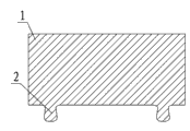
The technical scheme of the utility model is: a kind of gauze press strip section bar, comprise press strip body and the chucking structure that is arranged on press strip body soffit, and described chucking structure is the card article of two convexities, two card articles are parallel to each other.
A kind of gauze press strip section bar comprises press strip body and the chucking structure that is arranged on press strip body soffit, and described chucking structure is the draw-in groove of two depressions, and two draw-in grooves are parallel to each other.
A kind of gauze press strip section bar comprises press strip body and the chucking structure that is arranged on press strip body soffit, and described chucking structure comprises the card article of a convexity and the draw-in groove of a depression, and card article and draw-in groove are parallel to each other.
The beneficial effect of the utility model
This gauze press strip section bar is provided with two card articles or draw-in groove, after corresponding gauze fan frame section cooperates, can improve the chucking power of gauze, makes the gauze difficult drop-off.
Description of drawings
Fig. 1 is one of cross section structure sketch map of this gauze press strip section bar;
Fig. 2 be this gauze press strip section bar the cross section structure sketch map two;
Fig. 3 be this gauze press strip section bar the cross section structure sketch map three;
1. press strip bodies among the figure, 2. card article, 3. draw-in groove.
The specific embodiment
Embodiment one: referring to Fig. 1, a kind of gauze press strip section bar among the figure comprises press strip body and the chucking structure that is arranged on press strip body soffit, and described chucking structure is the card article of two convexities, and two card articles are parallel to each other.
Embodiment two: referring to Fig. 2, a kind of gauze press strip section bar among the figure comprises press strip body and the chucking structure that is arranged on press strip body soffit, and described chucking structure is the draw-in groove of two depressions, and two draw-in grooves are parallel to each other.
Embodiment three: referring to Fig. 3, a kind of gauze press strip section bar among the figure comprises press strip body and the chucking structure that is arranged on press strip body soffit, and described chucking structure comprises the card article of a convexity and the draw-in groove of a depression, and card article and draw-in groove are parallel to each other.
Claims (3)
1. gauze press strip section bar is characterized in that: this press strip section bar comprises press strip body and the chucking structure that is arranged on press strip body soffit, and described chucking structure is the card article of two convexities, and two card articles are parallel to each other.
2. gauze press strip section bar is characterized in that: this press strip section bar comprises press strip body and the chucking structure that is arranged on press strip body soffit, and described chucking structure is the draw-in groove of two depressions, and two draw-in grooves are parallel to each other.
3. gauze press strip section bar is characterized in that: this press strip section bar comprises press strip body and the chucking structure that is arranged on press strip body soffit, and described chucking structure comprises the card article of a convexity and the draw-in groove of a depression, and card article and draw-in groove are parallel to each other.
Priority Applications (1)
| Application Number | Priority Date | Filing Date | Title |
|---|---|---|---|
| CN2011204867417U CN202325188U (en) | 2011-11-30 | 2011-11-30 | Gauze element pressing strip section |
Applications Claiming Priority (1)
| Application Number | Priority Date | Filing Date | Title |
|---|---|---|---|
| CN2011204867417U CN202325188U (en) | 2011-11-30 | 2011-11-30 | Gauze element pressing strip section |
Publications (1)
| Publication Number | Publication Date |
|---|---|
| CN202325188U true CN202325188U (en) | 2012-07-11 |
Family
ID=46437170
Family Applications (1)
| Application Number | Title | Priority Date | Filing Date |
|---|---|---|---|
| CN2011204867417U Expired - Fee Related CN202325188U (en) | 2011-11-30 | 2011-11-30 | Gauze element pressing strip section |
Country Status (1)
| Country | Link |
|---|---|
| CN (1) | CN202325188U (en) |
-
2011
- 2011-11-30 CN CN2011204867417U patent/CN202325188U/en not_active Expired - Fee Related
Similar Documents
| Publication | Publication Date | Title |
|---|---|---|
| CN202380918U (en) | Structure for fixing gauze by pressing bar and gauze fan sectional material | |
| CN202325189U (en) | Window gauze sash structural section | |
| CN201714755U (en) | Clamp | |
| CN202130191U (en) | Chalk holder for drawing line in teaching | |
| CN202325014U (en) | Gauze fan section of window | |
| CN202325134U (en) | Pressing strip section bar for window gauze | |
| CN202325067U (en) | Structure for fixing gauze through pressing strip and gauze fan section bar | |
| CN203269153U (en) | Scrap electrochemical aluminum rolling-up device for stamping machine | |
| CN202820544U (en) | Photo frame with multiple frames | |
| CN202363063U (en) | Adsorption type paper clip for notice board | |
| CN202698704U (en) | Water cup clamp | |
| CN201979886U (en) | Magnet pen | |
| CN203210903U (en) | Improved paper clip | |
| CN202573527U (en) | Eraser clean-keeping sleeve | |
| CN202731098U (en) | Plate used for parking sheds | |
| CN202325187U (en) | Structure for fixing gauze net by using pressing bar and mullion section | |
| CN201687813U (en) | Fluorescent clamp | |
| CN201792576U (en) | Clip | |
| CN203584140U (en) | Pressing plate sectional material | |
| CN203305710U (en) | Writing pen for clamping fragile objects | |
| CN201685636U (en) | Anti-rolling pencil clamp | |
| CN202685593U (en) | Novel book end | |
| CN202986410U (en) | Anti-myopia frame | |
| CN201970593U (en) | Dual-purpose seal for unit and date | |
| CN202391222U (en) | Automobile door handle |
Legal Events
| Date | Code | Title | Description |
|---|---|---|---|
| C14 | Grant of patent or utility model | ||
| GR01 | Patent grant | ||
| CF01 | Termination of patent right due to non-payment of annual fee |
Granted publication date: 20120711 Termination date: 20141130 |
|
| EXPY | Termination of patent right or utility model |