CN202325187U - Structure for fixing gauze net by using pressing bar and mullion section - Google Patents
Structure for fixing gauze net by using pressing bar and mullion section Download PDFInfo
- Publication number
- CN202325187U CN202325187U CN2011204813012U CN201120481301U CN202325187U CN 202325187 U CN202325187 U CN 202325187U CN 2011204813012 U CN2011204813012 U CN 2011204813012U CN 201120481301 U CN201120481301 U CN 201120481301U CN 202325187 U CN202325187 U CN 202325187U
- Authority
- CN
- China
- Prior art keywords
- gauze
- gauze net
- press strip
- mullion
- right angle
- Prior art date
- Legal status (The legal status is an assumption and is not a legal conclusion. Google has not performed a legal analysis and makes no representation as to the accuracy of the status listed.)
- Expired - Fee Related
Links
- 230000008878 coupling Effects 0.000 claims description 3
- 238000010168 coupling process Methods 0.000 claims description 3
- 238000005859 coupling reaction Methods 0.000 claims description 3
- 230000009286 beneficial effect Effects 0.000 description 1
- 238000005516 engineering process Methods 0.000 description 1
- 239000011521 glass Substances 0.000 description 1
- 238000009434 installation Methods 0.000 description 1
- 239000000463 material Substances 0.000 description 1
- 238000012216 screening Methods 0.000 description 1
Images

Landscapes
- Clamps And Clips (AREA)
Abstract
The utility model discloses a structure for fixing a gauze net by using a pressing bar and a mullion section. The structure comprises a pressing bar, a mullion and a gauze net, wherein the section of the mullion is of a T shape; the mullion comprises an outdoor surface and back ribs which are vertically connected to the inner side of the outdoor surface; two sides of the back ribs are two symmetrical right-angled stepped surfaces; clamping grooves are formed on two right-angled surfaces of each right-angled stepped surface; the cross section of the pressing bar is approximately shaped like a rectangle; two adjacent side faces of the pressing bar are gauze net pressing surfaces; an angle part where the two gauze net pressing surfaces are connected is a gauze net pressing angle; protruding clamping bars are arranged on the two gauze net pressing surfaces; the two clamping bars are matched with two clamping grooves on the right-angled stepped surfaces of the mullion; and the gauze net is positioned between the stepped surfaces of the mullion and the gauze net pressing surfaces of the pressing bar and is clamped by the two pairs of clamping bars and clamping grooves. In the structure for fixing the gauze net by using the pressing bar and the mullion section, two clamping grooves and two clamping bars are arranged, the gauze net can be firmly arranged on a window, and the gauze net hardly falls off.
Description
Technical field
The utility model relates to the technical field of window sectional material, particularly relate to a kind of press strip with in the fixing structure of gauze of section bar very.
Background technology
In the existing section bar combination window, some single fan is fixed, and the structure that exists on this window is endured both sides in being exactly; One fan is that what to install is glass, and another fan is the window screening of installing, and very goes up in this type window of market sale now and generally has only a holding tank; Be embedded into the installation that realizes gauze in this holding tank through a rubber strip; The mounting structure of this gauze is fairly simple, and chucking power is limited, just can from clamp structure, extract out as long as push hard gauze a little; Cause gauze to come off, do not have gauze and answer role.
The utility model content
The purpose of the utility model is in order to address the above problem, provide a kind of press strip with in the fixing structure of gauze of section bar very.
The technical scheme of the utility model is: a kind of press strip with in the fixing structure of gauze of section bar very; Comprise press strip, in very, gauze; Enduring cross sectional shape in described is T shape; Comprise outdoor be vertically connected on outdoor inboard backing strip, described backing strip both sides are the right angle platform terrace of two symmetries, are equipped with draw-in groove on two right angle faces of each right angle platform terrace; The cross section of described press strip is approximate rectangle; Two adjacent sides of press strip are the gauze pressure surface; The bight that two gauze pressure surfaces connect is that gauze is pressed the angle, is equipped with protruding card article on two above-mentioned gauze pressure surfaces, described two card articles with in the coupling of two draw-in grooves on the right angle platform terrace endured; Described gauze between the gauze pressure surface of the step surface endured and press strip, and by two pairs of card articles and draw-in groove clamping.
In very the draw-in groove of step surface be positioned at the outer end of right angle face; The angle is pressed away from gauze in the position of card article on the described press strip on the gauze pressure surface.
The beneficial effect of the utility model
This press strip with in very section bar fixedly the structure of gauze be provided with two draw-in grooves and card article, can be with firm being installed on the window of gauze, gauze can not come off easily.
Description of drawings
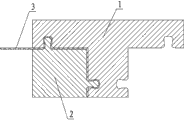
Fig. 1 be this press strip with in the fixing cross section structure sketch map of the structure of gauze of section bar very;
Fig. 2 is the cross section structure sketch map of its press strip.
Among the figure in 1. very, 2. press strip, 3. gauze,
Wherein 2-1. gauze pressure surface, 2-2. gauze are pressed angle, 2-3. card article.
The specific embodiment
Embodiment one: referring to Fig. 1; Among the figure a kind of press strip with in the fixing structure of gauze of section bar very; Comprise press strip, in very, gauze, described in very cross sectional shape be T shape, comprise outdoor be vertically connected on outdoor inboard backing strip; Described backing strip both sides are the right angle platform terrace of two symmetries, are equipped with draw-in groove on two right angle faces of each right angle platform terrace; The cross section of described press strip is approximate rectangle; Two adjacent sides of press strip are the gauze pressure surface; The bight that two gauze pressure surfaces connect is that gauze is pressed the angle, is equipped with protruding card article on two above-mentioned gauze pressure surfaces, described two card articles with in the coupling of two draw-in grooves on the right angle platform terrace endured; Described gauze between the gauze pressure surface of the step surface endured and press strip, and by two pairs of card articles and draw-in groove clamping.In very the draw-in groove of step surface be positioned at the outer end of right angle face; The angle is pressed away from gauze in the position of card article on the described press strip on the gauze pressure surface.
Claims (2)
- A press strip with in the fixing structure of gauze of section bar very; Comprise press strip, in very, gauze; It is characterized in that: enduring cross sectional shape in described is T shape; Comprise outdoor be vertically connected on outdoor inboard backing strip, described backing strip both sides are the right angle platform terrace of two symmetries, are equipped with draw-in groove on two right angle faces of each right angle platform terrace; The cross section of described press strip is approximate rectangle; Two adjacent sides of press strip are the gauze pressure surface; The bight that two gauze pressure surfaces connect is that gauze is pressed the angle, is equipped with protruding card article on two above-mentioned gauze pressure surfaces, described two card articles with in the coupling of two draw-in grooves on the right angle platform terrace endured; Described gauze between the gauze pressure surface of the step surface endured and press strip, and by two pairs of card articles and draw-in groove clamping.
- 2. press strip according to claim 1 with in the fixing structure of gauze of section bar very, it is characterized in that: in endure step surface draw-in groove be positioned at the outer end of right angle face; The angle is pressed away from gauze in the position of card article on the described press strip on the gauze pressure surface.
Priority Applications (1)
| Application Number | Priority Date | Filing Date | Title |
|---|---|---|---|
| CN2011204813012U CN202325187U (en) | 2011-11-28 | 2011-11-28 | Structure for fixing gauze net by using pressing bar and mullion section |
Applications Claiming Priority (1)
| Application Number | Priority Date | Filing Date | Title |
|---|---|---|---|
| CN2011204813012U CN202325187U (en) | 2011-11-28 | 2011-11-28 | Structure for fixing gauze net by using pressing bar and mullion section |
Publications (1)
| Publication Number | Publication Date |
|---|---|
| CN202325187U true CN202325187U (en) | 2012-07-11 |
Family
ID=46437169
Family Applications (1)
| Application Number | Title | Priority Date | Filing Date |
|---|---|---|---|
| CN2011204813012U Expired - Fee Related CN202325187U (en) | 2011-11-28 | 2011-11-28 | Structure for fixing gauze net by using pressing bar and mullion section |
Country Status (1)
| Country | Link |
|---|---|
| CN (1) | CN202325187U (en) |
-
2011
- 2011-11-28 CN CN2011204813012U patent/CN202325187U/en not_active Expired - Fee Related
Similar Documents
| Publication | Publication Date | Title |
|---|---|---|
| WO2010140878A3 (en) | A method of mounting a multitude of devices for harnessing solar energy | |
| CN202519837U (en) | Detachable connection structure for stone curtain wall | |
| CN202325134U (en) | Pressing strip section bar for window gauze | |
| CN202325067U (en) | Structure for fixing gauze through pressing strip and gauze fan section bar | |
| CN102266168A (en) | Furniture edge sealing strip | |
| CN202324995U (en) | Window large-frame section bar | |
| CN202325014U (en) | Gauze fan section of window | |
| CN202325186U (en) | Structure for fixing gauze by compressive strip and big-frame section bar | |
| CN102509929B (en) | Contact pin connector assembly | |
| CN203153068U (en) | Efficient intelligent automatic reverse pressing clamping device | |
| CN202747683U (en) | Refrigeration parts special for cooling fan | |
| CN202380918U (en) | Structure for fixing gauze by pressing bar and gauze fan sectional material | |
| CN204950297U (en) | Connection structure of sheet and basement | |
| CN202325188U (en) | Gauze element pressing strip section | |
| CN203348897U (en) | Edge sealing section material frame | |
| CN204541402U (en) | A kind of edge sealing structure for intelligentized Furniture | |
| CN201857752U (en) | Template for pouring floor concrete | |
| CN201718801U (en) | Furniture edge banding | |
| CN202325189U (en) | Window gauze sash structural section | |
| CN203361438U (en) | L-shaped ceiling notch trimming device | |
| CN202812701U (en) | Platy body fixing seat | |
| CN204386360U (en) | A kind of plug-in type inclined-plane fixed structure section bar | |
| CN201542195U (en) | Screen fastener fixing device | |
| CN202139825U (en) | Edge banding strip of wood-plastic floor | |
| CN203397646U (en) | Aluminum profile frame with arched slideway for advertising board |
Legal Events
| Date | Code | Title | Description |
|---|---|---|---|
| C14 | Grant of patent or utility model | ||
| GR01 | Patent grant | ||
| CF01 | Termination of patent right due to non-payment of annual fee |
Granted publication date: 20120711 Termination date: 20141128 |
|
| EXPY | Termination of patent right or utility model |