CN202309174U - Mobile wireless charging dock - Google Patents
Mobile wireless charging dock Download PDFInfo
- Publication number
- CN202309174U CN202309174U CN2011204539840U CN201120453984U CN202309174U CN 202309174 U CN202309174 U CN 202309174U CN 2011204539840 U CN2011204539840 U CN 2011204539840U CN 201120453984 U CN201120453984 U CN 201120453984U CN 202309174 U CN202309174 U CN 202309174U
- Authority
- CN
- China
- Prior art keywords
- electric core
- circuit board
- mobile wireless
- loam cake
- lower cover
- Prior art date
- Legal status (The legal status is an assumption and is not a legal conclusion. Google has not performed a legal analysis and makes no representation as to the accuracy of the status listed.)
- Expired - Fee Related
Links
Images


Abstract
The utility model discloses a mobile wireless charging dock, which comprises a shell, a transmitting coil, a circuit board and a cell, wherein the transmitting coil, the circuit board and the cell are electrically connected with one another; the circuit board and the cell are arranged in the shell; the shell comprises an upper cover and a lower cover, which are connected in a clamping way; the upper cover is provided with a bottom plate; and the energy of the cell is converted into magnetic energy through the transmitting coil. According to the mobile wireless charging dock, the energy of the cell is converted into the magnetic energy through the transmitting coil to charge a battery of a mobile phone or digital equipment, so that a wireless charging function is realized.
Description
Technical field
The utility model relates to a kind of charging device, especially relates to a kind of mobile wireless cradle.
Background technology
Along with the communication technology, particularly developing rapidly of mobile communication technology worldwide has increasing people and brings into use various portable electronic commodity (like mobile phone and personal digital assistant etc.).The portable electronic commodity with its be easy to carry, advantage such as easy to use liked by people.Existing portable electronic commodity can obtain power supply through following dual mode; A kind of mode is used AC power for utilizing the external life of charging adapter that is complementary with the portable electronic commodity; Another kind of mode is at the suitable internal battery of the internal preset of portable electronic commodity, no matter uses the power supply of above-mentioned any mode all can make these portable electronic commodity reach the purpose of operate as normal.Then; Existing charging adapter is to be connected in life with between AC power and the portable electronic commodity with wired mode; But more wired because of the length of the connecting line of charging adapter, usually can make troubles, and carrying of charging adapter can comparatively bother to the user.
In addition; The portable electronic commodity generally need adopt specific, corresponding charging adapter, and the user just need carry charging adapter, otherwise; Exhaust because of electric weight and can't in time find under the situation of corresponding charging adapter rechargeable battery occurring, bring great inconvenience for work and life; Simultaneously, existing charging adapter adopts life to use ac power supply, and under the environment of not living with AC power, charging adapter just can't use.
Summary of the invention
The utility model is to the defective that the above-mentioned background technology exists a kind of mobile wireless cradle that charges with way of electromagnetic induction to be provided.
For realizing above-mentioned purpose, the utility model discloses a kind of mobile wireless cradle, comprise housing, transmitting coil, circuit board and electric core; Electrically connect each other between said transmitting coil, circuit board and the electric core; Said circuit board and electric core place in the said housing, and said housing comprises loam cake and lower cover, and said loam cake holds with said lower cover and is connected; Said loam cake is provided with base plate, and said electric core energy is converted into magnetic energy through said transmitting coil.
Further, offer some perforation on the said base plate, said circuit board is electrically connected with the LED display lamp, and said LED display lamp coupling is arranged in the said perforation, and said LED display lamp is indicated said electric core state of charge.
Further, said base plate end protrudes out downwards and is provided with side plate, offers power hole on the said side plate, and said circuit board is electrically connected with power input interface, and said power input interface is fastened in the said power hole.
Further, said base plate end protrudes out downwards and is provided with side plate, offers switch hole on the said side plate, and said circuit board is electrically connected with dc switch, and said dc switch is fastened in the said switch hole.
Further, said lower cover is concaved with bearing groove.
The utility model discloses a kind of mobile wireless cradle; Comprise housing, transmitting coil, circuit board and electric core, electrically connect each other between said transmitting coil, circuit board and the electric core that said circuit board and electric core place in the said housing; Said housing comprises loam cake and lower cover; Said loam cake holds with said lower cover and is connected, and said loam cake is provided with base plate, and said electric core energy is converted into magnetic energy through said transmitting coil; Said lower cover is concaved with storage tank, and said electric core is installed in the said storage tank.
Further, said storage tank two ends are provided with shell fragment, and said shell fragment and said circuit board electrically connect, and said electric core is made up of some dry cells, corresponding with the said shell fragment respectively connection of said dry cell.
The utility model discloses a kind of mobile wireless cradle; Comprise housing, transmitting coil, circuit board and electric core; Electrically connect each other between said transmitting coil, circuit board and the electric core, said circuit board and electric core place in the said housing, and said housing comprises loam cake, lower cover and folded sheet; Said loam cake and lower cover hold with folded sheet respectively and are connected; Said electric core energy is converted into magnetic energy through said transmitting coil, and said folded sheet is provided with solar panel, and said solar panel and said electric core electrically connect.
Further; Said solar panel comprises first solar panels and second solar panels; Said folded sheet is provided with first folding part and second folding part, and said first solar panels are arranged at said first folding part one side, and said second solar panels are arranged at said second folding part one side; Said loam cake is fastened in the said first folding part opposite side, and said lower cover is fastened in the said second folding part opposite side.
Further, cover on said and offer perforation, said circuit board is connected with the LED display lamp, and said LED display lamp coupling is arranged in the said perforation, and said LED display lamp is indicated said electric core state of charge.
In sum, the utility model mobile wireless cradle is magnetic energy through transmitting coil is set with electric core Conversion of energy, and then gives mobile phone or digital equipment battery charge; Simultaneously, the user is not having under the situation of external power source, utilizes transmitting coil to give mobile phone or digital equipment battery with the dry cell power conversion for magnetic energy, reaches the wireless charging function.
Description of drawings
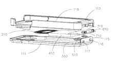
Fig. 1 is the structural representation of the utility model first embodiment.
Fig. 2 is the exploded view at another visual angle of the utility model shown in Figure 1.
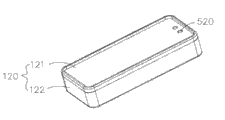
Fig. 3 is the structural representation of the utility model second embodiment.
Fig. 4 is the exploded view at another visual angle of the utility model shown in Figure 3.
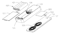
Fig. 5 is the structural representation of the utility model the 3rd embodiment.
Fig. 6 is the exploded view of the utility model shown in Figure 5.
Embodiment
For further understanding characteristic, technological means and the specific purposes that reached, the function of the utility model, the utility model is described in further detail below in conjunction with accompanying drawing and embodiment.
First embodiment:
See also Fig. 1 and Fig. 2; The utility model mobile wireless cradle comprises housing 110, transmitting coil 210, circuit board 310 and electric core 410; Electrically connect each other between said transmitting coil 210, circuit board 310 and the electric core 410, said housing 110 comprises loam cake 111 and lower cover 112, and said loam cake 111 holds with said lower cover 112 and is connected; Said loam cake 111 is provided with base plate 113; Offer some perforation 114 on the said base plate 113, said base plate 113 ends protrude out downwards and are provided with side plate 115, offer switch hole 116 and power hole 117 on the said side plate 115.Said transmitting coil 210, circuit board 310 and electric core 410 place in the space that said loam cake 111 and lower cover 112 enclose, and said lower cover 112 is concaved with bearing groove 118, with coupling mobile phone or digital equipment is installed.
Said electric core 410 energy storages; Said circuit board 310 is electrically connected with LED display lamp 510, dc switch 610 and power input interface 710; Said LED display lamp 510 couplings are arranged in the said perforation 114; Said dc switch 610 is fastened in the said switch hole 116, and said power input interface 710 is fastened in the said power hole 117, and 510 pairs of said electric core 410 state of charge of said LED display lamp are indicated; Said dc switch 610 is controlled the connecting and disconnecting of the circuit that said electric core 410 energy is flowed into said transmitting coil 210, and said power input interface 710 connects external power supplys so that said electric core 410 is charged.
The user can connect charging wire with power input interface 710 when giving mobile phone or digital equipment battery charge, the external power supply energy is converted into magnetic energy through said transmitting coil 210; In the time mobile phone or digital equipment battery charge need not being given, can realize the disconnection of charging circuit through breaking off dc switch 610.Simultaneously; When said electric core 410 electric weight of said LED display lamp 510 promptings are not enough, can connect charging wire through power input interface 710; Said electric core 410 is carried out energy storage, and when not having external power supply, the utility model is magnetic energy output through said transmitting coil with electric core Conversion of energy.
Second embodiment:
See also Fig. 3 and Fig. 4; The utility model mobile wireless cradle comprises housing 120, transmitting coil 220, circuit board 320 and electric core 420; Electrically connect each other between said transmitting coil 120, circuit board 320 and the electric core 420, said housing 120 comprises loam cake 121 and lower cover 122, and said loam cake 121 holds with said lower cover 122 and is connected; Said loam cake 121 is provided with base plate 123, offers some perforation 124 on the said base plate 123.Said transmitting coil 220 and circuit board 320 place in the space that said loam cake 121 and lower cover 122 enclose; Said lower cover 122 is concaved with storage tank 125; Said storage tank 125 two ends are provided with shell fragment 126; Said shell fragment 126 electrically connects with said circuit board 320, and said lower cover 122 is provided with battery cover 127, in order to seal said storage tank 125.
Said electric core 420 is made up of some dry cells 421, and said dry cell 421 is installed in the said storage tank 125, said dry cell 421 respectively with said shell fragment 126 corresponding connections.Be connected with LED display lamp 520 on the said circuit board 320,520 pairs of said dry cell 421 state of charge of said LED display lamp are indicated.
The user is not having under the situation of external power source, said dry cell 421 placed in the said storage tank 125, and be that magnetic energy is given mobile phone or digital equipment battery through said transmitting coil 220 with said dry cell 421 power conversion.
The 3rd embodiment:
See also Fig. 5 and Fig. 6; The utility model mobile wireless cradle comprises housing 130, transmitting coil 230, circuit board 330 and electric core 430; Electrically connect each other between said transmitting coil 230, circuit board 330 and the electric core 430, said housing 130 comprises loam cake 131, lower cover 132 and folded sheet 133, and said folded sheet is provided with solar panel 139; Said solar panel 139 electrically connects with said electric core 430; Said solar panel 139 comprises first solar panels 136 and second solar panels 137, and said folded sheet 133 is provided with first folding part 134 and second folding part 135, and said first solar panels 136 are arranged at said first folding part 134 1 sides; Said second solar panels 137 are arranged at said second folding part 135 1 sides; Said loam cake 131 is fastened in said first folding part 134 opposite sides, and said lower cover 132 is fastened in said second folding part 135 opposite sides, offers perforation 138 on the said loam cake 131.
Said first folding part 134 holds with said loam cake 131 and is connected; Said second folding part 135 holds with said lower cover 132 and is connected; Said transmitting coil 230 and circuit board 330 place in the space that said first folding part 134 and said loam cake 131 enclose; In the space that said electric core 430 encloses as for said second folding part 135 and said lower cover 132; Said circuit board 330 is connected with LED display lamp 530, and said LED display lamp 530 couplings are arranged in the said perforation 138, and 530 pairs of said electric core 430 state of charge of said LED display lamp are indicated.
The user is when giving mobile phone or digital equipment battery charge; Can said folded sheet 133 be launched; Said first solar panels 136 and second solar panels 137 absorb solar energy and change and give said electric core 430, through said transmitting coil 230 said electric core 430 storage power are converted into magnetic energy.Simultaneously, 133 pairs of said electric cores 430 of deployable said folded sheet carry out energy storage when said electric core 430 electric weight of said LED display lamp 530 promptings are not enough; In the time of need not using the utility model like the user, can doubling be carried out in first folding part 134 and second folding part 135 of said folded sheet 133, reduce the usage space area, be convenient to place.
In sum, the utility model mobile wireless cradle is magnetic energy through transmitting coil is set with electric core Conversion of energy, and then gives mobile phone or digital equipment battery charge; Simultaneously, the user is not having under the situation of external power source, utilizes transmitting coil to give mobile phone or digital equipment battery with the dry cell power conversion for magnetic energy, reaches the wireless charging function.
The above embodiment has only expressed a kind of execution mode of the utility model, and it describes comparatively concrete and detailed, but can not therefore be interpreted as the restriction to the utility model scope.Should be pointed out that for the person of ordinary skill of the art under the prerequisite that does not break away from the utility model design, can also make some distortion and improvement, these all belong to the protection range of the utility model.Therefore, the protection range of the utility model should be as the criterion with accompanying claims.
Claims (10)
1. mobile wireless cradle; Comprise housing (110), circuit board (310) and electric core (410); Electrically connect each other between said circuit board (310) and the electric core (410); Said circuit board (310) and electric core (410) place in the said housing (110); Said housing (110) comprises loam cake (111) and lower cover (112), and said loam cake (111) holds with said lower cover (112) and is connected, and said loam cake (111) is provided with base plate (113); It is characterized in that: also comprise the transmitting coil (210) that electrically connects with said circuit board (310) and electric core (410), said electric core (410) energy is converted into magnetic energy through said transmitting coil (210).
2. mobile wireless cradle according to claim 1; It is characterized in that: offer some perforation (114) on the said base plate (113); Said circuit board (310) is electrically connected with LED display lamp (510); Said LED display lamp (510) coupling is arranged in the said perforation (114), and said LED display lamp (510) is indicated said electric core (410) state of charge.
3. mobile wireless cradle according to claim 1; It is characterized in that: said base plate (113) end protrudes out downwards and is provided with side plate (115); Offer power hole (117) on the said side plate (115); Said circuit board (310) is electrically connected with power input interface (710), and said power input interface (710) is fastened in the said power hole (117).
4. mobile wireless cradle according to claim 1; It is characterized in that: said base plate (113) end protrudes out downwards and is provided with side plate (115); Offer switch hole (116) on the said side plate (115); Said circuit board (310) is electrically connected with dc switch (610), and said dc switch (610) is fastened in the said switch hole (116).
5. mobile wireless cradle according to claim 1 is characterized in that: said lower cover (112) is concaved with bearing groove (118).
6. mobile wireless cradle; Comprise housing (120), circuit board (320) and electric core (420); Electrically connect each other between said circuit board (320) and the electric core (420), said circuit board (320) and electric core (420) place in the said housing (120), and said housing (120) comprises loam cake (121) and lower cover (122); Said loam cake (121) holds with said lower cover (122) and is connected; Said loam cake (121) is provided with base plate (123), it is characterized in that: also comprise the transmitting coil (220) that electrically connects with said circuit board (320) and electric core (420), said electric core (420) energy is converted into magnetic energy through said transmitting coil (220); Said lower cover (122) is concaved with storage tank (125), and said electric core (420) is installed in the said storage tank (125).
7. mobile wireless cradle according to claim 6; It is characterized in that: said storage tank (125) two ends are provided with shell fragment (126); Said shell fragment (126) electrically connects with said circuit board (320); Said electric core (420) is made up of some dry cells (421), said dry cell (421) respectively with the corresponding connection of said shell fragment (126).
8. mobile wireless cradle; Comprise housing (130), circuit board (330) and electric core (430); Electrically connect each other between said circuit board (330) and the electric core (430); Said circuit board (330) and electric core (430) place in the said housing (130); Said housing (130) comprises loam cake (131), lower cover (132) and folded sheet (133); Said loam cake (131) and lower cover (132) hold with folded sheet (133) respectively and be connected, and it is characterized in that: also comprise the transmitting coil (230) that electrically connects with said circuit board (330) and electric core (430), said electric core (430) energy is converted into magnetic energy through said transmitting coil (230); Said folded sheet (133) is provided with solar panel (139), and said solar panel (139) electrically connects with said electric core (430).
9. mobile wireless cradle according to claim 8; It is characterized in that: said solar panel (139) comprises first solar panels (136) and second solar panels (137); Said folded sheet (133) is provided with first folding part (134) and second folding part (135); Said first solar panels (136) are arranged at said first folding part (134) one sides; Said second solar panels (137) are arranged at said second folding part (135) one sides, and said loam cake (131) is fastened in said first folding part (134) opposite side, and said lower cover (132) is fastened in said second folding part (135) opposite side.
10. mobile wireless cradle according to claim 8; It is characterized in that: offer perforation (138) on the said loam cake (131); Said circuit board (330) is connected with LED display lamp (530); Said LED display lamp (530) coupling is arranged in the said perforation (138), and said LED display lamp (530) is indicated said electric core (430) state of charge.
Priority Applications (1)
| Application Number | Priority Date | Filing Date | Title |
|---|---|---|---|
| CN2011204539840U CN202309174U (en) | 2011-11-16 | 2011-11-16 | Mobile wireless charging dock |
Applications Claiming Priority (1)
| Application Number | Priority Date | Filing Date | Title |
|---|---|---|---|
| CN2011204539840U CN202309174U (en) | 2011-11-16 | 2011-11-16 | Mobile wireless charging dock |
Publications (1)
| Publication Number | Publication Date |
|---|---|
| CN202309174U true CN202309174U (en) | 2012-07-04 |
Family
ID=46377987
Family Applications (1)
| Application Number | Title | Priority Date | Filing Date |
|---|---|---|---|
| CN2011204539840U Expired - Fee Related CN202309174U (en) | 2011-11-16 | 2011-11-16 | Mobile wireless charging dock |
Country Status (1)
| Country | Link |
|---|---|
| CN (1) | CN202309174U (en) |
Cited By (4)
| Publication number | Priority date | Publication date | Assignee | Title |
|---|---|---|---|---|
| CN103280859A (en) * | 2013-05-31 | 2013-09-04 | 王洪军 | Solar wireless charging device |
| CN105024487A (en) * | 2014-04-21 | 2015-11-04 | 郑雅轩 | Hand-operated power generation type power supply |
| CN108123507A (en) * | 2016-11-29 | 2018-06-05 | 佑骅科技(深圳)有限公司 | A kind of portable wireless power transfering device |
| CN116505622A (en) * | 2023-06-26 | 2023-07-28 | 深圳市优品文创科技有限公司 | Detachable 3C digital equipment power module |
-
2011
- 2011-11-16 CN CN2011204539840U patent/CN202309174U/en not_active Expired - Fee Related
Cited By (6)
| Publication number | Priority date | Publication date | Assignee | Title |
|---|---|---|---|---|
| CN103280859A (en) * | 2013-05-31 | 2013-09-04 | 王洪军 | Solar wireless charging device |
| CN103280859B (en) * | 2013-05-31 | 2015-08-19 | 王洪军 | Solar energy radio charging device |
| CN105024487A (en) * | 2014-04-21 | 2015-11-04 | 郑雅轩 | Hand-operated power generation type power supply |
| CN108123507A (en) * | 2016-11-29 | 2018-06-05 | 佑骅科技(深圳)有限公司 | A kind of portable wireless power transfering device |
| CN116505622A (en) * | 2023-06-26 | 2023-07-28 | 深圳市优品文创科技有限公司 | Detachable 3C digital equipment power module |
| CN116505622B (en) * | 2023-06-26 | 2023-08-25 | 深圳市优品文创科技有限公司 | Detachable 3C digital equipment power module |
Similar Documents
| Publication | Publication Date | Title |
|---|---|---|
| CN202524124U (en) | Portable power source | |
| CN105071515A (en) | Mobile power pack having wireless emission receiving function | |
| CN202309174U (en) | Mobile wireless charging dock | |
| CN101322296A (en) | Accumulation energy type mobile charging adapter | |
| CN201515253U (en) | Portable solar power supply device | |
| CN203039388U (en) | Separating bidirectional wireless charging stand | |
| CN201577049U (en) | Overturn type multifunctional solar portable power supply | |
| CN202524114U (en) | Mobile power supply capable of wireless charging | |
| CN201541137U (en) | Solar wireless charging device | |
| CN204130115U (en) | A kind of sun power station poster with Wi-Fi and mobile phone charging function | |
| CN203456896U (en) | Folding cover type wireless charging mobile power pack | |
| CN102157969B (en) | Portable charge device | |
| US20140167690A1 (en) | Wireless charging battery module and charging structure of the same | |
| CN106162081A (en) | A kind of rural power grids meter copying device | |
| CN102684320B (en) | A kind of wireless power supply | |
| CN201797005U (en) | Back clamped type external battery for iPhones | |
| CN204230951U (en) | Back of the body lid structure | |
| CN210669611U (en) | Ultra-thin solar charging is precious | |
| CN202586422U (en) | Portable power source capable of being used for wireless charging | |
| CN204030677U (en) | With the portable power source of solar energy and wireless charging | |
| CN202564710U (en) | Multifunctional mobile power socket board | |
| CN201450351U (en) | Portable solar energy charger | |
| CN201893580U (en) | Portable solar cell phone charger | |
| CN205141746U (en) | Multifunctional mobile phone uses wireless charger | |
| EP3503347A1 (en) | Detachable solar charging device |
Legal Events
| Date | Code | Title | Description |
|---|---|---|---|
| C14 | Grant of patent or utility model | ||
| GR01 | Patent grant | ||
| C53 | Correction of patent for invention or patent application | ||
| CB03 | Change of inventor or designer information |
Inventor after: Duan Xingdai Inventor after: Li Song Inventor before: Duan Xingwei Inventor before: Li Song |
|
| COR | Change of bibliographic data |
Free format text: CORRECT: INVENTOR; FROM: DUAN XINGWEI LI SONG TO: DUAN XINGYI LI SONG |
|
| C17 | Cessation of patent right | ||
| CF01 | Termination of patent right due to non-payment of annual fee |
Granted publication date: 20120704 Termination date: 20121116 |