CN202264110U - Automatic collecting device - Google Patents
Automatic collecting device Download PDFInfo
- Publication number
- CN202264110U CN202264110U CN2011202611904U CN201120261190U CN202264110U CN 202264110 U CN202264110 U CN 202264110U CN 2011202611904 U CN2011202611904 U CN 2011202611904U CN 201120261190 U CN201120261190 U CN 201120261190U CN 202264110 U CN202264110 U CN 202264110U
- Authority
- CN
- China
- Prior art keywords
- material receiving
- rewinding
- receiving device
- workpiece
- automatic material
- Prior art date
- Legal status (The legal status is an assumption and is not a legal conclusion. Google has not performed a legal analysis and makes no representation as to the accuracy of the status listed.)
- Expired - Lifetime
Links
- 239000000463 material Substances 0.000 claims description 27
- 230000003139 buffering effect Effects 0.000 abstract description 3
- 238000000034 method Methods 0.000 description 6
- 238000013461 design Methods 0.000 description 1
- 238000005516 engineering process Methods 0.000 description 1
- 238000003754 machining Methods 0.000 description 1
- 239000002184 metal Substances 0.000 description 1
- 238000012544 monitoring process Methods 0.000 description 1
- 238000012856 packing Methods 0.000 description 1
- 238000012545 processing Methods 0.000 description 1
Images
Landscapes
- Specific Conveyance Elements (AREA)
Abstract
The utility model discloses an automatic collecting device, which comprises a working table. The automatic collecting device is characterized in that a hollow collecting container and an ejector rod are vertically arranged on the working table, openings are arranged at two ends of the hollow collecting container, and the ejector rod can move up and down in the collecting container. The automatic collecting device consists of the ejector rod which is controlled by a programmable controller and arranged on the lower side of the collecting container, when a workpiece enters the automatic collecting device, the ejector rod can descend by the distance equal to the thickness of the workpiece, accordingly, a sufficient buffering effect can be realized, and the workpiece is prevented from being impacted. In addition, the automatic collecting device has the advantages of simple structure, high automation degree and the like.
Description
Technical field
The utility model belongs to field of machining, is specifically related to a kind of automatic material receiving device.
Background technology
Automatically processing device often all be unable to do without the material collecting device of automation.The material collecting device basic functions is continuously the workpiece of coming from process equipment to be collected.The process of collecting workpiece generally need provide enough bufferings, avoids the workpiece of damaging, and the circular metal works of vertical collection particularly is during like gear.How can much more as far as possible and avoid workpiece to collect workpiece automatically as far as possible, be present urgent problem with damaging.
The utility model content
The utility model provides a kind of solution of the above problems, provides a kind of automaticity high automatic material receiving device.
The technical scheme of the utility model provides a kind of automatic material receiving device, and it comprises workbench, it is characterized in that: the rewinding container and the ejector beam that can in said rewinding container, move up and down that vertically are provided with the hollow of both ends open on the said workbench.
Preferably, said ejector beam is driven by stepper motor or cylinder.
Preferably; Also be provided with circular rotatable material receiving desk on the said workbench; Evenly be provided with several said rewinding containers near its outer circumferential edges place on the said material receiving desk; Said material receiving desk and said rewinding container lower ending opening junction are provided with the circular push-rod hole that connects, and said ejector beam passes said push-rod hole, get in the rewinding container center hole.
Preferably, said rewinding container is several said push-rod hole columns on every side that are vertically set on.
Preferably, the said rewinding container tubular rewinding tube that is both ends open.
Preferably, said workbench is provided with position sensor.
Preferably, said stepper motor, cylinder and position sensor are controlled by Programmable Logic Controller PLC.
The automatic material receiving device of the utility model comprises the ejector beam through Controlled by Programmable Controller rewinding container below, and workpiece of every entering just reduces a thickness of workpiece downwards, therefore enough bufferings can be provided, and avoids workpiece to damage.The utlity model has simple in structure, automaticity advantages of higher.
Description of drawings
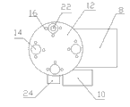
Fig. 1 is the vertical view of a kind of automatic material receiving device of the utility model;
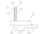
Fig. 2 is the left view of a kind of automatic material receiving device of the utility model.
The specific embodiment
The specific embodiment in the face of the utility model is described in further detail down.
As depicted in figs. 1 and 2; A kind of automatic material receiving device of the utility model; Comprise workbench 8, workbench 8 is provided with the circular rotatable material receiving desk 12 that is driven by stepper motor 10, evenly is provided with four circular push-rod holes 14 that connect near material receiving desk 12 outer circumferential edges.Be with the rewinding container 15 of the hollow of vertical both ends open on each push-rod hole 14; Rewinding container 15 can be the cylinder of both ends open, also can be the space of passing through the accommodated workpiece that 3 columns 16 that are vertically set on around the blanking port surround shown in the utility model first embodiment.Process equipment (not shown) is sent into rewinding container with the workpiece that processes 18 through the upper opening 20 of rewinding container 15 through modes such as cylinders.Whether upper opening 20 places of rewinding container 15 are provided with position sensor (not shown) monitoring has workpiece 18 to get into, and information is sent into Programmable Logic Controller PLC (not shown).Ejector beam 22 is upward through push-rod hole 14, gets in the rewinding container also can under the driving of stepper motor 24 (or cylinder), move up and down therein.
A kind of automatic material receiving device of the utility model in use; After workpiece 18 is admitted to rewinding container 15; Programmable Logic Controller PLC receives the signal of sensor; Drive ejector beam 22 by stepper motor 24 (or cylinder) then and move down a thickness of workpiece, wait for next workpiece, upper surface and the process equipment that rigidly connects the workpiece of receipts this moment send surperficial concordant that workpiece comes.So the circulation workpiece of packing into is filled workpiece to this rewinding container.Drive ejector beam 22 and be moved down into material receiving desk 12 belows; Can drive angle of material receiving desk 12 rotations by stepper motor then; Make another rewinding container 15 move to this position; Last ejector beam 22 is upward through push-rod hole 14 and stretches in this rewinding container 15, and rises to its upper surface and process equipment and send surperficial concordant that workpiece comes, continuation wait rewinding.So back and forth, just can carry out the rewinding operation continuously.
Above embodiment is merely the utility model a kind of embodiment wherein, and it describes comparatively concrete and detailed, but can not therefore be interpreted as the restriction to the utility model claim.Should be pointed out that for the person of ordinary skill of the art under the prerequisite that does not break away from the utility model design, can also make some distortion and improvement, these all belong to the protection domain of the utility model.Therefore, the protection domain of the utility model patent should be as the criterion with accompanying claims.
Claims (6)
1. automatic material receiving device, it comprises workbench, it is characterized in that: the rewinding container and the ejector beam that can in said rewinding container, move up and down that vertically are provided with the hollow of both ends open on the said workbench.
2. a kind of automatic material receiving device according to claim 1 is characterized in that: said ejector beam is driven by stepper motor or cylinder.
3. a kind of automatic material receiving device according to claim 1; It is characterized in that: also be provided with circular rotatable material receiving desk on the said workbench; Evenly be provided with several said rewinding containers near its outer circumferential edges place on the said material receiving desk; Said material receiving desk and said rewinding container lower ending opening junction are provided with the circular push-rod hole that connects, and said ejector beam passes said push-rod hole, get in the rewinding container center hole.
4. a kind of automatic material receiving device according to claim 3 is characterized in that: said rewinding container is several said push-rod hole columns on every side that are vertically set on.
5. a kind of automatic material receiving device according to claim 1 is characterized in that: the tubular rewinding tube that said rewinding container is a both ends open.
6. a kind of automatic material receiving device according to claim 1, it is characterized in that: said workbench is provided with position sensor.
Priority Applications (1)
| Application Number | Priority Date | Filing Date | Title |
|---|---|---|---|
| CN2011202611904U CN202264110U (en) | 2011-07-22 | 2011-07-22 | Automatic collecting device |
Applications Claiming Priority (1)
| Application Number | Priority Date | Filing Date | Title |
|---|---|---|---|
| CN2011202611904U CN202264110U (en) | 2011-07-22 | 2011-07-22 | Automatic collecting device |
Publications (1)
| Publication Number | Publication Date |
|---|---|
| CN202264110U true CN202264110U (en) | 2012-06-06 |
Family
ID=46154921
Family Applications (1)
| Application Number | Title | Priority Date | Filing Date |
|---|---|---|---|
| CN2011202611904U Expired - Lifetime CN202264110U (en) | 2011-07-22 | 2011-07-22 | Automatic collecting device |
Country Status (1)
| Country | Link |
|---|---|
| CN (1) | CN202264110U (en) |
Cited By (2)
| Publication number | Priority date | Publication date | Assignee | Title |
|---|---|---|---|---|
| CN102398186A (en) * | 2011-07-22 | 2012-04-04 | 大同齿轮(昆山)有限公司 | Automatic material receiving device |
| CN103474373A (en) * | 2012-06-08 | 2013-12-25 | 矽品科技(苏州)有限公司 | Electroplating machine material collecting device |
-
2011
- 2011-07-22 CN CN2011202611904U patent/CN202264110U/en not_active Expired - Lifetime
Cited By (3)
| Publication number | Priority date | Publication date | Assignee | Title |
|---|---|---|---|---|
| CN102398186A (en) * | 2011-07-22 | 2012-04-04 | 大同齿轮(昆山)有限公司 | Automatic material receiving device |
| CN103474373A (en) * | 2012-06-08 | 2013-12-25 | 矽品科技(苏州)有限公司 | Electroplating machine material collecting device |
| CN103474373B (en) * | 2012-06-08 | 2016-03-09 | 矽品科技(苏州)有限公司 | Electroplating machine material collecting device |
Similar Documents
| Publication | Publication Date | Title |
|---|---|---|
| CN201711445U (en) | Automatic material loading and unloading manipulator | |
| CN201881016U (en) | Work device of tap turntable | |
| CN202894568U (en) | Automatic rotary special net welding machine | |
| CN102745636A (en) | Facility for automatically collecting waste liquid in volumetric flasks | |
| CN206065561U (en) | A kind of full-automatic saw blade broaching machine | |
| CN201473060U (en) | Cover separating device of can making machine | |
| CN102274992B (en) | Automatic drilling machine | |
| CN208555766U (en) | NC turret punch machine waste material collection device | |
| CN102167167A (en) | Automatic encasing device for equipment | |
| CN202265199U (en) | Novel automatic feeding device of pipe cutter | |
| CN202163914U (en) | Automatic material receiving machine | |
| CN206068850U (en) | A kind of saw blade multistation blanking device | |
| CN207387054U (en) | Header sawing sheet chamfering all-in-one machine | |
| CN102398186A (en) | Automatic material receiving device | |
| CN210938090U (en) | Full-automatic production line for drilling, tapping and chamfering detection of supporting plate nut | |
| CN101804578A (en) | Chip removing device of machine tool | |
| CN203958657U (en) | A kind of female rail packing machine | |
| CN203565606U (en) | Gantry type high speed precise automatic punching machine with two centers and four circular guide posts | |
| CN204564979U (en) | Collecting device of punch press | |
| CN204449642U (en) | A kind of laser cutting machine | |
| CN203045036U (en) | Section cutting saw machine | |
| CN104044761B (en) | A kind of female rail packing machine | |
| CN202212607U (en) | Automatic drilling machine | |
| CN210755882U (en) | Heavy pipe laser cutting equipment | |
| CN203557016U (en) | Containing device |
Legal Events
| Date | Code | Title | Description |
|---|---|---|---|
| C14 | Grant of patent or utility model | ||
| GR01 | Patent grant | ||
| CX01 | Expiry of patent term | ||
| CX01 | Expiry of patent term |
Granted publication date: 20120606 |