CN202253576U - Plate type economizer for power station boiler - Google Patents
Plate type economizer for power station boiler Download PDFInfo
- Publication number
- CN202253576U CN202253576U CN2011203351548U CN201120335154U CN202253576U CN 202253576 U CN202253576 U CN 202253576U CN 2011203351548 U CN2011203351548 U CN 2011203351548U CN 201120335154 U CN201120335154 U CN 201120335154U CN 202253576 U CN202253576 U CN 202253576U
- Authority
- CN
- China
- Prior art keywords
- corrugated
- plate
- flue gas
- heat exchange
- area
- Prior art date
- Legal status (The legal status is an assumption and is not a legal conclusion. Google has not performed a legal analysis and makes no representation as to the accuracy of the status listed.)
- Expired - Fee Related
Links
- UGFAIRIUMAVXCW-UHFFFAOYSA-N Carbon monoxide Chemical compound [O+]#[C-] UGFAIRIUMAVXCW-UHFFFAOYSA-N 0.000 claims abstract description 26
- 239000003546 flue gas Substances 0.000 claims abstract description 26
- XLYOFNOQVPJJNP-UHFFFAOYSA-N water Substances O XLYOFNOQVPJJNP-UHFFFAOYSA-N 0.000 claims abstract description 19
- 239000000428 dust Substances 0.000 abstract description 5
- 229910000831 Steel Inorganic materials 0.000 abstract 1
- 238000009825 accumulation Methods 0.000 abstract 1
- 239000010959 steel Substances 0.000 abstract 1
- 238000010586 diagram Methods 0.000 description 5
- 238000004519 manufacturing process Methods 0.000 description 3
- 241001061823 Plagopterus Species 0.000 description 1
- 230000003670 easy-to-clean Effects 0.000 description 1
- 230000000694 effects Effects 0.000 description 1
- 230000008676 import Effects 0.000 description 1
- 239000000463 material Substances 0.000 description 1
- 238000000034 method Methods 0.000 description 1
- 238000011084 recovery Methods 0.000 description 1
- 239000002918 waste heat Substances 0.000 description 1
- 238000003466 welding Methods 0.000 description 1
Images


Classifications
-
- Y—GENERAL TAGGING OF NEW TECHNOLOGICAL DEVELOPMENTS; GENERAL TAGGING OF CROSS-SECTIONAL TECHNOLOGIES SPANNING OVER SEVERAL SECTIONS OF THE IPC; TECHNICAL SUBJECTS COVERED BY FORMER USPC CROSS-REFERENCE ART COLLECTIONS [XRACs] AND DIGESTS
- Y02—TECHNOLOGIES OR APPLICATIONS FOR MITIGATION OR ADAPTATION AGAINST CLIMATE CHANGE
- Y02E—REDUCTION OF GREENHOUSE GAS [GHG] EMISSIONS, RELATED TO ENERGY GENERATION, TRANSMISSION OR DISTRIBUTION
- Y02E20/00—Combustion technologies with mitigation potential
- Y02E20/30—Technologies for a more efficient combustion or heat usage
Landscapes
- Heat-Exchange Devices With Radiators And Conduit Assemblies (AREA)
Abstract
本实用新型涉及一种电站锅炉板式省煤器,包括波纹板换热芯体、烟气进出口管路和水进出口管路组成,波纹板换热芯体放置于换热器外壳内,换热器外壳的前、后两侧连接烟气进出口管路,左、右两侧连接水进出口管路,波纹板换热芯体由多块波纹板按一定方式叠放,每块波纹板由波纹区和平面区组成,波纹板一侧与相邻波纹板按照相同的结构顺序叠放,相邻两波纹板的之间间隙形成板间距相同的水流波形通道;波纹板另一侧与相邻波纹板按照波纹区的波谷相对波谷,波峰相对波峰的顺序叠放,该波谷相对波谷,波峰相对波峰的区间形成烟气流管状通道。本实用新型结构紧凑,减少了钢材用量和占地空间,提高换热效率且由于烟气在管状通道流道,烟气流阻小,不易积灰。

The utility model relates to a plate-type economizer for a power plant boiler, which consists of a corrugated plate heat exchange core body, a flue gas inlet and outlet pipeline and a water inlet and outlet pipeline. The front and rear sides of the heater shell are connected to the flue gas inlet and outlet pipelines, and the left and right sides are connected to the water inlet and outlet pipelines. The corrugated plate heat exchange core is stacked in a certain way by multiple corrugated plates. Each corrugated plate It is composed of a corrugated area and a flat area. One side of the corrugated plate and the adjacent corrugated plates are stacked in the same structural order, and the gap between two adjacent corrugated plates forms a water flow wave channel with the same plate spacing; Adjacent corrugated plates are stacked in the order that the troughs are relative to the troughs, and the crests are relative to the crests in the corrugated area. The interval between the troughs and the crests forms a pipe-like channel for flue gas flow. The utility model has a compact structure, reduces steel consumption and floor space, improves heat exchange efficiency, and because the flue gas flows in the tubular channel, the flue gas flow resistance is small, and dust accumulation is not easy.
Description
技术领域 technical field
本实用新型涉及一种电站锅炉板式省煤器,属电站锅炉余热回收节能设备技术领域。 The utility model relates to a plate-type economizer for a power station boiler, which belongs to the technical field of waste heat recovery and energy-saving equipment for power station boilers. the
背景技术 Background technique
目前电站锅炉所用的省煤器都是采用光管或翅片管式省煤器,翅片管式省煤器大多使用焊接缠绕翅片或胀管翅片,但翅片根部热阻较大,传热效果欠佳,并且紧凑度低。因此,管式省煤器换热能力差,效率低,需要消耗大量的管材,占地面积大,生产成本高,而且由于烟气与换热管是垂直接触,导致流阻增加,容易积灰并且换热管磨损加大,影响省煤器的寿命。 At present, the economizers used in power plant boilers are all light tube or finned tube economizers. Most of the finned tube economizers use welded wound fins or expanded tube fins, but the thermal resistance at the root of the fins is relatively large. Heat transfer is poor and compactness is low. Therefore, the tube-type economizer has poor heat transfer capacity and low efficiency, consumes a large amount of pipe materials, occupies a large area, and has high production costs. Moreover, due to the vertical contact between the flue gas and the heat exchange tubes, the flow resistance increases and it is easy to accumulate dust. And the wear of the heat exchange tube increases, which affects the life of the economizer. the
实用新型内容 Utility model content
本实用新型的目的是提供一种结构紧凑、换热效果好、烟气压力损失小,不容易积灰和结垢,生产成本低的一种电站锅炉板式省煤器。 The purpose of this utility model is to provide a plate type economizer for power plant boilers with compact structure, good heat exchange effect, small flue gas pressure loss, not easy to accumulate dust and scale, and low production cost. the
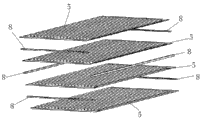
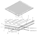
本实用新型通过以下技术方案实现的,本实用新型一种电站锅炉板式省煤器包括:包括波纹板换热芯体1、换热器外壳2、烟气进出口管路3和水进出口管路4组成,其中:波纹板换热芯体1放置于换热器外壳2内,换热器外壳2为矩形结构,其前、后、左、右四周开口,换热器外壳2的前、后两侧分别连接烟气进出口管路3,左、右两侧分别连接水进出口管路4,所述波纹板换热芯体1由多块波纹板5按一定的方式叠放而成,每块波纹板5由波纹区5.1和平面区5.2组成,波纹区5.1位于平面区5.2上方,一块波纹板5一侧与相邻波纹板5按照相同的结构顺序叠放,相邻两波纹板5的之间间隙形成板间距相同的水流波形通道7;一块波纹板5另一侧与相邻波纹板5按照波纹区5.1的波谷相对波谷,波峰相对波峰的顺序叠放,该波谷相对波谷,波峰相对波峰的区间形成烟气流管状通道6。
The utility model is realized through the following technical solutions. A utility model boiler plate economizer includes: a corrugated plate
本实用新型中,所述波纹板5的四周设有边条8。
In the present utility model,
本实用新型中,所述波纹板5为矩形板,其一侧的平面区5.2的宽度等于另一侧平面区宽度和半个波纹周期之和。
In the present utility model, the
本实用新型中,烟气流管状通道6满足椭圆曲线、圆弧、正弦曲线或六边形等,烟气流管状通道6的当量直径在10mm-30mm,两块波纹板叠放形成的通道成直通形。 In the utility model, the flue gas flow tubular channel 6 satisfies elliptic curves, circular arcs, sinusoidal curves or hexagons, etc., the equivalent diameter of the flue gas flow tubular channel 6 is 10mm-30mm, and the channel formed by stacking two corrugated plates is Straight through shape. the
本实用新型中,所述水流波形通道7的高度为1mm-20mm,两块波纹板叠放形成的通道成波浪形。 In the utility model, the height of the water flow waveform channel 7 is 1mm-20mm, and the channel formed by stacking two corrugated plates is wave-shaped. the
本实用新型的优点是:1)烟气和水在波纹板换热芯体内所有换热表面都是一次表面,换热效率大幅提高,结构紧凑,占地面积小。2)汇集了管式和板式换热器的优点,烟气流通过管状通道,压损低,不易积灰和结垢,清灰方便,波形通道水湍流程度大,不易集垢,而且波形通道可以按情况调整板间距。3)在进入管状通道之前的两块波纹板片的间隙完全可以很好的通过烟气,克服了以往进入管状流前板间距小的问题。4)生产工艺简单,成本低,并且易于组成模块,安装方便。 The advantages of the utility model are: 1) All the heat exchange surfaces of flue gas and water in the corrugated plate heat exchange core are primary surfaces, the heat exchange efficiency is greatly improved, the structure is compact, and the floor area is small. 2) Combining the advantages of tube and plate heat exchangers, the flue gas flow passes through the tubular channel, the pressure loss is low, it is not easy to accumulate dust and scale, and it is easy to clean the dust. The board spacing can be adjusted according to the situation. 3) The gap between the two corrugated plates before entering the tubular channel can completely pass the flue gas, which overcomes the previous problem of small spacing between the plates before entering the tubular flow. 4) The production process is simple, the cost is low, and it is easy to form modules and easy to install. the
附图说明 Description of drawings
图1为本实用新型结构图示。 Fig. 1 is a structural representation of the utility model. the
图2为本实用新型单组通道组装示意图。 Fig. 2 is a schematic diagram of the assembly of a single channel of the utility model. the
图3为本实用新型通道内工质流动示意图。 Fig. 3 is a schematic diagram of working medium flow in the channel of the present invention. the
图4 本实用新型波纹板换热芯体结构示意图。 Fig. 4 Schematic diagram of the structure of the corrugated plate heat exchange core of the utility model. the
图5 本实用新型波纹板示意图。 Figure 5 is a schematic diagram of the corrugated plate of the utility model. the
图6 本实用新型通道结构示意图。 Figure 6 is a schematic diagram of the channel structure of the utility model. the
图中标号:1为波纹板换热芯体,2为换热器外壳,3为烟气进出口管路,4为水进出口管路,5为波纹板,5.1为波纹区,5.2为平面区,6为烟气流管状通道,7为水流波形通道,8为边条。 Numbers in the figure: 1 is the corrugated plate heat exchange core, 2 is the heat exchanger shell, 3 is the flue gas inlet and outlet pipeline, 4 is the water inlet and outlet pipeline, 5 is the corrugated plate, 5.1 is the corrugated area, 5.2 is the plane In the zone, 6 is the flue gas flow tubular channel, 7 is the water flow wave channel, and 8 is the edge strip. the
具体实施方式 Detailed ways
下面通过附图结合实施例进一步说明本实用新型。 Further illustrate the utility model below in conjunction with embodiment by accompanying drawing. the
实施例1:参照图1,它包括波纹板换热芯体1、换热器外壳2、烟气进出口管路3、水进出口管路4。所述波纹板换热芯体1有多块波纹板5按一定的组合叠放而成形成烟气流管状通道6和水流波形通道7,通过间隔焊接波纹板上下边框边条而形成烟气进出口和水进出口。
Embodiment 1: Referring to FIG. 1 , it includes a corrugated plate
波纹板5是由波纹区5.1和平面区5.2组成,波纹板一侧的平面区宽度等于另一侧平面区宽度和半个波纹周期之和。
The
所述波纹板换热芯体是由多块波纹板片按一定的方式叠放在一起形成的,波纹板波谷相对波谷,波峰相对波峰叠放形成板间距相同的水波纹通道,而且形成一个板束,另一板束稍宽平面区与之对齐,并且波峰相对波谷形成烟气管状流道。板片之间用边条8固定。
The corrugated plate heat exchange core is formed by stacking a plurality of corrugated plates together in a certain way. The corrugated plate troughs are opposite to the troughs, and the wave crests are stacked to form water corrugated channels with the same plate spacing, and form a plate bundle, and the slightly wider plane area of the other plate bundle is aligned with it, and the crests are opposite to the troughs to form a flue gas tubular flow channel. Fix with
所述的烟气流管状通道6满足椭圆曲线、圆弧、正弦曲线、六边形等,波纹通道的当量直径在10mm-30mm,两块波纹板叠放形成的通道成直通形。 The flue gas flow tubular channel 6 satisfies elliptic curves, circular arcs, sinusoidal curves, hexagons, etc. The equivalent diameter of the corrugated channel is 10mm-30mm, and the channel formed by stacking two corrugated plates is in a straight-through shape. the
所述的水流波形通道7,高度在1mm-20mm,两块波纹板叠放形成的通道成波浪形。 The water flow wave channel 7 has a height of 1mm-20mm, and the channel formed by stacking two corrugated plates is wavy. the
Claims (5)
Priority Applications (1)
| Application Number | Priority Date | Filing Date | Title |
|---|---|---|---|
| CN2011203351548U CN202253576U (en) | 2011-09-08 | 2011-09-08 | Plate type economizer for power station boiler |
Applications Claiming Priority (1)
| Application Number | Priority Date | Filing Date | Title |
|---|---|---|---|
| CN2011203351548U CN202253576U (en) | 2011-09-08 | 2011-09-08 | Plate type economizer for power station boiler |
Publications (1)
| Publication Number | Publication Date |
|---|---|
| CN202253576U true CN202253576U (en) | 2012-05-30 |
Family
ID=46114812
Family Applications (1)
| Application Number | Title | Priority Date | Filing Date |
|---|---|---|---|
| CN2011203351548U Expired - Fee Related CN202253576U (en) | 2011-09-08 | 2011-09-08 | Plate type economizer for power station boiler |
Country Status (1)
| Country | Link |
|---|---|
| CN (1) | CN202253576U (en) |
Cited By (15)
| Publication number | Priority date | Publication date | Assignee | Title |
|---|---|---|---|---|
| CN102954459A (en) * | 2012-11-12 | 2013-03-06 | 同济大学 | Novel plate type economizer |
| CN103528420A (en) * | 2013-10-10 | 2014-01-22 | 同济大学 | Novel heat-transmission plate sheet for GGH |
| CN103759288A (en) * | 2014-01-06 | 2014-04-30 | 同济大学 | Novel plate type air preheater |
| CN104033881A (en) * | 2013-03-04 | 2014-09-10 | 同济大学 | Plate-and-shell type coal economizer |
| CN104154785A (en) * | 2014-08-01 | 2014-11-19 | 浙江银轮机械股份有限公司 | Aluminum seal strip type heat regenerator for road diesel engine waste heat utilizing ORC system |
| CN104457345A (en) * | 2013-09-17 | 2015-03-25 | 中国石油化工股份有限公司 | Fin plate heat exchanger for condensing waste heat recovery |
| CN105547014A (en) * | 2016-01-22 | 2016-05-04 | 上海银锅热能设备有限公司 | Novel heat exchanger |
| CN106123673A (en) * | 2016-07-27 | 2016-11-16 | 郴州钖涛化工有限公司 | A kind of dust-laden high-temperature flue gas heat recovery vibrating dust removing plate type heat exchanger |
| CN106322353A (en) * | 2015-07-06 | 2017-01-11 | 天津华赛尔传热设备有限公司 | Plate type low-temperature economizer |
| CN107504477A (en) * | 2016-06-14 | 2017-12-22 | 天津华赛尔传热设备有限公司 | A kind of pressure regulation heat-exchange system of low-level (stack-gas) economizer |
| CN107504476A (en) * | 2016-06-14 | 2017-12-22 | 天津华赛尔传热设备有限公司 | A kind of heat-exchange system of low-level (stack-gas) economizer |
| CN108253835A (en) * | 2016-12-28 | 2018-07-06 | 杭州三花家电热管理系统有限公司 | Plate-type heat-exchange core and with its plate heat exchanger |
| JP2018204578A (en) * | 2017-06-08 | 2018-12-27 | 株式会社デンソー | Heat exchanger |
| CN110095001A (en) * | 2019-05-13 | 2019-08-06 | 江苏双良低碳产业技术研究院有限公司 | A kind of air-cooled board-like heat exchanger of mixed type printed wire of high-pressure hydrogen storing |
| CN116146970A (en) * | 2023-04-24 | 2023-05-23 | 厦门铭光能源科技有限公司 | A welded plate economizer |
-
2011
- 2011-09-08 CN CN2011203351548U patent/CN202253576U/en not_active Expired - Fee Related
Cited By (21)
| Publication number | Priority date | Publication date | Assignee | Title |
|---|---|---|---|---|
| CN102954459B (en) * | 2012-11-12 | 2014-09-17 | 同济大学 | Novel plate type economizer |
| CN102954459A (en) * | 2012-11-12 | 2013-03-06 | 同济大学 | Novel plate type economizer |
| CN104033881B (en) * | 2013-03-04 | 2016-08-03 | 同济大学 | A kind of shell-and-plate economizer |
| CN104033881A (en) * | 2013-03-04 | 2014-09-10 | 同济大学 | Plate-and-shell type coal economizer |
| CN104457345A (en) * | 2013-09-17 | 2015-03-25 | 中国石油化工股份有限公司 | Fin plate heat exchanger for condensing waste heat recovery |
| CN103528420A (en) * | 2013-10-10 | 2014-01-22 | 同济大学 | Novel heat-transmission plate sheet for GGH |
| CN103759288A (en) * | 2014-01-06 | 2014-04-30 | 同济大学 | Novel plate type air preheater |
| CN103759288B (en) * | 2014-01-06 | 2017-01-25 | 同济大学 | Plate Air Preheater |
| CN104154785A (en) * | 2014-08-01 | 2014-11-19 | 浙江银轮机械股份有限公司 | Aluminum seal strip type heat regenerator for road diesel engine waste heat utilizing ORC system |
| CN104154785B (en) * | 2014-08-01 | 2015-11-25 | 浙江银轮机械股份有限公司 | For the aluminium sealing strip type regenerator of road diesel engine Waste Heat Reuse ORC system |
| CN106322353A (en) * | 2015-07-06 | 2017-01-11 | 天津华赛尔传热设备有限公司 | Plate type low-temperature economizer |
| CN105547014A (en) * | 2016-01-22 | 2016-05-04 | 上海银锅热能设备有限公司 | Novel heat exchanger |
| CN107504476A (en) * | 2016-06-14 | 2017-12-22 | 天津华赛尔传热设备有限公司 | A kind of heat-exchange system of low-level (stack-gas) economizer |
| CN107504477A (en) * | 2016-06-14 | 2017-12-22 | 天津华赛尔传热设备有限公司 | A kind of pressure regulation heat-exchange system of low-level (stack-gas) economizer |
| CN106123673A (en) * | 2016-07-27 | 2016-11-16 | 郴州钖涛化工有限公司 | A kind of dust-laden high-temperature flue gas heat recovery vibrating dust removing plate type heat exchanger |
| CN106123673B (en) * | 2016-07-27 | 2018-07-31 | 郴州钖涛环保科技有限公司 | A kind of dust-laden high-temperature flue gas heat recovery vibrating dust removing plate heat exchanger |
| CN108253835A (en) * | 2016-12-28 | 2018-07-06 | 杭州三花家电热管理系统有限公司 | Plate-type heat-exchange core and with its plate heat exchanger |
| CN108253835B (en) * | 2016-12-28 | 2020-04-07 | 杭州三花微通道换热器有限公司 | Plate type heat exchange core and plate type heat exchanger with same |
| JP2018204578A (en) * | 2017-06-08 | 2018-12-27 | 株式会社デンソー | Heat exchanger |
| CN110095001A (en) * | 2019-05-13 | 2019-08-06 | 江苏双良低碳产业技术研究院有限公司 | A kind of air-cooled board-like heat exchanger of mixed type printed wire of high-pressure hydrogen storing |
| CN116146970A (en) * | 2023-04-24 | 2023-05-23 | 厦门铭光能源科技有限公司 | A welded plate economizer |
Similar Documents
| Publication | Publication Date | Title |
|---|---|---|
| CN102954459B (en) | Novel plate type economizer | |
| CN202267394U (en) | Primary surface heat exchanger for flue gas waste heat recovery | |
| CN105806109B (en) | Counterflow Finned Plate Heat Exchanger for Gas-to-Gas Heat Exchange | |
| WO2018141245A1 (en) | Plate-type gas-to-gas heat exchanger | |
| CN103759288B (en) | Plate Air Preheater | |
| CN104033881B (en) | A kind of shell-and-plate economizer | |
| CN203336568U (en) | Plate-type economizer | |
| CN104677147A (en) | All-welded plate type heat exchanger for multi-stream gas-to-gas heat exchange | |
| CN101672587A (en) | Gas-phase plate type heat exchanger | |
| CN201229133Y (en) | Plate-fin heat exchanger | |
| CN202255027U (en) | A bionic honeycomb heat exchanger plate | |
| CN203586890U (en) | Plate type air-air heat exchanger | |
| CN206001436U (en) | A kind of straight passage structures low-level (stack-gas) economizer | |
| CN107023817B (en) | A straight channel structure low temperature economizer | |
| CN205718592U (en) | The corrugated board cluster of a kind of one side is contactless straight-through runner | |
| CN207300005U (en) | A kind of board-like gas-gas heat exchanger | |
| CN203115974U (en) | Plate-shell-type coal economizer | |
| CN113218218A (en) | Copper-aluminum composite material inner and outer finned tube heat exchanger | |
| CN110530179B (en) | Symmetrical bubbling type plate heat transfer element | |
| CN206787361U (en) | A kind of lozenge fin tube binding structure | |
| CN101592444A (en) | Wavefront heat plate type economizer for gas and oil fired boiler flue gas waste heat recovery | |
| CN214892760U (en) | Copper-aluminum composite material inner and outer finned tube heat exchanger | |
| CN204829863U (en) | Board -like low -level (stack -gas) economizer | |
| CN112797834B (en) | Heat exchange tube fin with corrugations | |
| CN203687726U (en) | Heat transfer pipe and gas heat exchanger using heat transfer pipe |
Legal Events
| Date | Code | Title | Description |
|---|---|---|---|
| C14 | Grant of patent or utility model | ||
| GR01 | Patent grant | ||
| CF01 | Termination of patent right due to non-payment of annual fee |
Granted publication date: 20120530 Termination date: 20140908 |
|
| EXPY | Termination of patent right or utility model |