CN202216016U - Separating type heat radiation LED lamp - Google Patents
Separating type heat radiation LED lamp Download PDFInfo
- Publication number
- CN202216016U CN202216016U CN2011203166087U CN201120316608U CN202216016U CN 202216016 U CN202216016 U CN 202216016U CN 2011203166087 U CN2011203166087 U CN 2011203166087U CN 201120316608 U CN201120316608 U CN 201120316608U CN 202216016 U CN202216016 U CN 202216016U
- Authority
- CN
- China
- Prior art keywords
- heat radiation
- chamber
- radiation chamber
- led
- power supply
- Prior art date
- Legal status (The legal status is an assumption and is not a legal conclusion. Google has not performed a legal analysis and makes no representation as to the accuracy of the status listed.)
- Expired - Lifetime
Links
- 230000005855 radiation Effects 0.000 title claims abstract description 131
- 238000001816 cooling Methods 0.000 claims description 9
- 230000037361 pathway Effects 0.000 abstract 1
- 230000000191 radiation effect Effects 0.000 abstract 1
- 230000000694 effects Effects 0.000 description 6
- 239000000463 material Substances 0.000 description 6
- 230000017525 heat dissipation Effects 0.000 description 4
- 238000000034 method Methods 0.000 description 3
- 239000004065 semiconductor Substances 0.000 description 3
- 239000004411 aluminium Substances 0.000 description 2
- 229910052782 aluminium Inorganic materials 0.000 description 2
- XAGFODPZIPBFFR-UHFFFAOYSA-N aluminium Chemical compound [Al] XAGFODPZIPBFFR-UHFFFAOYSA-N 0.000 description 2
- 238000009413 insulation Methods 0.000 description 2
- 239000007769 metal material Substances 0.000 description 2
- RYGMFSIKBFXOCR-UHFFFAOYSA-N Copper Chemical compound [Cu] RYGMFSIKBFXOCR-UHFFFAOYSA-N 0.000 description 1
- 229910045601 alloy Inorganic materials 0.000 description 1
- 239000000956 alloy Substances 0.000 description 1
- 230000009286 beneficial effect Effects 0.000 description 1
- 229910052802 copper Inorganic materials 0.000 description 1
- 239000010949 copper Substances 0.000 description 1
- 230000007812 deficiency Effects 0.000 description 1
- 238000005516 engineering process Methods 0.000 description 1
- 239000011521 glass Substances 0.000 description 1
- 238000005286 illumination Methods 0.000 description 1
- 238000004519 manufacturing process Methods 0.000 description 1
- 239000002184 metal Substances 0.000 description 1
- 229910052751 metal Inorganic materials 0.000 description 1
- 229920003023 plastic Polymers 0.000 description 1
- 239000004033 plastic Substances 0.000 description 1
- 238000005057 refrigeration Methods 0.000 description 1
- 239000000758 substrate Substances 0.000 description 1
Images




Landscapes
- Arrangement Of Elements, Cooling, Sealing, Or The Like Of Lighting Devices (AREA)
Abstract
The utility model provides a separating type heat radiation LED lamp, and relates to the field of LED lighting. The separating type heat radiation LED lamp comprises a cylindrical first heat radiation chamber and a flat-box shaped second heat radiation chamber, one end of the first heat radiation chamber is connected and communicated with the second heat radiation chamber, the second heat radiation chamber is provided with at least an air vent, thereby forming a hollow heat radiation system of the first heat radiation chamber and a pathway for circulation of air from the opening, going through the first heat radiation chamber, and going through the second heat radiation until flowing out of the air vent; the chamber wall of the first heat radiation chamber along the length direction and a heat radiation structure are combined into one body, an LED circuit board surrounds the chamber wall, an LED illuminant and a lampshade are disposed on the LED circuit board; the second heat radiation chamber is also connected and communicated with a power supply chamber for installing a power source, and the power supply chamber is also connected with a lamp holder. The separating type heat radiation LED lamp is advantageous in that, heat radiation effect is improved; the LED illuminant and the heat radiation system of the power supply are separated, mutual heat interference is prevented, and electrical performances are improved in an overall manner.
Description
Technical field
The utility model relates to the LED lighting field, particularly a kind of LED lamp of split heat radiation.
Background technology
The LED lamp is popular in recent years a kind of novel illumination light fixture.Existing LED lamp, its LED light emitting source is generally straight-down negative, the LED illuminator go out light center towards exiting surface owing to receive the restriction of LED illuminator self lighting angle, often cause around the LED illuminator very brightly, radiating effect is not good, easily light decay.
Aspect focusing, useful lens focus on LED light in the prior art, and also useful reflective mirror focuses on LED light, but all is fix lighting angle basically.The LED lamp of this fixed angle, in some cases, when light source need reach 360 ° of full angles when luminous, this lamp is the demand that can't satisfy the user.LED lamp of the prior art can be installed a heat radiation supporting body usually and dispel the heat in order to let heat scatter fast under circuit board, its supporting body generally adopts metal material; So; Not only the weight of LED lamp obviously increases, and the structure of LED lamp becomes complicated, the material cost increase.A kind of LED lamp of the patent No. 200820050115.1 for example; It comprises semiconductor chilling plate and the LED lamp group of being made up of the LED lamp that is fitted in its cold junction, and it utilizes semiconductor chilling plate to flow through the characteristic that Shi Yiduan refrigeration, an end are generated heat at electric current, and the heat that produces in the work of LED lamp is in time dissipated; At the hot junction of semiconductor chilling plate applying aluminium radiator fin; Though use this kind method good heat dissipation effect, make complicacy, cost is higher.
Therefore how solving the LED lamp should good heat dissipation effect, problem simple in structure again, realizes both organic unities, is one of direction of LED lamp development.
Summary of the invention
The purpose of the utility model is to overcome the above-mentioned deficiency that prior art exists, and a kind of LED lamp of split heat radiation is provided.Its good heat dissipation effect, luminous evenly, light efficiency is high and simple in structure.
For this reason, the technical scheme that addresses the above problem of the utility model is:
A kind of LED lamp of split heat radiation; The first heat radiation chamber and the flat second box-like heat radiation chamber that comprise tubular; One end of the said first heat radiation chamber is connected with the said second heat radiation chamber and communicates; The said second heat radiation chamber is shaped at least one passage; The other end of the said first heat radiation chamber has opening, thereby forms the hollow cooling system of the said first heat radiation chamber and dispel the heat chamber again through the path of the said second heat radiation chamber until the circulation of air of flowing out from said passage from said opening through said first; Being integrated along the chamber of its length direction wall and radiator structure of the said first heat radiation chamber holds around said chamber wall configuration led circuit plate, on said led circuit plate, sets the LED illuminator, and sets lampshade; The said second heat radiation chamber also is connected with the power supply chamber that power supply is installed and communicates, and said power supply chamber also is connected with lamp holder, and said power supply comprises a power supply circuit board.
Perhaps; A kind of LED lamp of split heat radiation; The first heat radiation chamber and the flat second box-like heat radiation chamber that comprise tubular; One end of the said first heat radiation chamber is connected with the said second heat radiation chamber and communicates; The said second heat radiation chamber is shaped at least one passage, and the other end of the said first heat radiation chamber has opening, thereby forms the hollow cooling system of the said first heat radiation chamber and dispel the heat chamber again through the path of the said second heat radiation chamber until the circulation of air of flowing out from said passage from said opening through said first; Being integrated along the chamber of its length direction wall and radiator structure of the said first heat radiation chamber holds around said chamber wall configuration led circuit plate, on said led circuit plate, sets the LED illuminator, and sets lampshade; In the said second heat radiation chamber power supply is installed, and the said second heat radiation chamber connection lamp holder, said power supply comprises a power supply circuit board.
Technique scheme is further set forth:
The other end cover cap plate lid of the said first heat radiation chamber, and cover out the system through hole at plate and supply air to flow into the said second heat radiation chamber.
Said power supply connects with the led circuit plate and supplies power to the led circuit plate.
The working mechanism of the utility model is; The said first heat radiation chamber and comprise that wherein radiator structure is LED illuminator (also comprising the led circuit plate certainly) heat radiation; The through hole that the cold air slave plate covers flows in the first heat radiation chamber, absorbs and take away the heat of LED illuminator, from the passage outflow of the said second heat radiation chamber; Independent LED illuminator cooling system, thus the heat dissipation of LED illuminator improved.The said second heat radiation chamber is mainly power supply heat sinking, and the heat of power supply distributes through the passage of the said second heat radiation chamber.The utility model so-called " split heat radiation " means the said first heat radiation chamber and the said second heat radiation chamber has constituted the system that is respectively LED illuminator, power supply heat sinking, makes radiating effect improve.
The LED lamp of a kind of split heat radiation of the utility model, beneficial effect is: one of which, said first heat radiation chamber and the said second heat radiation chamber have constituted the cooling system that is respectively LED illuminator and power supply, and effect improves.Its two because the said second heat radiation chamber separates the cooling system of LED illuminator and power supply, no longer exist heat to disturb each other, can promote electric property comprehensively.They are three years old; Radiator structure is simple, heat loss through convection is effective, cost is low, be prone to volume production and appearance arbitrarily; Lampshade can reach the purpose at a distance from high temperature, waterproof and dustproof and insulation outside; It is luminous that the lighting angle of while LED lamp can reach 360 ° of full angles, or require the adjustment lighting angle according to actual conditions.Its four, the radiator structure of the utility model can be used for any LED lamp or light fixture.
Description of drawings
Fig. 1 is the utility model first heat radiation chamber and the second heat radiation chamber sketch map;
Fig. 2 is the utility model sketch map;
Fig. 3 is the utility model decomposing schematic representation;
Fig. 4 is that the first heat radiation chamber, LED illuminator, led circuit plate and lampshade cooperate sketch map (one of embodiment);
Fig. 5 is that first heat radiation chamber, the LED illuminator, led circuit plate and lampshade cooperate sketch map (embodiment two);
Fig. 6 is that first heat radiation chamber, the LED illuminator, led circuit plate and lampshade cooperate sketch map (embodiment three);
Fig. 7 is that first heat radiation chamber, the LED illuminator, led circuit plate and lampshade cooperate sketch map (embodiment four);
Fig. 8 is that first heat radiation chamber, the LED illuminator, led circuit plate and lampshade cooperate sketch map (embodiment five);
Fig. 9 is that first heat radiation chamber, the LED illuminator, led circuit plate and lampshade cooperate sketch map (embodiment six);
Figure 10 is that first heat radiation chamber, the LED illuminator, led circuit plate and lampshade cooperate sketch map (embodiment seven);
Figure 11 is that first heat radiation chamber, the LED illuminator, led circuit plate and lampshade cooperate sketch map (embodiment eight).
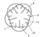
Among the figure: 1, the first heat radiation chamber; 2, the second heat radiation chamber; 3, passage; 4, led circuit plate; 5, LED illuminator; 6, lampshade; 7, lamp holder; 8, power supply circuit board; 9, power supply chamber; 10, cover plate; 11, chamber wall; 12, radiator structure; 13, through hole.
The specific embodiment
Below, introduce the specific embodiment of the utility model in conjunction with accompanying drawing.
Like Fig. 1-shown in Figure 3; A kind of LED lamp of split heat radiation; The first heat radiation chamber 1 and the flat second box-like heat radiation chamber 2 that comprise tubular; One end of the said first heat radiation chamber 1 is connected with the said second heat radiation chamber 2 and communicates; The said second heat radiation chamber 2 is shaped at least one passage 3, and the other end of the said first heat radiation chamber 1 has opening, thereby forms the hollow cooling system of the said first heat radiation chamber 1 and dispel the heat chamber 1 again through the path of the said second heat radiation chamber 2 until the circulation of air of flowing out from said passage 3 from said opening through said first; The wall along the chamber of its length direction 11 of the said first heat radiation chamber 1 is integrated with radiator structure 12, holds around said chamber wall 11 configuration led circuit plates 4, on said led circuit plate 4, sets LED illuminator 5, and sets lampshade 6; The said second heat radiation chamber 2 also is connected with the power supply chamber 9 that power supply is installed and communicates, and said power supply chamber 9 also is connected with lamp holder 7, and said power supply comprises a power supply circuit board 8.
The other end cover cap plate lid 10 of the said first heat radiation chamber 1, and on plate lid 10, open system through hole 13 and supply air to flow into the said second heat radiation chamber 2.
Said power supply connects with led circuit plate 4 and supplies power to led circuit plate 4.
Perhaps; A kind of LED lamp of split heat radiation; The first heat radiation chamber 1 and the flat second box-like heat radiation chamber 2 that comprise tubular; One end of the said first heat radiation chamber 1 is connected with Room 2, the said second heat radiation chamber and communicates; Room 2, the said second heat radiation chamber are shaped at least one passage 3, and the other end of the said first heat radiation chamber 1 has opening, thereby form the hollow cooling system of the said first heat radiation chamber and dispel the heat chamber 1 again through the path of the said second heat radiation chamber 2 until the circulation of air of flowing out from said passage 3 from said opening through said first; The wall along the chamber of its length direction 11 of the said first heat radiation chamber 1 is integrated with radiator structure 12, holds around said chamber wall 11 configuration led circuit plates 4, on said led circuit plate 4, sets LED illuminator 5, and sets lampshade 6; In the said second heat radiation chamber 2 power supply is installed, and the said second heat radiation chamber, 2 connection lamp holders 7, said power supply comprises a power supply circuit board 8.
The other end cover cap plate lid of the said first heat radiation chamber, and cover out the system through hole at plate and supply air to flow into the said second heat radiation chamber.
Said power supply connects with the led circuit plate and supplies power to the led circuit plate.
Like Fig. 4-Figure 11, first heat radiation chamber 1 and vertical plane of structure its length direction be shaped as circle, ellipse or polygon.
Like Fig. 3-shown in Figure 7, radiator structure 12 is a fin; Perhaps like Fig. 8-shown in Figure 11, radiator structure 12 promptly is a chamber wall 11, is plate body.The material of radiator structure 12 and chamber wall 11 is metal materials such as copper, aluminium, alloy, or processes for nonmetallic materials.
Led circuit plate 4 is the circuit board that metal or general substrate are processed.
Like Fig. 4-shown in Figure 11, the shape of said lampshade 6 and vertical plane of structure its length direction and cover plate 11 be circular, oval, polygon or multi sphere shape limit.But the material glass of the material of lampshade 6 and cover plate 11, plastics or PC material are processed.
The radiator structure of the utility model can be applied to multiple LED light fixture, for example: LED bulb, courtyard lamp, street lamp, T5, T8, T10 fluorescent tube.
The lampshade 6 and the first heat radiation chamber 1 are formed in one, or independent individuality mutually riveted joint or screens or be spirally connected form, can reach at a distance from high temperature, waterproof and dustproof and insulation purpose.
Describe the specific embodiment of the utility model above in detail.The embodiment that should be appreciated that the utility model is not limited in this, and its purpose only is used to help to understand the spirit of the utility model.Under the guidance of the spirit that the utility model disclosed, the various variant that the utility model is done all fall in the scope of the utility model.
Claims (6)
1. the LED lamp of split heat radiation; It is characterized in that: the first heat radiation chamber and the flat second box-like heat radiation chamber that comprise tubular; One end of the said first heat radiation chamber is connected with the said second heat radiation chamber and communicates; The said second heat radiation chamber is shaped at least one passage; The other end of the said first heat radiation chamber has opening, thereby forms the hollow cooling system of the said first heat radiation chamber and dispel the heat chamber again through the path of the said second heat radiation chamber until the circulation of air of flowing out from said passage from said opening through said first; Being integrated along the chamber of its length direction wall and radiator structure of the said first heat radiation chamber holds around said chamber wall configuration led circuit plate, on said led circuit plate, sets the LED illuminator, and sets lampshade; The said second heat radiation chamber also is connected with the power supply chamber that power supply is installed and communicates, and said power supply chamber also is connected with lamp holder, and said power supply comprises a power supply circuit board.
2. the LED lamp of a kind of split heat radiation according to claim 1 is characterized in that: the other end cover cap plate lid of the said first heat radiation chamber, and cover out the system through hole at plate and supply air to flow into the said second heat radiation chamber.
3. the LED lamp of a kind of split heat radiation according to claim 1 is characterized in that: said power supply connects with the led circuit plate and supplies power to the led circuit plate.
4. the LED lamp of split heat radiation; It is characterized in that: the first heat radiation chamber and the flat second box-like heat radiation chamber that comprise tubular; One end of the said first heat radiation chamber is connected with the said second heat radiation chamber and communicates; The said second heat radiation chamber is shaped at least one passage; The other end of the said first heat radiation chamber has opening, thereby forms the hollow cooling system of the said first heat radiation chamber and dispel the heat chamber again through the path of the said second heat radiation chamber until the circulation of air of flowing out from said passage from said opening through said first; Being integrated along the chamber of its length direction wall and radiator structure of the said first heat radiation chamber holds around said chamber wall configuration led circuit plate, on said led circuit plate, sets the LED illuminator, and sets lampshade; In the said second heat radiation chamber power supply is installed, and the said second heat radiation chamber connection lamp holder, said power supply comprises a power supply circuit board.
5. the LED lamp of a kind of split heat radiation according to claim 4 is characterized in that: the other end cover cap plate lid of the said first heat radiation chamber, and cover out the system through hole at plate and supply air to flow into the said second heat radiation chamber.
6. the LED lamp of a kind of split heat radiation according to claim 4 is characterized in that: said power supply connects with the led circuit plate and supplies power to the led circuit plate.
Priority Applications (1)
| Application Number | Priority Date | Filing Date | Title |
|---|---|---|---|
| CN2011203166087U CN202216016U (en) | 2011-08-29 | 2011-08-29 | Separating type heat radiation LED lamp |
Applications Claiming Priority (1)
| Application Number | Priority Date | Filing Date | Title |
|---|---|---|---|
| CN2011203166087U CN202216016U (en) | 2011-08-29 | 2011-08-29 | Separating type heat radiation LED lamp |
Publications (1)
| Publication Number | Publication Date |
|---|---|
| CN202216016U true CN202216016U (en) | 2012-05-09 |
Family
ID=46015269
Family Applications (1)
| Application Number | Title | Priority Date | Filing Date |
|---|---|---|---|
| CN2011203166087U Expired - Lifetime CN202216016U (en) | 2011-08-29 | 2011-08-29 | Separating type heat radiation LED lamp |
Country Status (1)
| Country | Link |
|---|---|
| CN (1) | CN202216016U (en) |
Cited By (3)
| Publication number | Priority date | Publication date | Assignee | Title |
|---|---|---|---|---|
| CN102261595A (en) * | 2011-08-29 | 2011-11-30 | 沈李豪 | A separate heat dissipation LED lamp |
| CN102798013A (en) * | 2012-08-06 | 2012-11-28 | 深圳市中电照明股份有限公司 | Convection radiating type LED (light-emitting diode) bulb |
| CN103672806A (en) * | 2012-09-26 | 2014-03-26 | 海洋王(东莞)照明科技有限公司 | LED radiator |
-
2011
- 2011-08-29 CN CN2011203166087U patent/CN202216016U/en not_active Expired - Lifetime
Cited By (5)
| Publication number | Priority date | Publication date | Assignee | Title |
|---|---|---|---|---|
| CN102261595A (en) * | 2011-08-29 | 2011-11-30 | 沈李豪 | A separate heat dissipation LED lamp |
| CN102261595B (en) * | 2011-08-29 | 2013-11-06 | 沈李豪 | Split type heat dissipation LED lamp |
| CN102798013A (en) * | 2012-08-06 | 2012-11-28 | 深圳市中电照明股份有限公司 | Convection radiating type LED (light-emitting diode) bulb |
| CN102798013B (en) * | 2012-08-06 | 2014-09-17 | 深圳市中电照明股份有限公司 | Convection radiating type LED (light-emitting diode) bulb |
| CN103672806A (en) * | 2012-09-26 | 2014-03-26 | 海洋王(东莞)照明科技有限公司 | LED radiator |
Similar Documents
| Publication | Publication Date | Title |
|---|---|---|
| JP2013527575A (en) | Heat dissipation device for LED bulb and LED bulb with high heat dissipation | |
| JP2011103275A (en) | Light emitting diode lighting fixture | |
| CN204785745U (en) | Ball bubble lamp | |
| CN102155663A (en) | A kit-type heat dissipation structure for LED or SMD LED light bulbs and lamps | |
| KR100984958B1 (en) | Retrofit led lamp, method for making the same, and retrofit multi led lamp set | |
| CN102650389B (en) | LED (Light-Emitting Diode) lamp with heat radiation structure | |
| CN202017973U (en) | Projector light | |
| CN102305362B (en) | Light-emitting diode (LED) tube lamp | |
| CN202203905U (en) | LED (light emitting diode) cylinder lamp and lamp body thereof | |
| CN102261595B (en) | Split type heat dissipation LED lamp | |
| CN205261318U (en) | Open -installation tube lamp | |
| CN203907552U (en) | Lamp heat sink and LED mining lamp | |
| CN204062565U (en) | Integrated LED lamp | |
| CN201521931U (en) | LED down lamp | |
| CN204254313U (en) | The LED self-ballasted lamp of diffusion shell and convection heat dissipation structure after band | |
| CN202884581U (en) | High-power light-emitting diode (LED) fluorescent tube structure capable of lighting in 360 degrees | |
| CN202501269U (en) | LED down lamp | |
| CN201672343U (en) | light emitting device | |
| CN202215993U (en) | LED (Light-Emitting Diode) lamp apparatus capable of increasing multidirectional light-emitting efficiency | |
| CN203615152U (en) | Omnidirectional LED (light emitting diode) lamp | |
| CN203757426U (en) | Multi-lighting effect LED tube light | |
| CN202220988U (en) | Energy-saving LED lamp | |
| CN202469984U (en) | Heat dissipation structure of LED parabolic downlight | |
| CN201836773U (en) | Improved structure of LED recessed lights | |
| CN209229377U (en) | LED spotlight group with cone cell radiator |
Legal Events
| Date | Code | Title | Description |
|---|---|---|---|
| C14 | Grant of patent or utility model | ||
| GR01 | Patent grant | ||
| AV01 | Patent right actively abandoned |
Granted publication date: 20120509 Effective date of abandoning: 20131106 |
|
| RGAV | Abandon patent right to avoid regrant |