CN202210670U - Cable branch cabinet - Google Patents
Cable branch cabinet Download PDFInfo
- Publication number
- CN202210670U CN202210670U CN2011202751702U CN201120275170U CN202210670U CN 202210670 U CN202210670 U CN 202210670U CN 2011202751702 U CN2011202751702 U CN 2011202751702U CN 201120275170 U CN201120275170 U CN 201120275170U CN 202210670 U CN202210670 U CN 202210670U
- Authority
- CN
- China
- Prior art keywords
- casing
- cabinet body
- cable branch
- side cover
- cabinet
- Prior art date
- Legal status (The legal status is an assumption and is not a legal conclusion. Google has not performed a legal analysis and makes no representation as to the accuracy of the status listed.)
- Expired - Fee Related
Links
- 230000002146 bilateral effect Effects 0.000 claims description 4
- 238000010276 construction Methods 0.000 abstract description 5
- 238000012423 maintenance Methods 0.000 abstract 1
- VYPSYNLAJGMNEJ-UHFFFAOYSA-N Silicium dioxide Chemical compound O=[Si]=O VYPSYNLAJGMNEJ-UHFFFAOYSA-N 0.000 description 2
- 238000009434 installation Methods 0.000 description 2
- 230000009286 beneficial effect Effects 0.000 description 1
- 239000002131 composite material Substances 0.000 description 1
- 230000007797 corrosion Effects 0.000 description 1
- 238000005260 corrosion Methods 0.000 description 1
- 230000007812 deficiency Effects 0.000 description 1
- 230000002950 deficient Effects 0.000 description 1
- 238000005516 engineering process Methods 0.000 description 1
- 238000007710 freezing Methods 0.000 description 1
- 238000009413 insulation Methods 0.000 description 1
- 238000000034 method Methods 0.000 description 1
- 239000000377 silicon dioxide Substances 0.000 description 1
- 239000002689 soil Substances 0.000 description 1
- XLYOFNOQVPJJNP-UHFFFAOYSA-N water Substances O XLYOFNOQVPJJNP-UHFFFAOYSA-N 0.000 description 1
Images

Landscapes
- Laying Of Electric Cables Or Lines Outside (AREA)
Abstract
The utility model discloses a cable branch cabinet which comprises a cabinet body, wherein side covers are respectively arranged on the left side and the right side of the cabinet body, one end of each of the side covers is articulated with the top of the cabinet body; the inside walls of the side covers are articulated with one end of a movable supporting rod, and the other end of the movable supporting rod is articulated on the inside wall of the cabinet body. A voltage sensor is arranged on a two-way sleeve in the cabinet body, and a voltage display screen is arranged on the side wall of the cabinet body. With the adoption of the structure, the left side cover and the right side cover can be turned up at the same time, and can be fixed by the supporting rod, and the wiring can be conducted on the left side and right side at the same time without interference with each other, so that the construction efficiency can be improved; due to the voltage display device arranged on the cabinet body, a worker can timely know the voltage condition in the cabinet; and the cable branch cabinet also has the characteristics that the cable branch cabinet is compact in structure, small in volume, simple and convenient to install and free from maintenance.
Description
Technical field
The utility model relates to a kind of cable branch box, especially is applicable to the cable branch box of underground cable system.
Background technology
The following defective of existing cable branch box ubiquity, the first, because the case lid design is reasonable inadequately, when carrying out the wiring construction in a side, case lid need be passed to opposite side, so can only not only increased work difficulty, and work efficiency be the end of than in side construction.In addition, do not have the Presentation Function of voltage cable on the traditional cable feeder pillar,, bring some inconvenience for personnel's fitting operation so do not understand the voltage condition in the case.
Summary of the invention
In order to overcome above-mentioned deficiency, the utility model purpose is to provide a kind of and can operates simultaneously and easy to operate cable branch box in the both sides of casing.
To achieve these goals, the technical scheme of the utility model employing is:
Cable branch box includes casing, and the left and right sides of said casing is respectively equipped with side cover, and an end of said side cover and the top of casing are hinged; The inwall of institute's art side cover and an end of movable support rod are hinged, and the other end of movable support rod is hinged on the inwall of casing.
Bilateral sleeve pipe in the said casing is provided with voltage sensor, and the sidewall of casing is provided with the voltage display screen.
The base of said side cover is provided with handle, and an end of said handle and the base of side cover are hinged, and the other end offers notch, on casing, is provided with and the corresponding bolt of notch.
The beneficial effect of the utility model: owing to adopt above-mentioned structure, left and right side cap can upwards be dug simultaneously, and implements fixingly through support bar, and the left and right sides can be implemented the wiring operation simultaneously, does not hinder between mutually, thereby can improve the efficient of construction; Owing on casing, established the voltage display unit, made the staff can in time understand the voltage condition in the case; The utility model has also that compact conformation, volume are little, simple installation and non-maintaining characteristics.
Description of drawings
Below in conjunction with accompanying drawing the utility model is done further to specify.
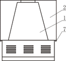
Fig. 1 is the structural representation of the utility model;
Fig. 2 is the structural representation after side cover shown in Figure 1 is opened.
Among the figure: 1, casing; 2, side cover; 3, movable support rod; 4, bilateral sleeve pipe; 5, voltage sensor; 6, voltage display screen; 7, handle; 8, bolt.
Embodiment
Like Fig. 1, shown in 2, cable branch box includes casing 1, and the left and right sides of said casing 1 is respectively equipped with side cover 2, and an end of said side cover 2 and the top of casing 1 are hinged; The inwall of institute's art side cover 2 and an end of movable support rod 3 are hinged, and the other end of movable support rod 3 is hinged on the inwall of casing 1.
Bilateral sleeve pipe 4 in the casing 1 is provided with voltage sensor 5, and the sidewall of casing 1 is provided with voltage display screen 6.The base of said side cover 2 is provided with handle 7, and an end of said handle 7 and the base of side cover 2 are hinged, and the other end offers notch, on casing, is provided with and the corresponding bolt 8 of notch.
The utility model also has following characteristics: the oblique opening structure that adopts all insulation, totally-enclosed, all-weather and full protection; Flood fighting water logging bubble, dirty, the anti-freezing dew, corrosion-resistant of anti-soil; Cable plug adopts European rendezvous method, easy construction; Composite silica rubber cable plug in the casing has semiconductive shielding layer, can guarantee the personal safety of installation personnel.
The above is the preferred implementation of the utility model, can not limit the interest field of the utility model certainly with this.Should be pointed out that for those skilled in the art, the technical scheme of the utility model is made amendment or is equal to replacement, do not break away from the protection range of the utility model.
Claims (3)
1. a cable branch box includes casing, it is characterized in that: the left and right sides of said casing is respectively equipped with side cover, and an end of said side cover and the top of casing are hinged; The inwall of institute's art side cover and an end of movable support rod are hinged, and the other end of movable support rod is hinged on the inwall of casing.
2. cable branch box according to claim 1 is characterized in that: the bilateral sleeve pipe in the said casing is provided with voltage sensor, and the sidewall of casing is provided with the voltage display screen.
3. cable branch box according to claim 1 is characterized in that: the base of said side cover is provided with handle, and an end of said handle and the base of side cover are hinged, and the other end offers notch, on casing, is provided with and the corresponding bolt of notch.
Priority Applications (1)
| Application Number | Priority Date | Filing Date | Title |
|---|---|---|---|
| CN2011202751702U CN202210670U (en) | 2011-08-01 | 2011-08-01 | Cable branch cabinet |
Applications Claiming Priority (1)
| Application Number | Priority Date | Filing Date | Title |
|---|---|---|---|
| CN2011202751702U CN202210670U (en) | 2011-08-01 | 2011-08-01 | Cable branch cabinet |
Publications (1)
| Publication Number | Publication Date |
|---|---|
| CN202210670U true CN202210670U (en) | 2012-05-02 |
Family
ID=45990213
Family Applications (1)
| Application Number | Title | Priority Date | Filing Date |
|---|---|---|---|
| CN2011202751702U Expired - Fee Related CN202210670U (en) | 2011-08-01 | 2011-08-01 | Cable branch cabinet |
Country Status (1)
| Country | Link |
|---|---|
| CN (1) | CN202210670U (en) |
Cited By (2)
| Publication number | Priority date | Publication date | Assignee | Title |
|---|---|---|---|---|
| CN103368126A (en) * | 2013-06-19 | 2013-10-23 | 国家电网公司 | 10kV outdoor high-voltage cable distribution box and installation method thereof |
| CN104466877A (en) * | 2013-09-18 | 2015-03-25 | 上海翔洲电气科技有限公司 | Safe and rapid connection box with voltage display |
-
2011
- 2011-08-01 CN CN2011202751702U patent/CN202210670U/en not_active Expired - Fee Related
Cited By (4)
| Publication number | Priority date | Publication date | Assignee | Title |
|---|---|---|---|---|
| CN103368126A (en) * | 2013-06-19 | 2013-10-23 | 国家电网公司 | 10kV outdoor high-voltage cable distribution box and installation method thereof |
| CN103368126B (en) * | 2013-06-19 | 2016-12-28 | 国家电网公司 | 10kV outdoor high voltage cable branch box and installation method thereof |
| CN104466877A (en) * | 2013-09-18 | 2015-03-25 | 上海翔洲电气科技有限公司 | Safe and rapid connection box with voltage display |
| CN104466877B (en) * | 2013-09-18 | 2017-12-26 | 上海翔洲电气科技有限公司 | A kind of safe and efficient connecting box of display with voltage |
Similar Documents
| Publication | Publication Date | Title |
|---|---|---|
| CN202353170U (en) | Cable junction box | |
| CN207198214U (en) | A kind of three-phase intelligent electric-energy meter | |
| CN201616626U (en) | Junction box for electrical appliance | |
| CN202978034U (en) | Improved power distribution box with alarm device | |
| CN203422402U (en) | Waterproof electricity meter box | |
| CN203732594U (en) | Comprehensive temporary electricity consumption box | |
| CN204313863U (en) | Multi-functional water conservancy automatic monitoring surveys cabinet | |
| CN202978038U (en) | Safe outdoor power equipment box body | |
| CN204776536U (en) | Guard shield type cold insulated cabinet | |
| CN207705744U (en) | A kind of buried cable branch box | |
| CN201946896U (en) | Hinge mounting holes of combined transformer box and door | |
| CN206961618U (en) | A kind of oil-filled transformer Buchholz relay protective cover | |
| CN206490314U (en) | A kind of switch cubicle and its cabinet | |
| CN204739379U (en) | Terminal advertising screen supporting seat | |
| CN222419135U (en) | An environmental protection monitoring device that is easy to install | |
| CN202032432U (en) | Anti-explosion high-pole lamp device | |
| CN202279389U (en) | Cable pipe box | |
| CN201967262U (en) | Concealed installation modular terminal combination electric appliance box | |
| CN202042714U (en) | Freestyle telescopic socket | |
| CN201924705U (en) | Transformer box door lock limiting device of outdoor box | |
| CN216355351U (en) | Distribution switch control cabinet suitable for charging system | |
| CN203022379U (en) | Enclosure system for field production line equipment | |
| CN203541566U (en) | Button station rotating mechanism | |
| CN203301088U (en) | European cable branch box | |
| CN203942150U (en) | GIS combined electrical apparatus three utmost point separate-box type sleeve pipes |
Legal Events
| Date | Code | Title | Description |
|---|---|---|---|
| C14 | Grant of patent or utility model | ||
| GR01 | Patent grant | ||
| C17 | Cessation of patent right | ||
| CF01 | Termination of patent right due to non-payment of annual fee |
Granted publication date: 20120502 Termination date: 20120801 |